Aviation Design super scorpion User manual
AVIATION DESIGN - ZI le Chenet - 91490 MILLY LA FORET – FRANCE - Tel : int+ 33 1 64 98 93 93 - [email protected] –
www.adjets.com
1
SUPER SCORPION
Assembly
Manual
AVIATION Design
ZI le chenet, 91490 Milly La Foret, FRANCE
Tel : 33 1 64 98 93 93
Fax : 33 1 64 98 93 88
www.adjets.com
Version 01/03/2007

AVIATION DESIGN - ZI le Chenet - 91490 MILLY LA FORET – FRANCE - Tel : int+ 33 1 64 98 93 93 - [email protected] –
www.adjets.com
2
INTRODUCTION
ScoRpion is our new jet trainer. It is fully composite, delivered assembled and painted.
It is designed for jet beginner with following objective :
-Very easy to fly.
-Short take off and landing due to big airfoil thickness (13%), large flaps and low wing loading
-Very fast assembly
-Easy access to engine (big engine hatch)
-Easy access to fuel tank , ECU and radio with a large fuselage hatch
-Easy radio installation with big fuselage hatch and servo cover supplied
The ScoRpion is fully molded in composite material.
The model comes to you finished, fully molded in composite material and painted in mold. All
bulkeads are glued. All control surfaces are hinged. No gluing are required. This model has plug in
wings, stabs and fin booms for an easier transport.
All necessary hardware are included in the parcel
Assembly require only few hours to fit engine and radio.
ScoRpion ARF model includes :
- High quality epoxy-glass fuselage painted.
- All plywood and wood parts premounted.
- Fully molded wings with winglets, stabs and fins painted
- High tensile aluminum wing joining tube.
- Access hatch and canopy requiring no additional framework.
- All hardware (screws, servo cover, ...)
- Instructions in English with pics.
Parts required to complete the kit :
-Clear canopy
-Cockpit detail kit
-4 liters kevlar fuel cell
-or 4 liters tank + UBT
-Deluxe retractable landing gear
with special CNC oleo legs and
wheels set on bearing + brakes
-Or Deluxe gear + 2 electovalves
for gear and brakes
-Air brake or air brake with electrovalve
-Stainless steel tailpipe

AVIATION DESIGN - ZI le Chenet - 91490 MILLY LA FORET – FRANCE - Tel : int+ 33 1 64 98 93 93 - [email protected] –
www.adjets.com
3
DISCLAIMER
AVIATION Design assumes no liability for the operation and use of these products.
The owner and operator of these products should have the necessary experience and exercise common
sense. Said owner and operator must have a valid Model Airplane licence and insurance as required.
Assembly Instructions
Installation of the radio equipment
Components need:
Elevator: 4 servos 8 kg torque
Rudder: 2 servos 6 kg torque
Ailerons: 2 servos 8 kg torque
Flaps: 2 servos 8 kg torque
Steering nose wheels: 1 servo 5 kg torque
Receiver and switch
We also recommand the use of a Power box system or similar system required for the big number of
high torque servos

AVIATION DESIGN - ZI le Chenet - 91490 MILLY LA FORET – FRANCE - Tel : int+ 33 1 64 98 93 93 - [email protected] –
www.adjets.com
4
Joining front fuselage to rear fuselage
Insert 6 x 3 mm blind nut in the rear section
Screw the front fuselage to the rear fuselage with six
3 mm x 20 mm allen screws
To disassemble the front fuselage you will have to
remove the fuel tank

AVIATION DESIGN - ZI le Chenet - 91490 MILLY LA FORET – FRANCE - Tel : int+ 33 1 64 98 93 93 - [email protected] –
www.adjets.com
5
Gear :
Please, use only the oleo legs supply by Aviation Design.
If you use standard oleo, you will have to modify the gear position and gear door position
Draw the fuselage axis under the fuselage with a ruler
Draw the front gear door location and main gear door
location according to the drawing and template
Cut all gear doors using a fine diamond disc and dremel tool
380 mm
15 Inhes
715 m
m
25 mm
115 m
m

AVIATION DESIGN - ZI le Chenet - 91490 MILLY LA FORET – FRANCE - Tel : int+ 33 1 64 98 93 93 - [email protected] –
www.adjets.com
6
Fit the main gear on the plywood mount a drill four 6 mm hole in the fuselage in front of the screw
location
Screw each gear with four 3x20 mm parker screws
Fit the front gear on the plywood mount
Drill 4 x 2 mm hole
Screw the front gear with four 3x20 mm parker screws
Screw the steering servo inverted on the plywood frame
Make a hole in the plywood frame for the steering steel
wire.
Connect servo to steering arm with 2 mm link + steel
wire .
Check that the nose gear retract and extand without
problem witht he steering wire.

AVIATION DESIGN - ZI le Chenet - 91490 MILLY LA FORET – FRANCE - Tel : int+ 33 1 64 98 93 93 - [email protected] –
www.adjets.com
7
Connect all gear tubing as described in the gear manual
Fit the brake tubings and attach them with T rap
The air bottle can be fitted under the plywood plate in the nose. You can hold it wth T rap

AVIATION DESIGN - ZI le Chenet - 91490 MILLY LA FORET – FRANCE - Tel : int+ 33 1 64 98 93 93 - [email protected] –
www.adjets.com
8
If necessary, add 2 soft springs or rubber bands to extand the wire when the front gear retract

AVIATION DESIGN - ZI le Chenet - 91490 MILLY LA FORET – FRANCE - Tel : int+ 33 1 64 98 93 93 - [email protected] –
www.adjets.com
9
Stabs
Servos installation
Important : the servo MUST be a high quality servo, 8 kg torque, with metallic gears.
( It is also possible to use one single 8 kg torque servo for each stab )
Screw the 2 servos on the plywood mount
Connect the 2 servo arms with M3 link. We also recommand the use of aluminium servo a.rm
Test the 2 servos working together
The servo lead must be fixed to the fuselage and protected from engine.
Ball link and control horn
Fit the ball link of theM4 threated rod
Screw the ball link on the control horn with M3 screw and secure with blind nut

AVIATION DESIGN - ZI le Chenet - 91490 MILLY LA FORET – FRANCE - Tel : int+ 33 1 64 98 93 93 - [email protected] –
www.adjets.com
10
Stabs installation
Important : the 2 stabs MUST be balanced
The stab are normally pre balanced at the factory. But we recommand to check if it is correctly done
When the stab is fitted in the tubing, it must be free in rotation : not hard point, no unbalance.
If necessary, you will have to drill a hole in the stab root and glue some lest in the leading edge to
balance them.
Slide the plastic washer on the aluminium tube if necessary
so the stab don’t touch the fuselage
Slide the stab in the tube.
Check again the clearance of the stab and the fuselage. The
stab must not touch the fuselage when it rotate.
Slide the aluminium control arm on the tube. Insert a plastic
washer between wood and control horn.
Put the stab horizontal. Put the control arm vertical.
Screw and secure the 2 screws
Drill a 2.5 mm hole through the arm and through the aluminium
tube to secure it. Tapping it with M3 screw-tap.

AVIATION DESIGN - ZI le Chenet - 91490 MILLY LA FORET – FRANCE - Tel : int+ 33 1 64 98 93 93 - [email protected] –
www.adjets.com
11
Connect the servo to the arm with the large M4 ball link and M4 threaded rod.
Glue them with threadlock.

AVIATION DESIGN - ZI le Chenet - 91490 MILLY LA FORET – FRANCE - Tel : int+ 33 1 64 98 93 93 - [email protected] –
www.adjets.com
12
Aileron and flaps servos :
If necessary increase the hole for the servo location in the wings with a permagrit rotating tool for the
aileron and flaps
Screw the servo in the servo cover (we recommand to glue it with silicon glue for more security)
Put in position the servo cover on the wings
Drill 4 x 1 mm hole in the wings for the screws
Cut a slot in the control surface for the fiber control horn
Glue with fast epoxy the control horn
Connect two 2 mm link with M2 threaded rod
Screw the servo cover with the 4 parker screws
Connect the servo with the control horn
Apply thread lock.
F
la
p
s control horn
A
ileron control horn

AVIATION DESIGN - ZI le Chenet - 91490 MILLY LA FORET – FRANCE - Tel : int+ 33 1 64 98 93 93 - [email protected] –
www.adjets.com
13
Make a 15 mm hole in the wing root for the
servo electric wire
Don’t make the hole too big so that the conector
can’t fall in the wing
Sold electric wire for the flaps and aileron
Make a 5 mm corresponding hole in the fuselage
for the electric wire
Don’t make the hole too big so that the conector
can’t fall in the fuselage
Wing pins
Sand half of the wing pins to glue them in the wings
Glue them in the wing with epoxy

AVIATION DESIGN - ZI le Chenet - 91490 MILLY LA FORET – FRANCE - Tel : int+ 33 1 64 98 93 93 - [email protected] –
www.adjets.com
14
Secure the wings :
Fit the wing joiner tube through the fuselage.
Take care to put it at the center (same lenght left and right
(about 300 mm).
Install the left and right wings.
Make a 2.5 mm hole at 250 mm from the wing root throught the
wing and aluminium tube to secure the wings (on the bottom of
the wing, a plywood reinforcement is fitted)
Threated the wing tube and wing at M3 mm and secure wings
with a M3x25 screw
You can also secure the tube in the fuselage, so the tube will not
move during assembling and desassembling.
Make a 2.5 mm hole in the center of the fuselage from the
engine hatch. Drill the hole throught the fiber tube and
aluminium tube to secure the tube.
Screw a 3 x 16 mm parker screw through the fiber tube and
aluminium tube, so the tube will not move during assembling and desassembling.

AVIATION DESIGN - ZI le Chenet - 91490 MILLY LA FORET – FRANCE - Tel : int+ 33 1 64 98 93 93 - [email protected] –
www.adjets.com
15
Rudder servos :
Process as the wing servo :
Increase the hole for the servo location in the booms with a permagrit rotating tool for the rudder
Screw the servo in the servo cover (we recommand to glue it with silicon glue for more security)
Put in place the servo cover on the fin
Drill 4 x 1 mm hole in the wings for the screws
Cut a slot in the control surface for the fiber control
horn
Glue with fast epoxy the control horn
Connect two 3 mm link with M3 threaded rod
Screw the servo cover with the 4 parker screws
Connect the servo with the control horn
Apply thread lock.
Make a 20 mm hole in the fin root for the servo electric
wire.

AVIATION DESIGN - ZI le Chenet - 91490 MILLY LA FORET – FRANCE - Tel : int+ 33 1 64 98 93 93 - [email protected] –
www.adjets.com
16
Make a 5 mm corresponding hole in
the fuselage for the electric wire.
Don’t make the hole too big so that
the conector can’t fall in the
fuselage.
Sold electric wire for the 2 rudder in
Y
Secure the fins :
Fit the fins on the fuselage.
Make a 2.5 mm hole at 15 mm from
the fin root throught the fuselage and
aluminium tube to secure the fins
Threated the tube and fuselage at M3
mm and secure fin with a M3x15
screw

AVIATION DESIGN - ZI le Chenet - 91490 MILLY LA FORET – FRANCE - Tel : int+ 33 1 64 98 93 93 - [email protected] –
www.adjets.com
17
Fuel tank
Connect the fuel tank to the clunk as the photo.
Check that there is no leak before to fit it in fuselage.
Drill a 3 mm hole in the bottom of the fuselage for the
fuel vent
The fuel tank is connected to the small catch tank (200
cc) or UAT catch tank to be sure that there is no bubble in
the fuel line.
The tubing from the main tank to the catch tank and to the
catch tank to the fuel pump must be gasoline tubing (no
silicone tubing). Also for the air vent tube.
The catch tank is glue with double face tape or with
rubber band on the top of the main tank.
Hold the fuel tank with rubber bands or silicon glue
Filling the fuel tanks :
Connect your pump and fill
the system in direction of the
tank. It will first fill the catch
tank and after the main tank.
The main tank will be full
when fuel come from the air
vent tube.
When tanks are ful, close the
filling tubing.
Do not close the air vent tube after.
The system is ready for starting.
Fuel vent

AVIATION DESIGN - ZI le Chenet - 91490 MILLY LA FORET – FRANCE - Tel : int+ 33 1 64 98 93 93 - [email protected] –
www.adjets.com
18
STEEL TAILPIPE EXHAUST
Fit in the fuselage the tailpipe from the fuselage
hatch.
Tailpipe will be screw on the rear engine frame with
3 x 3 mm diameter parker screw at 120°
Fiber Exhaust cone :
Glue with CA a 6 mm wood pins on 2 opposite sides of the exhaust
cone
Drill the 2 corresponding 6 mm
hole in the rear fuselage
Screw the tailpipe with 2
x 2mm parker screws to
secure the wood pins

AVIATION DESIGN - ZI le Chenet - 91490 MILLY LA FORET – FRANCE - Tel : int+ 33 1 64 98 93 93 - [email protected] –
www.adjets.com
19
Engine installation :
If necessary, cut a hole in the inlets for the electric starter location
Adjust the position of the engine / beginning of the exhaust tube
The engine must be screw with 4 times 3x20 mm parker screw to the rear position.
Secure all electric wire and fuel tubing in front of the engine in the fuselage

AVIATION DESIGN - ZI le Chenet - 91490 MILLY LA FORET – FRANCE - Tel : int+ 33 1 64 98 93 93 - [email protected] –
www.adjets.com
20
ECU installation :
Fit the ECU in one side of the plane.
Fit the fuel pump and valves just rear to the ECU and hold them with T rap.
Gear valves, air tank, batterie, antenae
Other manuals for super scorpion
3
Table of contents
Other Aviation Design Toy manuals

Aviation Design
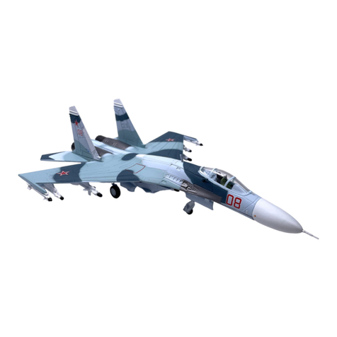
Aviation Design SUKHOI SU-27 User manual

Aviation Design
Aviation Design Falcon 7X User manual

Aviation Design
Aviation Design super scorpion User manual

Aviation Design
Aviation Design Rafale C User manual

Aviation Design
Aviation Design super scorpion User manual

Aviation Design
Aviation Design super scorpion User manual

Aviation Design
Aviation Design Phoenix User manual
Aviation Design
Aviation Design STORM User manual

Aviation Design
Aviation Design F-16 User manual
Aviation Design
Aviation Design SPITFIRE MK IX User manual