AVID HIFI VOLVERE User manual

VOLVERE
USER MANUAL

2

3
Table of Contents
Extended 5-Year Warranty
AVID is pleased to extend the normal warranty duration to 5-Years from the date of
original factory shipping. This warranty is transferable in the unlikely event that you
would sell this unit onto another party. Register your product at;
www.avidhifi.com/register
WARNING
YOU MUST ALWAYS REMOVE THE PLATTER AND BEARING
AND USE THE TRANSIT PACKAGING WHEN YOU TRANSPORT
YOUR TURNTABLE OR YOU MAY DAMAGE THE BEARING
“DON’T PUT IT ON THE BACK SEAT OF YOUR CAR—YOU’LL BREAK IT“
Section Page
Preface 4
Introduction 4
Warning 4
Packaging 4
Parts Checklist 4
Set-up Instructions 5
Power Supply 9
Servicing 10
Cleaning 10
Specifications 10
Warranty-Terms and Conditions 11

4
Preface
Please take time to read this Instruction Manual before unpacking your Volvere Turntable.
This product is meticulously engineered and whilst damage is unlikely with careful handling, the sheer mass of some of
the parts could damage the less robust parts within its design. Please keep in mind that certain parts have been
deliberately excluded from the warranty, so it is essential to handle and operate the turntable with care and attention.
Introduction
The Volvere is an audio turntable manufactured to extreme limits of precision, design and detail. There are many unique
and novel features in this product and its design allows you to install the pick-up arm and cartridge of your choice.
With correct ancillary equipment it will take your listening pleasure to new levels of excellence.
Whilst it shares some features found in other turntables, it has been designed without compromise not trying to emulate
or improve existing designs but redefine the whole thinking behind turntable design.
We hope that you enjoy this product for many years!
Warnings
1. To prevent fire or electric shocks do not expose either the power supply or motor to rain or moisture
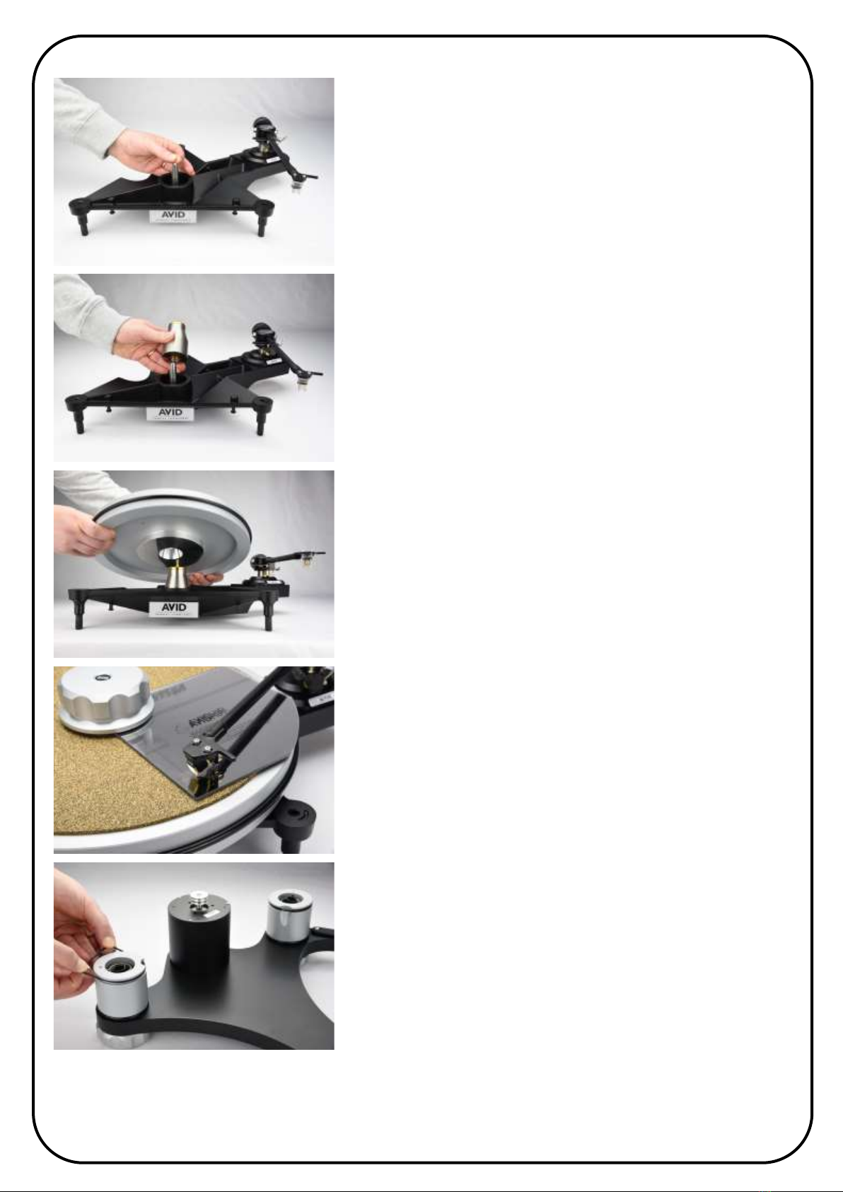
2. The Main Bearing contains a Sapphire Cup Jewel and can be damaged if proper care is not taken, such as moving
the turntable or dropping the platter when fitting and this part is excluded from warranty
3. The threaded spindle is made from brass for sonic reasons and is a much softer than the stainless steel clamp.
If cross threaded whilst fitting the thread will eventually wear out. Some owners have never had occasion to
replace this part after decades of use and others damage it quickly. For this reason it is excluded from warranty.
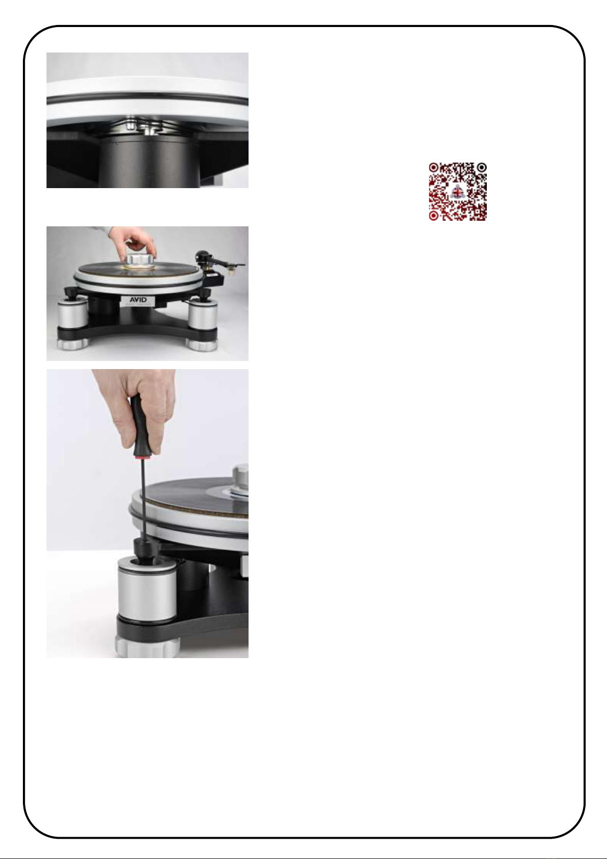
4. The platter surface (mat) is a specially cork/rubber composite, optimised to reduce vibration within the record and
is bonded to the platter. You should not try to remove it, or fit another mat over the top as this will stop the
clamp/bearing for working effectively.
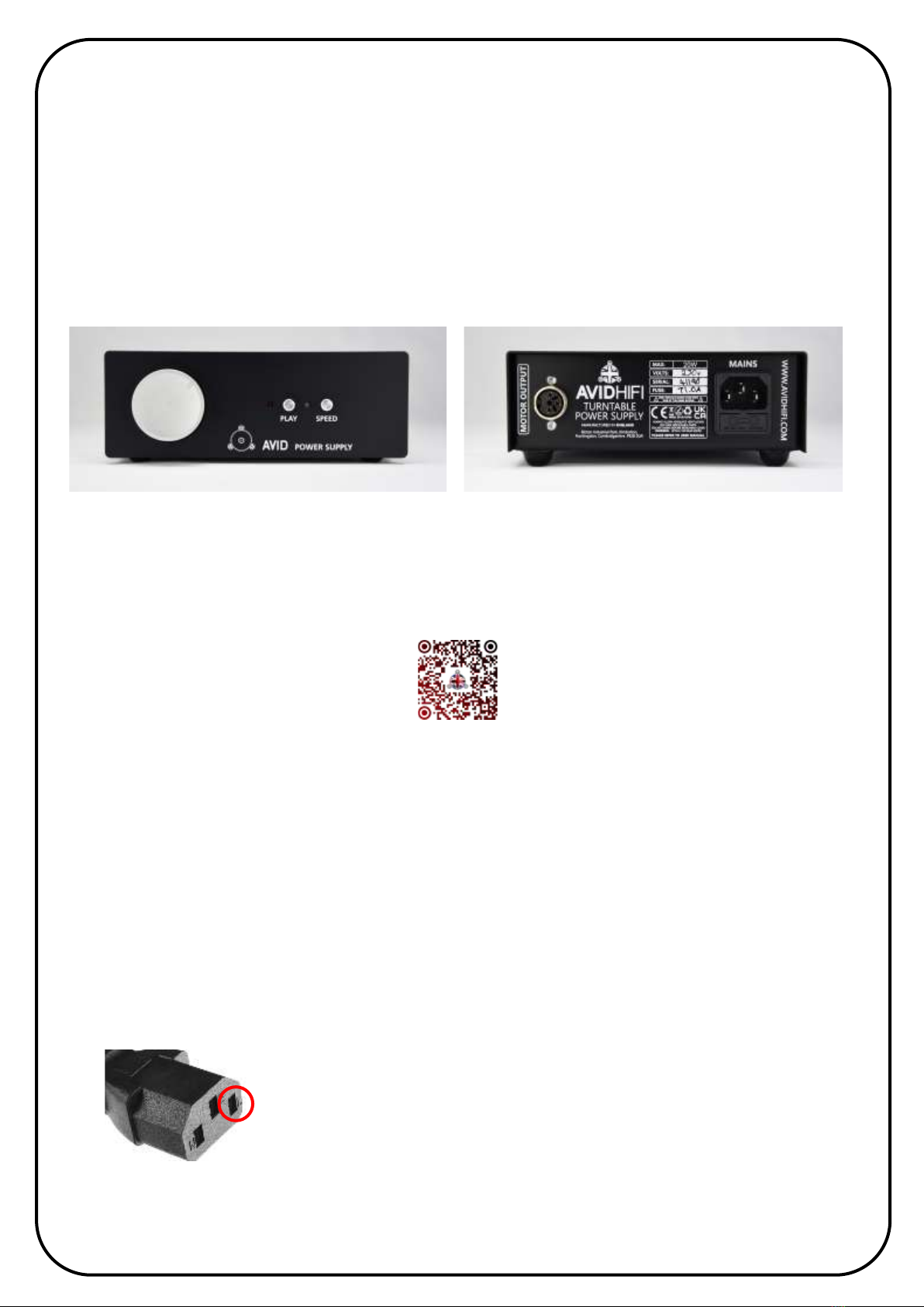
5. The Power Supply contains voltages which can cause serious injury. There are no user serviceable parts inside and
no reason to open it. In situations of failure, return to your dealer or contact AVID directly. There are calibrated
components inside and altering any settings will reduce performance and void the warranty.
6. The motor is a precision mechanism and must under no circumstances be opened or adjusted. If you experience
what you believe to be a problem, consult your dealer or AVID directly.
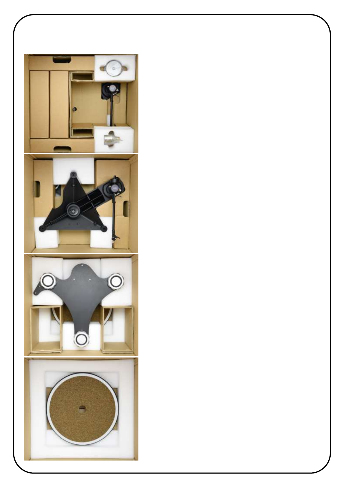
Packaging
The packaging is very expensive to replace, so save all the packing in a dry place away from fire hazard.
The AVID Turntable is a precision instrument and the packaging has been especially designed so that all component parts
are safe during transportation. If you should need to return your unit for upgrade, service or repair, you will be required
to use its original packaging to keep it from damage. In the event of the packing being lost or damaged further packing
can be provided at cost.
Do not transport the turntable assembled. This will cause damage and void the warranty.
Parts Check List
The packing is designed to eliminate parts being missed, however if something is found amiss please contact your dealer.
Instruction Manual 1Drive Belt 2Suspension Lateral O-Ring 3
Platter 1Main Bearing 1Wrench Key Size 3mm A/F 1
Sub-Chassis 1Belt Pin 14mm Tungsten Carbide Ball 1
Clamp 1Power Supply 1Power Cord 1
Main Chassis 1Tonearm (if supplied) 1Cartridge (if supplied) 1

5
Set Up Instructions
The supplied packaging is vital for protection and shipping. It should be retained as replacement packaging is costly.
The packaging is layered with each part having a suitable compartment. Make sure it is fitted correctly to avoid damage.
LAYER 1:
Clamp, Bearing and Power Supply
First, remove the Power Supply to prevent it inadvertently dropping and
then lift out layer 1 using hand holes.
The packaging is designed to allow some tonearms to be pre-mounted
during transportation. If no tonearm is fitted, the suspension is factory
adjusted for a 800g tonearm. Further adjustment may be required on
final installation.
(Arm shown for illustration purpose only)
LAYER 2:
Subchassis and optional arm/cartridge if fitted.
Lift out by using the hand holes at the side.
Power cord and accessory pack.
LAYER 3:
Main Chassis.
Remove Main Chassis including the white foam packaging.
Remove foam and protective cover bags.
LAYER 4:
Metal Platter.
Remove from packaging.
PLEASE REMEMBER THAT THIS IS HEAVY

6
All our suspended turntables offer the opportunity to set up the arm/
cartridge off the suspension. This gives more stability and accuracy.
Place the subchassis on a suitable surface and install the pick up arm
and cartridge if not already fitted.
CLEAN THE TOP OF THE SPINDLE WITH CLEAN TISSUE PAPER
Place the clean bearing ball into the top of the spindle.
This part of the bearing must always be kept clean and free of oil.
DO NOT USE GLUE OR ANY LUBRICATION AS THIS WILL DAMAGE
THE BEARING AND THE PLATTER WILL NOT ROTATE CORRECTLY
CAREFULLY LOWER THE MAIN BEARING ONTO THE SPINDLE
Take special care not to not drop or bang the onto the shaft, otherwise
you will damage the sapphire, which is not covered by warranty.
The bearing will lower quickly due to the air pressure release hole.
NEVER ADD ADDITIONAL BEARING LUBRICATION
Slowly lower the platter onto the main bearing, making sure the spindle
does not scrape or mark the tapered bore in the platter.
USE EXTREME CARE
DO Not to drop or impact the platter onto the bearing as this could
damage the sapphire bearing.
To remove the platter hold at edges and gently rock while lifting to
release from main bearing, taking care not to lift the bearing itself.
If you have bought an AVID tonearm and cartridge, we provide an
alignment gauge specifically designed for setting up your equipment
accurately. You should refer to the instructions provided in the tonearm
manual or seek assistance from your dealer.
However, if you are using a different tonearm, you will need to install a
record and clamp and use the alignment gauge provided with the
chosen tonearm. Once done, you can remove the clamp and record and
proceed to cautiously disassemble the platter and bearing for
installation onto the main chassis and suspension.
The Main Chassis should ideally be placed onto a hard level surface,
such as a typical audio equipment rack and ideally a wall mounted shelf
if you have a bouncy suspended floor which will reduce unwanted
suspension movement. The feet can be adjusted for fine levelling.
If not already factory fitted, install the suspension O-Rings by stretching
them over the suspension housing and into the location groove.

7
Carefully fit the subchassis to the main chassis, locating the subchassis
legs into the suspension adjusters in the middle of each of the springs.
Take care that the subchassis does not tip off due to the weight of the
fitted tonearm. You can apply some downwards pressure to the
subchassis making sure the legs are fully inserted.
Take care the bearing ball does not fall out when fitting the subchassis.
Now stretch each of the lateral suspension O-Rings over the
corresponding fixing on the subchassis underside.
To install the drive belts, you must first attach them to the platter using
the designated belt fitting pin.
Turn the platter over so that the top side is facing down. Locate a small
hole on the rim of the platter. Once you have identified the hole, insert
the belt fitting pin.
It is essential to have clean hands when handling the drive belts, and
also recommended that you clean the platter drive hub and motor drive
pulley before installing the belts. Using isopropyl alcohol cleaner is
suitable for this purpose.
Carefully stretch each of the two belts over the hub and onto the fitting
pin one at a time, ensuring that they aren't twisted together.
Gently fit the platter onto the bearing, taking care not to scrape the
spindle onto the platter bore.
Ensure that the fitting pin is positioned over the motor drive pulley, as
this will simplify the process of installing the drive belts.

8
With a gentle touch, lift the platter edge to expose the motor pulley.
Rotate the platter to engage the belts with the grooves of the drive
pulley. Using your finger, hold the drive belts against the underside rim
of the platter, and then remove the fitting pin. Finally, let go of the drive
belts, and they will be secured in place.
DO NOT SWITCH THE TURNTABLE ON
WATCH OUR BELT FITTING VIDEO:
Now fit the clamp and a record and manually rotate the platter SLOWLY
by hand to align the drive belts correctly, otherwise the lower belt will
fall off if you just push PLAY as the belts hunt for alignment.
Keep the clamp and record fitted, so that the correct mass is loaded
onto the springs to accurately adjust the suspension.
SUSPENSION SET UP AND ADJUSTMENT
With the Main Chassis ideally on a level surface, the turntable platter in
turn should be approximately parallel, however THIS IS NOT CRITICAL
and other factors are more important to obtaining best performance.
Once set up, the platter complete with record and clamp should bounce
with a smooth piston type movement, the drive belts running without
any flicking movement. You can easily see this by looking underneath
the platter whilst it’s running.
As a starting point, level all the suspension posts with the main chassis
posts. This is done by inserting the supplied Allen wrench into the hole
on the subchassis suspension post, pushing down to engage the wrench
and turn clockwise to lower or anticlockwise to raise the suspension
point. Some fine tuning is always advisable, but once correctly adjusted,
the springs self-lock in position and should not require readjustment.
DRESSING THE ARM LEAD
Proper cable management is crucial for the suspension to function correctly. If the tonearm lead is too stiff or improperly
dressed, it can hinder the suspension's movement. Therefore, it is crucial to dress the leads in a way that allows the
suspension to work unimpeded.
The main chassis features a cable clamp that should be used to secure the cable and prevent it from being pulled
inadvertently. However, be careful not to over-tighten or crush the cable while clamping it in place.
After ensuring that the suspension is working correctly, you can clamp the cable in place. If possible, it is recommended
to leave the lead unattached, as long as it does not affect the suspension. Avoid using thick, heavy, or stiff leads, as they
can negatively impact the suspension's performance.

9
Power Supply
The Volvere Power Supply is purpose designed and individually calibrated to the powerful motors used. You should
have no reason to open the power supply and tamper with anything within. Doing so invalidates any warranty, reduces
sound quality and will possibly cause damage. It is important to allow adequate ventilation. The Mains input socket for
all units is an IEC type socket on the rear panel and you should use the cable provided or a suitable alternative. We do
not recommend using mains filters and suggest plugging directly into the mains supply. It is recommended that when
not in use the unit be switched off, as this will extend the life of the internal components.
There is no sonic benefit in leaving the unit permanently switched on.
VOLVERE PSU
Front Panel:
Mains on/off switch (rotate clockwise); Power Light;
PLAY/STOP button; Speed changed button.
Speed indication LED will shine Green for 33rpm and
Amber for 45rpm.
Rear Panel:
Motor Connection - Mains Socket - Fuse Holder
Speed Adjustment: (watch our video guide)
The speed is calibrated at the factory, however you many wish to check this sometimes, although there should be no
drift from the locked speed. To check the speed you will need a strobe disc or alternative.
With the turntable playing, select which speed you wish to adjust and press and hold both PLAY and SPEED buttons
together until the speed light flashes. The flashing light indicates adjustment mode is selected.
Pressing the PLAY button slows the platter and the SPEED button increases the speed. Once correct speed is achieved
press both buttons again to lock.
DO NOT SEE HOW FAST OR SLOW YOU CAN ADJUST THE SPEED AS THIS WILL OVER-LOAD THE SUPPLY
AND IT WILL POSSIBLY BECOME FAULTY. THIS DAMAGE IS EXCLUDED FROM OUR WATTANTY.
For users who have to use two-pin mains sockets, please note that on a standard IEC
mains female plug, the right hand pin (see image) is the ’Live’ pin—always make sure
this is connected to the live pin on the wall socket. Failure to do so will mean that the
neutral feed will pass through the mains switch rather than the live feed , which is less
safe and should be avoided.
Replacement Fuse Guide Volvere PSU
220~250v T1.0A slow blow
100~120v T2.0A slow blow

10
Specifications
VOLVERE TURNTABLE
DRIVE TWIN BELT
SPEEDS 33/45 RPM
PLATTER MASS 6.7 Kg
BEARING Inverted Stainless Steel
THRUST POINT Tungsten Carbide/Sapphire
SUSPENSION 3 Point, frequency adjustable springs in vertical, O-Ring lateral
TONEARMS SME fitting. Adapters available for single or twin tonearms
MOTOR 24v 55mNm AC Synchronous
DIMENSIONS (overall) 425 x 370 x 205mm (WxDxH) (footprint) 375 x 325mm (WxD)
NET WEIGHT 12.5 Kg (27lb)
PACKAGING 450 x 480 x 500mm (WxDxH)
POWER SUPPLY
DIMENSIONS 153 x 283 x 60mm (WxDxH)
NET WEIGHT 2.2 Kg (5lb)
VOLTAGE INPUT 100-240VAC 20 Watts max. (depending on region)
AVID reserves the right to improve or change its products without notice at any time.
Servicing
General servicing is not required, however we do offer a maintenance service, see our website upgrades page.
Drive Belts we recommend replacing bi-annually or sooner if you use the turntable every day.
Cleaning
To maintain the visual appearance, occasionally dust the surfaces with a normal microfiber cloth - no need for any
sprays or polishes. Fingerprints, greasy marks or similar smudges can be removed with a damp cloth with mild
soapy water or isopropyl alcohol cleaner. Never use cleaners containing abrasives, as this will damage the surface.
EC DECLARATION OF CONFORMITY
We the Manufacturer, AVID HIFI Limited
Bicton Ind. Park, Kimbolton, Cambridgeshire. PE28 0LW (UK)
TEL: +44 (0)1480 869900 / Email: i[email protected] / Web: www.avidhifi.com
Acknowledge our sole responsibility, that the product:
KIND OF EQUIPMENT: Turntable/Record Player TYPE DESIGNATION: VOLVERE (All Variants)
In accordance with the EMC Directive 2014/30/EU is in compliance with the following norm(s) or document(s):
Technical regulations: EN 55032:2015+AC:2016 / EN 55035:2017 EN 61000-3-2:2014 / EN 61000-3-3:2013
&
In accordance with the Low Voltage Directive 2014/35/EU is in compliance with the following norm(s) or document(s):
Technical regulations: EN 62368-1:2014
&
Is in conformity with Directive (EU) 2015/863 Restriction of Hazardous Substances in electrical and electronic equipment.
Conrad Mas (Managing Director)
Date: 4th January 2021

11
Warranty Statement
UK Residents
AVID HIFI Limited products are warranted against defects in materials and workmanship for a period of two years from the
original date of purchase, or no later than three years from the date of shipment to an authorized AVID agent, which ever
comes first, extending to five years subject to the product owner having submitted the Registration form
www.avidhifi.com/register
Also the following conditions being observed.
• The product must have been purchased through an authorized AVID dealer
• This warranty is in favour of the original purchaser only, except where...
• Warranties are transferable to subsequent owners provided the new owner completes the product registration form.
Warranty obligation is passed from dealer to manufacturer.
• During the warranty period, AVID will repair, or replace any defects in material or workmanship, without charge for
parts or labour.
• Should product need to be returned a written description of the defect and a photocopy of the original purchase receipt
must accompany it. Receipts must show the model, serial number, date of purchase, name and address of purchaser and
authorized dealer and the price paid.
• Returned product must be packed in the original packing and returned to AVID or original dealer by the customer at
his/her expense. AVID will pay return freight of its choice.
• The warranty is void if the product has been used or handled other than in accordance with the instruction manual
supplied, abused or misused, damage by accident or neglect or in being transported, or the defect is due to the product
being repaired or tampered with by anyone other than AVID or an dealer with prior authorization.
• The warranty is void if the product serial number has been removed, altered or made illegible.
• The warranty is void if the product has been taken out of the country of purchase.
• AVID shall not be held liable for incidental or consequential damages of any kind arising from the sale or use of
its products.
• The warranty applies to ex-demonstration product, using manufacture date as purchase date.
• Where the product is sold under a consumer transaction (as defined by the Sale of Goods Act 1979) the statutory rights
of the purchaser are not affected by this warranty.
• Products are sold on the basis of specifications applicable at the time of sale. AVID shall have no obligation to modify
or to update products once sold.
Outside UK
• AVID has formal distribution in many countries throughout the world. In each country the AVID importer has contractually
accepted the responsibility for the product warranty. Warranty should normally be obtained from the importing agent or
distributor from whom you obtained your product. In the unlikely event of service required beyond the capability of the
importer, AVID will, of course, back up the warranty.
• Where product has been either supplied directly or there is no current distributor, AVID accepts responsibility for the
warranty period.
• Returned product must be packed in the original packing and returned to AVID by the customer at his/her expense. AVID
will pay return freight of its choice.
• The warranty is only valid in the country of purchase.
• Products outside there original destination requires that units with remaining warranty be returned to the country of
purchase for the warranty to be valid. Customer is responsible for freight both ways and all associated import and
export charges.
• Foreign distributors are not required to provide warranty service, repair or change AC mains voltage on units that they
did not originally import and sell.
• Foreign distributors may at their discretion offer service for a fee.
MISCELLANEOUS. ANY IMPLIED WARRANTIES RELATING TO THE ABOVE PRODUCT SHALL BE LIMITED TO THE DURATION OF THIS WARRANTY.
THE WARRANTY DOES NOT EXTEND TO ANY INCIDENTAL OR CONSEQUENTIAL COSTS OR DAMAGES TO THE PURCHASER.
WARRANTOR. Inquiries regarding the Limited Warranty may be sent to the following address:
AVID HIFI Limited. Bicton Industrial Park, Kimbolton, Huntingdon. PE28 0LW ENGLAND

12
AVID HIFI Ltd
Bicton Industrial Park,
Kimbolton, Huntingdon,
Cambridgeshire.
PE28 0LW
ENGLAND
Tel: +44(0)1480 869 900 — Website: www.avidhifi.com - Email: info@avidhifi.co.uk
V230308
Table of contents
Other AVID HIFI Turntable manuals

AVID HIFI
AVID HIFI Ionic User manual

AVID HIFI
AVID HIFI Naim Slide User manual

AVID HIFI
AVID HIFI DIVA II SP User manual

AVID HIFI
AVID HIFI ACUTUS User manual

AVID HIFI
AVID HIFI DIVA II SP User manual

AVID HIFI
AVID HIFI Ingenium Series User manual

AVID HIFI
AVID HIFI Ingenium P&P User manual

AVID HIFI
AVID HIFI DIVA II SP User manual