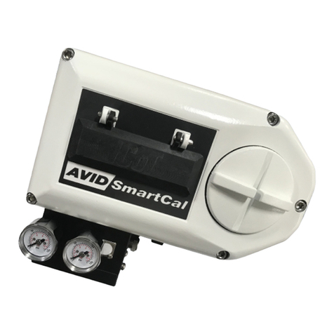
Avid Technology SmartCal Series User manual

AVID
AVDSB-0026-EN-1307
Contents
1 Introduction 2
1.1 Description of SmartCal positioner 2
1.2 Principle of operation 2
2 Initial setup 4
2.1 Mounting positioner on a rotary
actuator 4
2.2 Mounting remote positioner on a
rotary actuator 5
2.3 Wiring the remote sensors to the
positioner 6
2.4 Mounting positioner on a linear
actuator 7
2.5 Mounting remote positioner on
alinear actuator 9
2.6 Pneumatic connection 10
2.7 Electrical connection 11
3 Calibration with the display 12
3.1 Enter calibration 12
3.2 Configure the positioners
parameters 12
3.3 Automatic calibration 13
3.4 Advanced calibration (optional) 13
3.5 Exit calibration 14
3.6 Manual override of input signal 14
3.7 Description of menus 15
3.8 Description of functions 16
4 Calibration with pc application 18
4.1 Configuration of the SmartCal
parameters 19
4.2 Measurement data 20
4.3 Diagnosis 21
4.4 Additional functions 22
4.5 Print 23
5 Trouble shooting 24
5.1 Preliminary checks 24
5.2 FAQ 25
6 Specifications 26
7 Error codes 26
8 Exploded parts list 27
Appendices
A Procedure to adjust Err 3 setting 28
B Procedure to remove electronics
cover and electronic canister 29
C Setting the transmitter output
failcurrent 30
AVID SmartCal valve positioner
Installation & operating instructions
Installation and operating instructions for the AVID
SmartCal intelligent valve positioner
Note: Air supply to the positioner
mustbe clean, dry, oil free instrument
air(5microns) per ISA-S7.3 and
ISO8573-1. Maximum supply pressure
is 8.3 bar. Allpneumatic connections
are1/4” NPT or G 1/4 ISO 228.
www.cranecpe.com
D Procedure to check transducer
operation 31
E General maintenance standard
flow 32
F Grounding schematic 33
G Pneumatic manifold diagram 34
H Control schematic for wiring of
intrinsically safe SmartCal for
ATEX&IECEX 35
I Control schematic for wiring of
intrinsically safe SmartCal for
US&Canada 37
J Procedure to reset the EEPROM
tofactory settings 41
K HART® Communicator menu
flowchart 42

page 2
1 Introduction
1.1 Description of SmartCal positioner
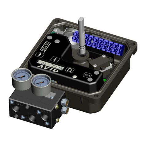
The SmartCal valve positioner is an electro-pneumatic servo system that continuously controls the
position of a valve based on a 4 to 20 mA input signal. The SmartCal is an instrument that
derives its power directly from a control systems current loop. The instrument senses valve
position via a non-contact Hall effect sensor and controls valve position through a current to
pressure transducer.
Calibration of the SmartCal can transpire by two means. Non-HART® calibration is through an
on-board keypad. Communication using HART® protocol allows calibration and access to on-line
diagnostics via a Rosemount® 275 hand-held terminal or through FDT/DTM software.
The positioner has a local liquid crystal display which indicates valve position and set-point in
percentage open. It also indicates whether the positioner is in calibration mode.
The SmartCal has the capability to monitor operation. If a failure condition occurs, an error
message is displayed on the local liquid crystal display.
1.2 Principle of operation
Unlike conventional positioners, the SmartCal positioner feeds back valve position without the
need for linkages, levers, or rotary and linear seals. Position sensing is performed totally by
non-contacting means, permitting use of advanced control strategies where knowledge of valve
position is used in predictive and other algorithms. By the integration of multiple components into
a singular, cost efficient unit, microprocessor-based intelligence can now be used to implement
advanced functions such as early warning diagnostics and fugitive emissions monitoring.
The SmartCal positioner provides intelligence for the control valve through a microprocessor-based
diagnostic system utilizing the HART® protocol. Accurate measurement of valve stem position,
input signal, actuator pressure and travel time can be recorded during normal operation, thereby
providing information for control valve signature generation.
AVID SmartCal valve positioner
Installation & operating instructions
LINEAR VALVE
Magnet
Magnet
Sensor
Magnet
Valve stem
Sensor
Magnet

Non-contact position feedback
To provide consistently accurate performance information, all linkages, levers and connecting rods,
from the positioner to the control valve have been eliminated from the design. Valve position sensing
is performed totally by non-contacting means based upon characterisation of flux strength as a
function of position.
Remote position control
Since valve position feedback to the SmartCal positioner is accomplished by non-contacting means,
the SmartCal has the unique ability to be mounted remotely (up to a distance of 15 m or 50 feet)
from the device it is controlling. In the event the control valve is located in either a high vibration
or extremely corrosive environment, the non-contact position feedback feature allows for isolated
placement of the positioner.
Local LCD
The SmartCal positioner is supplied with HART® interface and a 3-button keypad interface. All
SmartCal positioners are furnished with a multi-line LCD, and allow for automated calibration of
the positioner. The local LCD provides a multitude of onsite diagnostic information. The displayed
information will show the setpoint and position as a percentage. The range of values displayed are
from 0.0% to 100.0%. Displayed resolution is in 0.1% increments, however, internal calculations
are maintained at higher precision.
On-board sensors
The SmartCal positioner has the capability to monitor its operation. If an error or failure condition
occurs, it will be displayed on the local LCD, through the HART® interface and displayed on a hand
held terminal or at a PC maintenance station. Note: Error codes are denoted on a label affixed to
the LCD flip-up protective cover.
Local keypad
All positioners are provided with a 3-button keypad. The keypad is provided for zero and span
adjustments, as well as valve characterization and gain adjustments.
Intelligent calibration (HART® protocol)
The SmartCal positioner responds to HART® commands for seeking the ‘valve closed’ position
and assigns an instrument signal of 4 mA to this position. The counterpart of the operation for a
full open state is implemented next by setting the span value. Action reversal is also configured.
Additionally, provisions are made for altering internal servo loop tuning via the HART® link. In
this manner, positioner performance may be optimized with a wide combination of valves and
actuators.
Negligible bleed
Designed to consume the least possible amount of control air at steady state, the SmartCal
positioner can greatly reduce the air consumption of your process and reduce the demand on
instrument air compressors. To increase reliability, the SmartCal employs a patented lapped spool
and floating sleeve design. This balanced construction relies on an air bearing which eliminates
any metal to metal contact.
page 3
AVID SmartCal valve positioner
Installation & operating instructions

page 4
AVID SmartCal valve positioner
Installation & operating instructions
2 Initial setup
Condition 2:
Actuator fails in a counter clockwise direction
(Turns clockwise from fail position).
Spring return
Output port 2 is plugged.
Output port 1 is piped to turn the actuator
clockwise.
Double acting
Output port 2 is piped to turn the actuator
counter clockwise.
Output port 1 is piped to turn the actuator
clockwise.
Semi-circle faces
the front of the
positioner
Actuator
(in fail position)
ModMount
Supply
Port 1
Port 2
Triangle faces
the front of the
positioner
Actuator
(in fail position)
ModMount
Supply
Port 1
Port 2
TURNS
COUNTER CLOCKWISE
(from fail position)
TURNS CLOCKWISE
(from fail position)
2.1 Mounting positioner on a rotary
actuator
Condition 1:
Actuator fails in a clockwise direction
(Turns counter clockwise from fail position).
Spring return
Output port 2 is plugged.
Output Port 1 is piped to turn the actuator
counter clockwise.
Double acting
Output port 2 is piped to turn the actuator
clockwise.
Output port 1 is piped to turn the actuator
counter clockwise.
Figure 2-1
* Note
1. Drive insert must be provided with
Keystone actuators for ModMount
installations.
2. Drive insert may need to be disengaged
and rotated 90° to allow for proper
mounting.
* Drive insert
* Drive insert

Condition 2:
Actuator fails in a counter clockwise direction
(Turns clockwise from fail position).
Spring return
Output port 2 is plugged.
Output port 1 is piped to turn the actuator
clockwise.
Double acting
Output port 2 is piped to turn the actuator
counter clockwise
Output port 1 is piped to turn the actuator
clockwise
Semi-circle faces
side with the
conduit entry
Actuator
(in fail position)
Mounting assembly
Conduit entry
Positioner sensor
Triangle faces the
side with the
conduit entry
Actuator
(In fail position)
Mounting assembly
Conduit entry
Positioner sensor
TURNS
COUNTER CLOCKWISE
(From fail position)
TURNS CLOCKWISE
(From Fail Position)
2.2 Mounting remote positioner on a
rotary actuator
Condition 1:
Actuator fails in a clockwise direction
(Turns counter clockwise from fail position).
Spring return
Output port 2 is plugged.
Output port 1 is piped to turn the actuator
counter clockwise.
Double acting
Output port 2 is piped to turn the actuator
clockwise.
Output port 1 is piped to turn the actuator
counter clockwise.
Figure 2-2
* Note
1. Drive insert must be provided with
Keystone actuators for ModMount
installations.
2. Drive insert may need to be disengaged
and rotated 90° to allow for proper
mounting.
* Drive insert
* Drive insert
page 5
AVID SmartCal valve positioner
Installation & operating instructions

page 6
AVID SmartCal valve positioner
Installation & operating instructions
Position sensor
(mounted on actuator
as described in Section 2.2)
2.3 Wiring the remote sensors to the positioner
Mount positioner at a remote location. Remove the electronic canister cover by unscrewing 2
mounting screws. Wire the positioner sensors back to the positioner using the cable provided
(seeFigure 2-3).
(4) Conductor cable
(cut to required length
and run through conduit)
M20x1.5
(1/2” NPT)
Positioner
sensor
HALL
EFFECT
SENSOR
SHIELD (YELLOW)
BLACK
GREEN
RED
WHITE
Pin connector
(to display board
of positioner)
(4) Conductor
shielded cable
3/4” NPT
Wiring schematic
Figure 2-3
Actuator
(top view)
Positioner
(mounted remote from
actuator at users discretion)

1.5 mm (1/16”)
1.5 mm (1/16”)
page 7
AVID SmartCal valve positioner
Installation & operating instructions
Magnet assembly
SmartCal assembly
housing
Centerline of
magnetic pick-up unit
(position sensor)
Actuator split block
(atlower limit of
travel)
Actuator
centerline
Actuator split block
(atupper limit of travel)
Stroke/2
Stroke/2
Full
stroke
Upper limit of travel
Location of centerline
Lower limit of travel
Actuator yoke
Actuator split block
Magnet assembly
Mounting bracket
Magnetic pick-up unit
(position sensor)
SmartCal assembly
2.4 Mounting positioner on a linear
actuator
Step 1. Mount the magnet assembly to the
stem of the actuator. A coupler block normally
is needed to extend the magnet assembly
outside the yoke area and into the sensing
range of the magnetic pick-up unit.
Step 2. Fasten the mounting bracket to the
actuator.
Step 3. Mount the positioner to the mounting
bracket. The positioner should be mounted so
the magnetic pick-up unit of the positioner is
centered between the limits of the magnetic
assembly’s stroke. After mounting the
positioner, the magnet assembly should
be within 3 mm (1/8”) from the back of
the positioner (1.5 mm (1/16”) is ideal),
(SeeFigure2-4 A)
Note
For Fisher actuators model 657 & 667 sizes 34
thru 70, can supply a slotted
mounting kit design. This will allow the user
to easily center the positioner sensor between
the limits of the magnet assembly’s stroke.
Figure 2-4 A

page 8
AVID SmartCal valve positioner
Installation & operating instructions
2.4.1 To center the positioner
1. Stroke the actuator to its upper limit and place a mark on the actuator’s yoke that lines up with
the red arrow on the magnet assembly.
2. Stroke the actuator to its lower limit and place a mark on the actuator’s yoke that lines up with
the red arrow on the magnet assembly.
3. Place a third mark on the yoke centered between the upper and lower limit marks.
4. Lastly, mount the positioner to the bracket so that the positioner sensor (nose) of the SmartCal
lines up with the midpoint mark. (See Figure 2-4 B)
Figure 2-4 B
Magnet assembly
(atupper limit of travel)
Magnet assembly
(atlowerlimit of travel)
Lower limit of travel mark
Midpoint of travel mark
Upper limit of travel mark
Actuator yoke
SmartCal

page 9
AVID SmartCal valve positioner
Installation & operating instructions
Actuator
Mounting bracket
Position sensor
Conduit entry
2.5 Mounting remote positioner on a linear actuator
Step 1. Mount the magnet assembly and bracket to the actuator as described in Section 3.3 Step 1.
Step 2. Mount the position sensor housing so that the conduit entry faces away from the
diaphragm or cylinder. (See Figure 2-5 A)
Step 3. Mount positioner at a remote location.
Note
For Fisher actuators model 657 & 667 sizes 34
thru 70, supplies a slotted mounting
kit design, to ease the mounting process. This
will allow the user to easily center the
positioner sensor between the limits of the
magnet assembly’s stroke.
Figure 2-5

2.6 Pneumatic connection
Single acting actuator (spring return):
For single acting actuators outlet port 2 is to be plugged. Outlet port 1 is to be piped to the
actuator inlet port that acts against the spring. (Increasing control signal causes pressure to
increase in outlet port 1 of the positioner).
Double acting actuator (double return):
For double acting actuators outlet port 2 is piped to drive the actuator towards the fail position.
Outlet port 1 is piped to drive the actuator away from the fail position. (Increasing control signal
causes pressure to increase in outlet port 1 of the positioner and pressure to decrease in outlet
port 2 of the positioner).
Note: Air supply to the positioner must be clean, dry, oil free instrument air (5 microns) per
ISA-S7.3 and ISO 8573-1. Maximum supply pressure is 8.3 bar. All pneumatic connections are
1/4”NPT or G 1/4 ISO 228.
Inlet port gage
Outlet port 1 gage
Outlet port 1
Outlet port 2
Inlet port
1. Single acting/spring return (plug outlet port 2) increasing control signal causes pressure to
increase in outlet port 1.
2. Double acting/double return (pipe outlet port 2 to drive actuator towards the desired failure
direction) increasing control signal causes pressure to decrease in outlet port 2 and pressure to
increase in outlet port 1.
Notes:
On loss of power pressure fails to outlet port 2.
Figure 2-6
page 10
AVID SmartCal valve positioner
Installation & operating instructions

Analog
input
Analog
output
Switch 2
(optional)
Switch 1
(optional)
Simple apparatus
Switch 2 (optional)
Simple apparatus
Switch 1 (optional)
Figure 2-7
2.7 Electrical connection
Warning
1. The certification applies to equipment without cable glands. When mounting the enclosure
in the hazardous areas, only suitably certified cable glands and blanking elements must be
used to maintain ingress protection of IP66.
2. All unused cable entries must be plugged with suitably certified plugs that can maintain an
ingress protection level of IP66.
3. The positioner, switches, sensors and coils shall be electrically connected suitable to the
rated data via a certified isolating interface/zener barrier placed outside the hazardous
areas.
4. For ambient temperatures below -10°C and above +60°C, use field wiring suitable for both
minimum and maximum ambient temperatures.
1. Remove positioner cover.
2. Locate terminal strip and carefully disconnect (slide off).
3. Connect the 4 to 20 mA loop signal to terminal points marked (+) and (-). See Figure 2-7 for a
wiring schematic.
4. If using the analog transmitter, connect output wiring to terminal points 5 & 6, (Polarities shown
below). The 4 to 20 mA analog output requires an external 24 V DC power supply.
5. After all connections have been made reconnect the terminal strip and replace positioner cover.
page 11
AVID SmartCal valve positioner
Installation & operating instructions

3 Calibration with the display
If during the calibration routine you need more information describing any of the menus or
functions refer to Sections 3.7 and 3.8. The SmartCal positioners also has an on-board help menu
that can be accessed by pressing the Cal button and either arrow button simultaneously, anytime
during calibration.
3.1 Enter calibration (Menu level)
Enter the calibration routine by pressing and holding the CAL button. Continue to hold the CAL
button until ACAL appears on the LCD. ACAL (Auto Cal Menu) is the first of four menus. By
pressing the down arrow button you can cycle through the four menus. The remaining three
menus are MCAL (Manual Cal Menu), Cofg (Configuration Menu), Stro (Manual Position Override
Menu). The menu level is shown below.
Normal operation
(‘OK’ displayed on LCD)
Up arrow
(exit calibration)
Down arrow
(from previous menu)
Down arrow
(to next menu)
Up
arrow
Up arrow
Down Down Down
Down
Down
Down
Down
Down
Down
Quick
opening
flow
Equal
percentage
flow
Rotary
valve
Fail
open
Use up
& down
arrows
to select
open
speed
01 = slow
05 = fast
Use up
& down
arrows
to select
close
speed
01 = slow
05 = fast
Use up
& down
arrows
to adjust
deadband
Linear
valve
Fail
close
Deadband
at ± 5%
Up
arrow
Down
arrow
Down
arrow
Down
arrow
Down
arrow
Down
arrow
Down
arrow
(See Section 3.3) (See Section 3.4) (See Section 3.2) (See Section 3.6)
Down
arrow
Down
arrow
Down
arrow
Up
arrow
Up arrow
Press & hold CAL
key until ‘ACAL’
appears on display
3.2 Configure the positioners parameters
From the Menu level press the down arrow button until the Cofg (Configuration Menu) is shown
on the display (configuration routine shown below). Enter this menu and change any of the
parameters, if other than the factory settings are needed. The factory settings are highlighted.
Up arrow Up arrow Up arrow Up arrow Up arrow
Linear
flow
Down
arrow
page 12
AVID SmartCal valve positioner
Installation & operating instructions

FINE TUNE
Up arrow
(exit calibration)
Set 12 mA
Press CAL Key
Down arrow
(from previous menu)
Down arrow
(to next menu)
Down
arrow
3.3 Automatic calibration
The automatic calibration (ACAL) performs several self-adjustments, as well as a zero calibration,
a span calibration, and tunes the positioners PID gain settings. Enter and start the automatic
calibration from the menu level. From the menu level press the down arrow button until ACAL is
shown on the display (ACAL routine shown below).
Note: Automatic calibration requires an input current of 12 mA.
Auto calibrate* * 1. Sensor calibration
2. Low span calibration
3. High span calibration
4. Transducer calibration
5. Auto PID calibration
3.4 Proceed to exiting calibration or perform advanced calibration
At this point the calibration of the positioner is complete. The automatic calibration that was
performed in Section 3.3 is adequate for most applications. If no advanced calibration is required
proceed to Section 3.5 to exit calibration. If the user requires to use the advanced settings to fine
tune the positioner he may proceed with the remainder of this step and perform adjustments and
calibrations in the Manual Calibration Menu (MCAL). From the menu level press the down arrow
button until MCAL is shown on the display (MCAL routine shown below).
Up arrow
(exit calibration)
Down arrow
(from previous menu)
Down arrow
(to next menu)
Up arrow
Down
arrow
Up arrow
Up arrow
Up arrow
Up arrow
Up arrow
Press CAL key
Press CAL key Press CAL key
Press CAL key
Press CAL key Press CAL key
Press CAL key
Press CAL key
Press CAL key Press CAL key
Press CAL key
when complete
Press CAL key Press CAL
key
Set 12 mA
Press CAL key Set 12 mA
Press CAL key Press CAL key
Press CAL key
Press CAL key
Press CAL key
Press CAL key
Press CAL key
Press CAL key
when complete
Press CAL key
when complete
Press CAL key
when complete
Press CAL key
when complete
Press CAL key
Down
arrow
Down
arrow Down
arrow
Down
arrow
Press CAL key
Down
arrow
Down
arrow
Down
arrow
Down
arrow
Down
arrow
Down
arrow
Down
arrow Down
arrow
Down
arrow
Set mA for
zero position
Set mA for
span position
Sensor
calibration
Transducer
calibration Set 4.0 mA
Use up & down arrow
keys to set to zero
input current
Set 20.0 mA
Use up & down arrow
keys to set to span
input current
Low/zero
calibration
Span
calibration
Automatic
PID routine Adjust using
up & down
arrow keys
(1-20)
Adjust using
up & down
arrow keys
(1-255)
Adjust using
up & down
arrow keys
(1-5)
Adjust using
up & down
arrow keys
(1-255)
Adjust using
up & down
arrow keys
(1-255)
Adjust using
up & down
arrow keys
(1-20)
Optional:
select arbitrary
zero using up &
down arrow keys
Optional:
select arbitrary
span using up &
down arrow keys
Read transmitter
value & use up &
down arrows to
enter the present
zero value
Use up & down
arrows to enter the
desired zero current,
typically 4.0 mA
Read transmitter
value & use up &
down arrows to
enter the present
span value
Use up & down
arrows to enter the
desired span current,
typically 20.0 mA
Special note flow capacity
SmartCal standard flow design is suitable
for actuator swept volumes of a minimum
40 inch3(0.65 liters) to a maximum of 600
inch3(9.8 liters) for proper auto calibration
functionality. It should also be noted that
this is to be used as a general guideline only.
The actuator/ valve package dynamics would
dictate the success of the auto calibration
routine and could be compromised by the
following: instrument air supply volume
capacity, actuator sizing, tubing size and
actuator/valve health.
SmartCal optional high flow design is suitable
for actuator swept volumes of a minimum
200 inch3(3.3 liters) to a maximum of 1000
inch3(16.4 liters) for proper auto calibration
functionality. It should also be noted that
this is to be used as a general guideline only.
The actuator/ valve package dynamics would
dictate the success of the auto calibration
routine and could be compromised by the
following: instrument air supply volume
capacity, actuator sizing, tubing size and
actuator/valve health.
OFF
Press CAL key
ON ON OFF
page 13
AVID SmartCal valve positioner
Installation & operating instructions

3.5 Exiting calibration
To exit calibration mode and return to normal operation use the up arrow key as follows:
• If the positioner is at menu level in the calibration, as determined by LCD displaying a menu name
only (MCAL, etc.), press the up arrow key once to exit CAL mode.
• If the positioner is at function level in the calibration, as determined by LCD displaying a function
and menu name only (MCAL Lo, etc.), press the up arrow key once to enter the menu level and
once more to exit CAL mode.
• When the calibration mode is exited the menu and function names will no longer be displayed by
the LCD. The LCD will be displayed ‘OK’.
Exiting can not be done during a calibration procedure. When a calibration function is initiated, the
user must wait until the function’s calibration is complete before being able to exit calibration.
The up arrow key can be used, as described above, to move to the Menu level and then to exit
CALmode.
3.6 Manual override of input signal (via on-board keypad)
The positioner has a feature which allows the operator to override the analog signal and change
valve position of the SmartCal. This is done from the Stro (manual override stroke menu). Enter
calibration as described in section 3.1 and use the down arrow button to cycle to the Stro menu.
Enter this menu and control the position of the valve as shown below.
Up arrow
(exit calibration)
Down arrow
(from previous menu) Down arrow
(to next menu)
Down
arrow Down
arrow Down
arrow
UP UP UP
Slow
move
Press &
hold up
or down
arrow
valve will
move
0.1%
Valve
full open
Use up
& down
can
move
valve
slowly
Fast
move
Press up
or down
arrow
one time
valve
moves
5%
Valve
closed
Use up
& down
can
move
valve
slowly
AVID SmartCal valve positioner
Installation & operating instructions
page 14

3.7 Description of menus
The calibration functions of the SmartCal positioner is organized into the following four menus:
Menus
• Menu 1: ACAL (Automatic calibration)
• Menu 2: MCAL (Manual calibration)
• Menu 3: Cofg (Configuration)
• Menu 4: Stro (Manual override of input signal)
Menu descriptions are as follows:
Menu 1: ACAL (Automatic calibration)
Entering this menu allows you to initiate an approximately seven minute self-calibration function.
The SmartCal positioner will automatically enter digital control mode and perform a shallow (input
current 12 mA recommended) calibration in the following sequence:
Function
1 - Snsr - Sensor calibration
2 - Lo - Low (zero) calibration
3 - Hi - High (span) calibration
4 - Trnd - Transducer calibration
5 - Auto - Automatic PID tuning
Menu 2: MCAL (manual calibration)
Entering this menu allows you access to the following seven calibration functions via the keypad:
1 - Lo - Low (zero) calibration
2 - Hi - High (span) calibration
3 - PID - Proportional, integral and derivative gain adjustment
4 - Snsr - Sensor calibration
5 - Trnd - Transducer calibration
6 - mA - Milliampere calibration
7 - Xmr - Transmitter calibration
Menu 3: Cofg (configuration)
Entering this menu allows you access to the following five configuration functions via the keypad:
1 - Flow - Positioner output flow characteristics
2 - Type - Positioner recognition of magnetic feedback, rotary or linear
3 - Flop - Positioner fail position, open or closed
4 - OPSP - Positioner opening speed adjustment
5 - CLSP - Positioner closing speed adjustment
6 - EDb - Positioner operating deadband adjustment
7 - LCD - LCD menu timeout adjustment
These functions allow display, speed and valve characteristic changes from standard factory settings.
Menu 4: Stro (Manual override of input signal)
Entering this menu allows you access to the following three stroking functions via the keypad:
1 - Adjs - Adjustment of positioner to any position using keypad arrows
2 - OP - Open, sets the valve to the full open position
3 - CLs - Close, sets the valve to the full closed position
These functions set the positioner to digital control mode (input current independent) and therefore
allow override of the control signal.
page 15
AVID SmartCal valve positioner
Installation & operating instructions

3.8 Description of functions
LO This function serves to set the fail position of the actuator/valve. Initially during this
calibration the valve is driven to the fail position (hard stop). The user will notice full
pressure to outlet port 2 and zero pressure to outlet port 1. After a short period of time
pressure will increase in outlet port 1 and the valve will be driven to the fully energized
position and the back to the fail position. The calibration is making note of the torques
required to fully seat and un-seat the valve from the hard stop. At this point the user has
the option to select the hard stop as low (zero) position or to select an arbitrary position as
low (zero) position.
HI This function serves to set the fully energized (full travel) position of the actuator/valve.
Initially during this calibration the valve is driven to the fully energized (full travel) position
(hard stop). The user will notice full pressure to outlet port 1 and zero pressure to outlet
port 2. After a short period of time pressure will increase in outlet port 2 and will be driven
off of the hard stop. At this point the user has the option to select the hard stop as the
high (span) position. or to select an arbitrary position as the high (span) position.
PID The PID function allows the user to enter or change the PID settings of the positioner.
This function is most often used to fine tune the PID values obtained from the automatic
calibration function (ACAL). This function will allow the user to optimize the dynamic
response of the positioner with respect to speed of response, overshoot and percent
error by varying the appropriate gain settings. The fine tune proportional (PCAL) and
derivative (DCAL) and integral (ICAL) gain settings can be varied incrementally on a scale
from 1-255. The manual proportional (PCAL) and derivative (DCAL) gain settings can be
varied incrementally on a scale from 1-20. The integral (ICAL) gain setting can be varied
incrementally on a scale from 1-5. The manual values are index representations of the fine
tune settings that are reported through the HART® communication. The larger the number
the higher the gain setting.
Snsr The sensor calibration is a self adjustment that sets the positioners Hall-effect circuitry.
This is automatically done during the ACAL (automatic calibration) routine. The sensor
calibration also shows up under the MCAL menu. This calibration only needs to be
performed under the MCAL routine when the positioner is set-up on a new application
and only if the ACAL routine is not performed.
trnd The purpose of this function is to calibrate the positioner’ s transducer. The transducer is
calibrated on all new positioners at the factory, therefore this procedure does not need to
be performed for a new positioner. Perform this calibration function only if a replacement
transducer or electronic canister was installed in the positioner.
-mA- This routine calibrates the positioner’ s electronics to recognizing input current. This is
done using 4.0 mA and 20.0 mA as reference points. If exactly 4.0 mA or 20.0 mA can
not be given as inputs, the user can adjust the positioners values to the input using the
arrow buttons.
Xmr This routine calibrates the positioner’ s transmitter. The transmitter calibration does not
require the user to change the input current, although it does require the user to be
able to read the transmitter’ s value in mA. For each, the zero and span, the user is first
prompted to enter the value that the transmitter is presently at. This is done by using the
up and down arrow buttons. The user is then prompted to enter the desired transmitter
output (typically 4.0 mA for zero and 20.0 mA for span). The positioner then calculates the
difference between the present and the desired output currents (for zero and span) and
uses the differential to adjust the transmitter accordingly.
Flow This function allows for the setting of the flow characteristic of the positioner (not to be
confused with the flow characteristic of the valve). The options are Lin (Linear), EP (Equal
Percentage) and Opn (Quick Opening). A Lin (Linear) positioner characteristic duplicates
the inherent characteristic of the valve and is the most often used setting.
Type This function configures the positioner for the type of valve. The options are rot (rotary)
and lin (linear). This setting needs to be done in order to configure the positioner to
recognize the type of magnetic feedback being given to the positioner.
AVID SmartCal valve positioner
Installation & operating instructions
page 16

FLOP This function allows the user to configure the positioner to match the failure method
of the valve/actuator. The options are ‘off’ or ‘on’. The ‘off’ option is for fail closed
applications and the ‘on’ option is for fail open application. When ‘off’ is chosen the
LCD will read 0% at the zero (Lo calibration) and 100% at the span (Hi calibration). When
‘on’ is chosen the LCD will read 100% at the zero (Lo calibration) and 0% at the span (Hi
calibration).
OPSP This function allows for the setting of the opening speed of the actuator/valve. The range
is 1 thru 5. Setting 5 is the fastest opening speed and setting 1 is the slowest opening
speed.
Setting Approx.% dynamic speed
5 100%
4 80%
3 60%
2 60%
1 20%
CLSP This function allows for the setting of the closing speed of the actuator/valve. The range is
1 thru 5. Setting 5 is the fastest closing speed and setting 1 is the slowest closing speed.
EDb This feature configures the positioner’ s operating deadband. The configuration options
are ‘off’ and ‘on’. The positioner is factory set as ‘off’. When the deadband feature is ‘off’
it operates with nominal value of ± 0.3% of full scale for deadband. When the feature is
turned ‘on’, the deadband can be set using the up and down arrow buttons to a value
from 1 to 20. The value 1 (lowest deadband when turned ‘on’) has a deadband range of
1%, which is equivalent to a deadband of ± 0.5%. The value 20 (highest deadband value)
has a range of 20%, which is equivalent to a deadband of ± 10%.
LCD This feature configures LCD timeout. The range is 1 to 60 minutes. Measures the amount
of time there is no activity on the keypad and returns the system to the main screen after
the configured timeout. The default value is 10 minutes.
Adjs This function allows for the adjustment of the positioner to any position via the keypad.
This function places the positioner in digital control mode (input current independent)
and therefore allows override of the control signal. Within this function there are Fast and
Slow move modes. In Fast move mode the valve is opened or closed in 5% increments via
the keypad. In Slow move mode the valve is opened or closed slowly via the keypad.
OP This function sets the valve to the fully energized position via the keypad (outlet port 1 =
supply pressure & outlet port 2 = 0 pressure). This function places the positioner in digital
control mode (input current independent) and therefore allows override of the control
signal.
CLs This function sets the valve to the fully de-energized position via the keypad (outlet port
1 = 0 pressure & outlet port 2 = supply pressure). This function places the positioner in
digital control mode (input current independent) and therefore allows override of the
control signal.
Setting Approx.% dynamic speed
5 100%
4 80%
3 60%
2 60%
1 20%
AVID SmartCal valve positioner
Installation & operating instructions
page 17

4 Calibration with pc application
ValveGURU is a collection of software solutions to increase production and reduce failure rates.
Using HART® communication and advanced FDT/DTM (Field Device Tool/Device Type Manager)
technology, SmartCal can be connected to a pc and configured on-line.
To make the connection, a pc and a HART® interface modem are required (item
9505HG1XX2MXXXX). The HART® interface can be connected either directly to pin TP1 and TP2 of
the SmartCal, or parallel to the 4-20 mA controls. For the connection to the 4-20 mA controls, see
the schematic in appendix D.
The SmartCal DTM can be used with several FDT frame applications. If you don’t have any,
you can use the PACTware configuration included on the AVID® SmartCal FDT/DTM CD. After
installation of the software, you must create a project as in the following example:
Select the SmartCal with the right-hand mouse button to display the selection menu.
Before starting configuration of the SmartCal, you must download the current configuration.
Select <connect> and <load from device>. All parameters are now downloaded from the SmartCal
and are available for editing.
AVID SmartCal valve positioner
Installation & operating instructions
page 18

Attention
If you do not upload the existing parameters from the SmartCal prior to configuration, the
factory settings will be used. If the command <load to device> is executed, the existing values
will be overwritten. This might result in a malfunction of the application.
If this happens, change the parameters accordingly and download the existing parameters
once again.
4.1 Configuration of the SmartCal parameters
Selection of the <parameter> button in the selection menu will show the existing configuration
(see figure). All parameters are divided in five groups: Basic Setup, Calibration, Alerts, Device and
HART®.
With the Basic Setup menu you can configure the settings for Valve Type, Flow Type, Display
Mode and Control Mode.
With the ‘Calibration’ menu you can edit the P, I and D values or tune them after auto calibration.
The positioner is configured for 0-100% control. By changing the parameters in the ‘Travel Limit
Setting’ menu, you can alter the lower and upper limits. Only after activation of ‘Limit Control’
(enable), the new limits will be used.
Please note that the ‘Cutoff Mode’ has to be disabled. Otherwise the SmartCal will still open or
close the valve at minimum and maximum control signal.
‘Valve Speed Setting’ is used to control the opening and closing speed of the valve. You can
decrease the speed in steps of 20%.
The ‘Setpoint Capture’ menu defines the lower and upper limits of the control signal. If required,
the SmartCal can also be used for split range control. The standard control range of the positioner
is 4-20 mA.
With ‘Digital Settings’ it is possible to control the valve position independent of the mA signal.
Thedigital setpoint is executed after enabling.
AVID SmartCal valve positioner
Installation & operating instructions
page 19

The SmartCal has a number of alarms. Malfunctions can easily be detected on the display and it
is even possible to prevent downtime. The ‘cycle count’ function registers how often the SmartCal
changes direction. Every time the direction changes and a stroke is made that exceeds the defined
‘Cycle DB’ (DB is dead band), the number is increased by 1. As soon as the ‘Cycle Count’ exceeds
the ‘Cycle Limit’ and the ‘Cycle Alert’ is enabled, the alarm will be activated.
With the ‘Cycle Count’ you can detect any oscillations in the control loop. The cause could be
incorrect parameter values, but also valve wear. If the valve gets stuck, the torque required
increases. As soon as the valve begins to move, the torque will be too great and the valve travels
beyond the set position. As a result, the positioner will move the valve into the opposite direction.
In this way, the control loop becomes unstable (begins to oscillate), which leads to production
loss. With the ‘Cycle Alert’ alarm you will be notified in time.
To verify if the positioner operates in its control range, the functions ‘Travel High’ and ‘Travel Low’
have been included. If the position exceeds these limits by more than the ‘Travel DB’, the ‘Travel
Alert’ alarm will be activated.
In addition to the ‘Cycle Count’ alarm, the ‘Travel Accumulated Count’ is also a valve wear
indicator. The ‘Accum. Count’ counts the number of valve movements. The end result is the
number of full open/close cycles. The value ‘Accum. DB’ is the minimum stroke that can be
counted. If the counted value exceeds this limit, the alarm will be activated.
The ‘Deviation Setting’ generates an alarm if the difference between the PV (process value)
and the SP (setpoint) exceeds the selected value. The ‘Deviation’ alarm is activated only if the
‘Deviation Alert’ is enabled.
Although mentioned in the software, the ‘Limit Switch Settings’ are not used.
The ‘Device’ menu presents supplier and model information and also the hardware and software
revision. The ‘Description’ and ‘Date’ fields are available for information such as valve number and
calibration date. This information is saved in the SmartCal and is available for future reference.
The ‘HART®’ menu displays specific information of the HART® communication. The ‘Tag’ field can
be used for reference and the ‘Polling-Address’ can be changed if the SmartCal is connected in a
network.
4.2 Measurement data
The HART® communication allows retrieving parameter values during operation. The ‘Measured
Value’ menu presents an overview of all parameters (‘Process Variable’) and a trend curve or bar
graph of the most important parameters.
The ‘Process Variables’ screen displays all variables as a dashboard. The variables are displayed,
but cannot be changed.
The trend curve and bar graph show the most important parameters, i.e. setpoint, valve position,
air pressure and 4-20 mA input/output signal of the SmartCal.
page 20
AVID SmartCal valve positioner
Installation & operating instructions
Table of contents
Other Avid Technology Valve Positioner manuals
Popular Valve Positioner manuals by other brands

Emerson
Emerson Fisher 3710 instruction manual

Flowserve
Flowserve Logix 500 Series Installation, operation & maintenance instructions

Samson
Samson 4763 Mounting and operating instruction

PI
PI PIMAG V-417.6025E0 Series user manual

Bosch
Bosch Rexroth PE 1/P manual

GE
GE Becker HPP-5 Installation and maintenance manual

Genebre
Genebre 5950 00 Installation, operation and maintenance manual

BESTEAM
BESTEAM Bestis 1000 User and maintenance manual

ABB
ABB TZIDC Commissioning instructions

M2 Antenna Systems
M2 Antenna Systems FGAE1000-D1-W-COS-A-N manual

Parker
Parker Daedal 412LXR Series product manual

Vahle
Vahle Apos KBH Series Installation and operation instruction manual