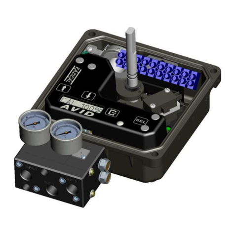
Avid Technology SMARTCAL User manual

CRANECO.
280N.MIDLANDAVE.,STE258,SADDLEBROOK,NJ07663WWW.AVIDCONTROLS.COM
12/17/12 TECH-440/D.W.O. 23135 Page 1 of 55
SMARTCAL
VALVE POSITIONER
INSTALLATION AND OPERATION MANUAL
IOM: Tech-440 Revision: A
Prepared By:
M. Twardowski
Date:
12/17/12
Drafting Work Order:
23135
ECN:
13247
Reviewed By: C. Irwin Date: 3/14/18 Approved By: T. Paolini Date:10/18/18
This IOM contains confidential information and is issued in confidence on the condition that it be returned on demand and not be copied,
reproduced, disclosed to others or used in manufacture of the subject matter thereof without the written consent of Crane Co.

CRANECO.
280N.MIDLANDAVE.,STE258,SADDLEBROOK,NJ07663WWW.AVIDCONTROLS.COM
12/17/12 TECH-440/D.W.O. 23135 Page 2 of 55
Revision History
Revision
Sept 3, 2014
Initial release
October 24, 2017
Revision A
Crane Co.
Americas: +1 201 794 7650
Europe, Middle East & Africa: +44 (0) 1892 516 277
Asia Pacific: +65 6869 8909

CRANECO.
280N.MIDLANDAVE.,STE258,SADDLEBROOK,NJ07663WWW.AVIDCONTROLS.COM
12/17/12 TECH-440/D.W.O. 23135 Page 3 of 55
Table of Contents
1.Introduction..................................................................................5
1.1ProductCertification.....................................................................................................................5
1.2DescriptionofSmartCalPositioner...............................................................................................5
1.3PrincipleofOperation...................................................................................................................6
1.4SpecialFeatures............................................................................................................................7
2Ordering........................................................................................9
2.1SmartCalPositionerOrderingGuide.............................................................................................9
3InitialSetup.................................................................................10
3.1MountingPositioneronaRotaryActuator.................................................................................10
3.2MountingRemotePositioneronaRotaryActuator...................................................................12
3.3MountingPositioneronaLinearActuator.................................................................................13
3.4MountingRemotePositioneronaLinearActuator(Models5215&5315)...............................15
3.5PneumaticConnection................................................................................................................18
3.6ElectricalConnection..................................................................................................................19
4Calibration..................................................................................21
4.1EnterCalibration(MenuLevel)...................................................................................................21
4.2AutomaticCalibration.................................................................................................................22
4.3ProceedtoExitingCalibrationorPerformAdvancedCalibration..............................................23
4.4ExitingCalibration.......................................................................................................................24
4.5ConfigurethePositionersParameters........................................................................................24
4.6ManualOverrideofInputSignal(ViaOn‐BoardKeypad)...........................................................25
4.7DescriptionofMenus..................................................................................................................25
4.8DescriptionofFunctions.............................................................................................................26
5TroubleShooting.........................................................................30
5.1PreliminaryChecks.....................................................................................................................30
5.2FAQ’s...........................................................................................................................................31
6TechnicalSpecifications..............................................................33
7ErrorcodesandLCDmessages....................................................34
7.1ErrorcodesthatarebackwardcompatibletopreviousversionsoftheSmartCalpositioner....34
7.2LCDerrormessages.....................................................................................................................35
Appendix A.........................................................................................................................40
ProceduretoAdjusttheError3Setting(orLowinputpressure)...........................................................40
Appendix B.........................................................................................................................41
ProceduretoRemoveElectronicsCoverandElectronicCanister..........................................................41
Appendix C.........................................................................................................................42
SettingtheTransmitterOutputFailcurrent...........................................................................................42
Appendix D.........................................................................................................................43
ProceduretoCheckTransducerOperation............................................................................................43
Appendix E.........................................................................................................................44
GeneralMaintenanceStandardFlow.....................................................................................................44

CRANECO.
280N.MIDLANDAVE.,STE258,SADDLEBROOK,NJ07663WWW.AVIDCONTROLS.COM
12/17/12 TECH-440/D.W.O. 23135 Page 4 of 55
Appendix F.........................................................................................................................46
GroundingSchematic..............................................................................................................................46
Appendix G.........................................................................................................................47
ControlSchematicforWiringofIntrinsicallysafeSmartCalforATEX&IECEX.......................................47
Appendix H.........................................................................................................................49
ControlSchematicforWiringofIntrinsicallysafeSmartCal(WD‐10836)forUS&CANADA.................49
Appendix I...........................................................................................................................53
ProceduretoResettheNon‐VolatileMemorytoFactorySettings........................................................53
Appendix J..........................................................................................................................54
HART®CommunicatorMenuFlowChart.................................................................................................54
Appendix K.........................................................................................................................54
DDandDTMforconfigurationandcontrolsystemintegration.............................................................55

CRANECO.
280N.MIDLANDAVE.,STE258,SADDLEBROOK,NJ07663WWW.AVIDCONTROLS.COM
12/17/12 TECH-440/D.W.O. 23135 Page 5 of 55
1. Introduction
1.1 Product Certification.
IEC Ex FMG 06.0002x
Ex ia IIC T4
II 1 G
Ex ia IIC T4
II 1G
FM09 ATEX 0028
II3 DT 75~C
nnnn
Ex ia IIC T4
CLASS I DIV 1 GROUP A, B, C, D
CLASS II DIV 1 GROUP E, F, G
NI CLASS I DIV 2 GROUP A, B, C, D
This product is designed for use in intrinsically safe systems when connected
through the correct barriers.
1.2 Description of SmartCal Positioner.
The SmartCal Smart Valve Positioner is an electro-
pneumatic servo system that continuously controls
the position of a valve based on a 4 to 20 mA input
signal. The SmartCal is an instrument that derives its
power directly from a control systems current loop.
The instrument senses valve position via a non-
contact Hall Effect sensor and controls valve position
through a current to pressure transducer.
The SmartCal is available in two versions, HART®
and non-HART. The non-HART version allows
calibration of the instrument through an on board
keypad. The HART® version allows calibration and
access to on-line diagnostic information via
Rosemount 375/475 hand-held terminal or through
software.
The positioner has a local liquid crystal display which
indicates valve position and set-point in percentage
of full span. It also indicates whether the positioner
is in calibration mode.
The SmartCal has the capability to monitor operation. If a failure condition occurs,
an error message is displayed on the local liquid crystal display.
There are several accessories that can be integrally supplied with the SmartCal.
Among these are a 4 to 20 mA analog output, and a set of hermetically sealed non-
contact limit switches.

CRANECO.
280N.MIDLANDAVE.,STE258,SADDLEBROOK,NJ07663WWW.AVIDCONTROLS.COM
12/17/12 TECH-440/D.W.O. 23135 Page 6 of 55
1.3 Principle of Operation
Unlike conventional positioners, the SmartCal Smart Positioner feeds back
valve position without the need for linkages, levers, or rotary and linear seals.
Position sensing is performed totally by non-contacting means, permitting use
of advanced control strategies where knowledge of valve position is used in
predictive and other algorithms. By the integration of multiple components into
a singular, cost efficient unit, microprocessor-based intelligence can now be
used to implement advanced functions such as early warning diagnostics.
The SmartCal positioner provides intelligence for the control valve through a
microprocessor-based diagnostic system utilizing HART®or Foundation
Fieldbus protocols. Accurate measurement of valve stem position, input signal,
actuator pressure and travel time can be recorded during normal operation,
thereby providing information for control valve signature generation.
Housing Material:
Engineered Resin
Housing Material:
316 Stainless Steel
or Aluminum

CRANECO.
280N.MIDLANDAVE.,STE258,SADDLEBROOK,NJ07663WWW.AVIDCONTROLS.COM
12/17/12 TECH-440/D.W.O. 23135 Page 7 of 55
1.4 Special Features
Non-Contact Position Feedback
To provide consistently accurate performance information, all linkages, levers
and connecting rods, from the positioner to the control valve have been
eliminated from the design. Valve position sensing is performed totally by non-
contact means based upon characterization of magnetic flux strength as a
function of position.

CRANECO.
280N.MIDLANDAVE.,STE258,SADDLEBROOK,NJ07663WWW.AVIDCONTROLS.COM
12/17/12 TECH-440/D.W.O. 23135 Page 8 of 55
Remote Position Control
Since valve position feedback to the SmartCal positioner
is accomplished by non-contact means, the SmartCal has
the unique ability to be mounted remotely (up to a distance
of 50 feet, optionally 150 feet) from the device it is
controlling. The remote position sensor also has the ability
to work over a wider temperature range, from -40C to
125C (-40F to 257F). In the event the control valve is
located in a high vibration, high temperature or extremely
corrosive environment, the non-contact position feedback
feature allows for isolated placement of the positioner.
Local Graphic LCD
The SmartCal positioner is supplied with a digital
communication interface (FF, HART
®
) or a 3-button keypad interface. Both versions are furnished
with a graphic LCD, and allow for automated calibration of the
positioner. The local LCD provides a multitude of onsite diagnostic
information. The LCD shows input current, set-point and current
position. The values displayed range from 0.0% to 100.0%. Displayed
resolution is in 0.1% increments, however, internal calculations are
maintained at higher precision.
On-Board Sensors
The SmartCal positioner has the capability to monitor its operation. If an error or failure condition
occurs, it will be displayed on the local LCD, or if the positioner is supplied with a HART
®
interface,
the error codes will be displayed on a hand held terminal or a PC maintenance station. Note: Error
codes are denoted on a label affixed to the LCD flip-up protective cover.
Local Keypad
The positioner is provided with a ruggedized 3-button keypad. The keypad can be
used for zero and span adjustments, as well as valve characterization and gain
adjustments.
Intelligent Calibration (HART
®
Protocol)
The SmartCal positioner responds to HART
®
commands for seeking the “valve
closed” position and assigns an instrument signal of 4 mA to this position. The
counterpart of the operation for a full open state is implemented next by setting the span value.
Action reversal is also configured. Additionally, provisions are made for altering internal servo
loop tuning via the HART
®
link. In this manner, positioner performance may be optimized with a
wide combination of valves and actuators.
Negligible Bleed
Designed to consume the least possible amount of control air at steady state, the SmartCal
positioner can greatly reduce the air consumption of your process and reduce the demand on
instrument air compressors. To increase reliability, the SmartCal employs a patented lapped spool
and floating sleeve design. This balanced construction relies on an air bearing which eliminates
any metal to metal contact.
A
VID
SmartCal HART Rev 1.01.06
25.5°C
R %PS 50.0 %SP 50.0
12.0 mA OK

CRANECO.
280N.MIDLANDAVE.,STE258,SADDLEBROOK,NJ07663WWW.AVIDCONTROLS.COM
12/17/12 TECH-440/D.W.O. 23135 Page 9 of 55
2 Ordering
The SmartCal positioner is designed to handle a wide range of control valve applications. Please use the
following ordering guide to help choose the SmartCal positioner that best suits the application.
2.1 SmartCal Positioner Ordering Guide

CRANECO.
280N.MIDLANDAVE.,STE258,SADDLEBROOK,NJ07663WWW.AVIDCONTROLS.COM
12/17/12 TECH-440/D.W.O. 23135 Page 10 of 55
3 Initial Setup
3.1 Mounting Positioner on a Rotary Actuator
Step 1. Figure 1 shows typical direct mounting of positioner to an actuator. Mount the
modmount bracket to positioner using positioner mounting screws.
Figure 3-1

CRANECO.
280N.MIDLANDAVE.,STE258,SADDLEBROOK,NJ07663WWW.AVIDCONTROLS.COM
12/17/12 TECH-440/D.W.O. 23135 Page 11 of 55
Step 2. The visual indicator needs to be properly oriented. Use the symbols on the bottom
of the indicator to mount as shown in Condition 1 or Condition 2. (see figure 3-2).
Condition 1 and Condition 2
show the placement of the indicator with respect to the positioner housing while the
actuator is in the fail position.
Step 3. Mount the positioner with Modmount bracket to the actuator. As stated in Step 2
make sure that the positioner is mounted in a fashion that properly orients it with respect
to the indicator.
Figure 3-2

CRANECO.
280N.MIDLANDAVE.,STE258,SADDLEBROOK,NJ07663WWW.AVIDCONTROLS.COM
12/17/12 TECH-440/D.W.O. 23135 Page 12 of 55
3.2 Mounting Remote Positioner on a Rotary Actuator
Step 1. Mount bracket and visual indicator to positioner as described in Section 3.1 Step
1.
Step 2. The visual indicator needs to be properly oriented. Use the symbols on the bottom
of the indicator to mount as shown in Condition 1 or Condition 2. (see figure 3-3).
Condition 1 and Condition 2 show the placement of the indicator with respect to the
positioner housing while the actuator is in the fail position.
Step 3. Mount the positioner with Modmount bracket to the actuator. As stated in Step 2
make sure that the position sensor is mounted in a fashion that properly orients it with
respect to the indicator.
Figure 3-3

CRANECO.
280N.MIDLANDAVE.,STE258,SADDLEBROOK,NJ07663WWW.AVIDCONTROLS.COM
12/17/12 TECH-440/D.W.O. 23135 Page 13 of 55
Step 4. Mount positioner at a remote location.
Step 5. Remove the electronic canister cover by unscrewing (2) mounting screws.
(Appendix B: Procedure to Remove Electronics Cover and Electronic Canister)
Step 6. If necessary cut remote cable to required length, making sure to cut end opposite
female connector. Wire the positioner sensor back to the positioner using the cable
provided and replace cover. (See Figure 3-4).
Figure 3-4

CRANECO.
280N.MIDLANDAVE.,STE258,SADDLEBROOK,NJ07663WWW.AVIDCONTROLS.COM
12/17/12 TECH-440/D.W.O. 23135 Page 14 of 55
3.3 Mounting Positioner on a Linear Actuator
Step 1. Mount the magnet assembly to the stem of the actuator. A coupler block normally
is needed to extend the magnet assembly outside the yoke area and into the sensing
range of the magnetic pick-up unit.
Step 2. Fasten the mounting bracket to the actuator.
Step 3. Mount the positioner to the mounting bracket. The positioner should be mounted
so the magnetic pick-up unit of the positioner is centered between the limits of the
magnetic assembly’s stroke. After mounting the positioner, the magnet assembly should
be within 1/8” [3.2 mm] from the back of the positioner (1/16” [1.6 mm] is ideal), (See
Figure 3-5)
Figure 3-5
Note: For Fisher actuators model 657 & 667 sizes 34 thru 70, a slotted mounting kit
design can be supplied. This will allow the user to easily center the positioner sensor
between the limits of the magnet assembly’s stroke. Other mounting kits are available
upon request.

CRANECO.
280N.MIDLANDAVE.,STE258,SADDLEBROOK,NJ07663WWW.AVIDCONTROLS.COM
12/17/12 TECH-440/D.W.O. 23135 Page 15 of 55
Figure 3-6
To Center the Positioner
1. Stroke the actuator to its upper limit and place a mark on the actuator’s yoke that
lines up with the red arrow on the magnet assembly.
2. Stroke the actuator to its lower limit and place a mark on the actuator’s yoke that
lines up with the red arrow on the magnet assembly.
3. Place a third mark on the yoke centered between the upper and lower limit marks.
4. Lastly, mount the positioner to the bracket so that the positioner sensor (nose) of
the SmartCal lines up with the midpoint mark. (See Figure 3-6).
3.4 Mounting Remote Positioner on a Linear Actuator
SmartCal

CRANECO.
280N.MIDLANDAVE.,STE258,SADDLEBROOK,NJ07663WWW.AVIDCONTROLS.COM
12/17/12 TECH-440/D.W.O. 23135 Page 16 of 55
Step 1. Mount the magnet assembly and bracket to the actuator as described in Section
3.3 Step 1.
Step 2. Mount the position sensor housing so that the conduit entry faces away from the
diaphragm or cylinder. (See Figure 3-7)
Figure 3-7
Note: For Fisher actuators model 657 & 667 sizes 34 thru 70, a slotted mounting kit
design can be supplied to ease the mounting process. This will allow the user to easily
center the positioner sensor between the limits of the magnet assembly’s stroke. Other
mounting kits are available upon request
Step 3. Mount positioner at a remote location,

CRANECO.
280N.MIDLANDAVE.,STE258,SADDLEBROOK,NJ07663WWW.AVIDCONTROLS.COM
12/17/12 TECH-440/D.W.O. 23135 Page 17 of 55
Step 4. Remove the electronic canister cover by unscrewing (2) mounting screws.
(Appendix B: Procedure to Remove Electronics Cover and Electronic Canister)
Step 5. If necessary cut remote cable to required length, making sure to cut end opposite
female connector. Wire the positioner sensor back to the positioner using the cable
provided and replace cover. (See Figure 3-8).
Figure 3-8

CRANECO.
280N.MIDLANDAVE.,STE258,SADDLEBROOK,NJ07663WWW.AVIDCONTROLS.COM
12/17/12 TECH-440/D.W.O. 23135 Page 18 of 55
3.5 Pneumatic Connection
Single Acting Actuator (Spring Return):
For single acting actuators Outlet Port 2 is to be plugged. Outlet Port 1 is to be piped to
the actuator inlet port that acts against the spring. (increasing set-point signal causes
pressure to increase in Outlet Port 1 of the positioner).
Double Acting Actuator (Double Return):
For double acting actuators Outlet Port 2 is piped to drive the actuator towards the fail
position. Outlet Port 1 is piped to drive the actuator away from the fail position. (increasing
set-point signal causes pressure to increase in Outlet Port 1 of the positioner and pressure
to decrease in Outlet Port 2 of the positioner).
Note: Air supply to the positioner must be clean, dry, oil free instrument air per ISA-S7.3.
Maximum supply pressure is 120 psi. All pneumatic connections are 1/4” NPT or 1/4 BSP.
1. Single Acting/Spring Return (Plug Outlet Port 2) increasing signal causes pressure to
increase in Outlet Port 1.
2. Double Acting/Double Return (Pipe Outlet Port 2 to drive actuator towards the
desired failure direction) increasing signal causes pressure to decrease in Outlet Port
2 and pressure to increase in Outlet Port 1.
Notes:
1. On loss of electrical power Outlet Port 1 has zero pressure and Outlet Port 2 has full
pressure.
Figure 3-9

CRANECO.
280N.MIDLANDAVE.,STE258,SADDLEBROOK,NJ07663WWW.AVIDCONTROLS.COM
12/17/12 TECH-440/D.W.O. 23135 Page 19 of 55
3.6 Electrical Connection
A) The certification applies to equipment without cable glands. When mounting the
enclosure in the hazardous areas, only suitably certified cable glands and blanking
elements must be used to maintain ingress protection of IP66.
B) All unused cable entries must be plugged with suitably certified plugs that can
maintain an ingress protection level of IP66.
C) The positioner, switches, sensors and coils shall be electrically connected suitable
to the rated data via a certified isolating interface/zener barrier placed outside the
hazardous areas.
D) For ambient temperatures below -10~C and above +60~C, use field wiring suitable
for both minimum and maximum ambient temperatures.
E) Electromagnetic compatibility (emissions and susceptibility) is guaranteed only if
the unit and all cables are shielded and grounded as illustrated in Appendix F.
1. Remove positioner cover.
2. Locate terminal strip and carefully disconnect (slide
off).
3. Connect the 4 to 20 mA loop signal to terminal points
marked (+) and (-). See figure 3-10 for a wiring
schematic.
4. If the positioner was ordered with an analog output,
connect output wiring to terminal points 5 & 6,
(polarities shown on figure 3-10). The 4-20mA analog
output is of the current sink type therefore it requires
a suitable external DC power supply (24VDC
nominal).
5. If the positioner was ordered with switches, connect to the switches at terminal points
1 thru 4, as shown in Figure 3-10.
6. After all connections have been made reconnect the terminal strip and replace
positioner cover.

CRANECO.
280N.MIDLANDAVE.,STE258,SADDLEBROOK,NJ07663WWW.AVIDCONTROLS.COM
12/17/12 TECH-440/D.W.O. 23135 Page 20 of 55
Figure3-10
Table of contents
Other Avid Technology Valve Positioner manuals
Popular Valve Positioner manuals by other brands

Samson
Samson TROVIS SAFE 3731-3 Mounting and operating instructions

VAC
VAC V200 POSITIONER Installation,operation and maintenance instruction

PI
PI PIMAG V-417.6025E0 Series user manual

Baileigh
Baileigh WP-1100 Operator's manual

Siemens
Siemens SIPART PS2 Hardware installation manual

Siemens
Siemens SIPART PS2 operating instructions

Siemens
Siemens SIPART PS2 6DR5 series Compact operating instructions

Samson
Samson 3730 Series Mounting and operating instructions

Aerotech
Aerotech ABL1000 Hardware manual

Heinzmann
Heinzmann PANDAROS DC 6-06 manual

Flowserve
Flowserve D20 Series Installation operation & maintenance

PI
PI PIMAG V-412.xx6025E0 Series user manual