Genebre 5950 00 User manual

Genebre Building. Av. de Joan Carles I, 46-48
08908 L'Hospitalet de Llobregat. Barcelona (Spain)
genebre@genebre.es - www.genebre.es
GENEBRE S.A.
UPDATE DATE: 07/07/2020 UPDATE NUMBER: 1
1
INSTALLATION, OPERATION AND
MAINTENANCE MANUAL
Pneumatic Positioner for Rotary
Actuators
GENEBRE Reference: 5950 00

Genebre Building. Av. de Joan Carles I, 46-48
08908 L'Hospitalet de Llobregat. Barcelona (Spain)
genebre@genebre.es - www.genebre.es
GENEBRE S.A.
UPDATE DATE: 07/07/2020 UPDATE NUMBER: 1
2
INSTALLATION, OPERATION AND MAINTENANCE INSTRUCTIONS
1. Product Description........................................................................................................3
2. Data and Technical Features.........................................................................................3
3. Security Instructions.......................................................................................................3
4. Transport and Storage Conditions.................................................................................4
5. Preliminary Checks........................................................................................................4
6. Positioner Installation.....................................................................................................5
6.1 Installation of the Support and the Positioner on the actuator..................................5
6.2 Mounting of the Cam................................................................................................5
6.3 Air Connection..........................................................................................................6
7. Exploded view................................................................................................................7
8. Starting Up (Settings).....................................................................................................8
8.1 Zero Setting..............................................................................................................8
8.2 Span Setting.............................................................................................................8
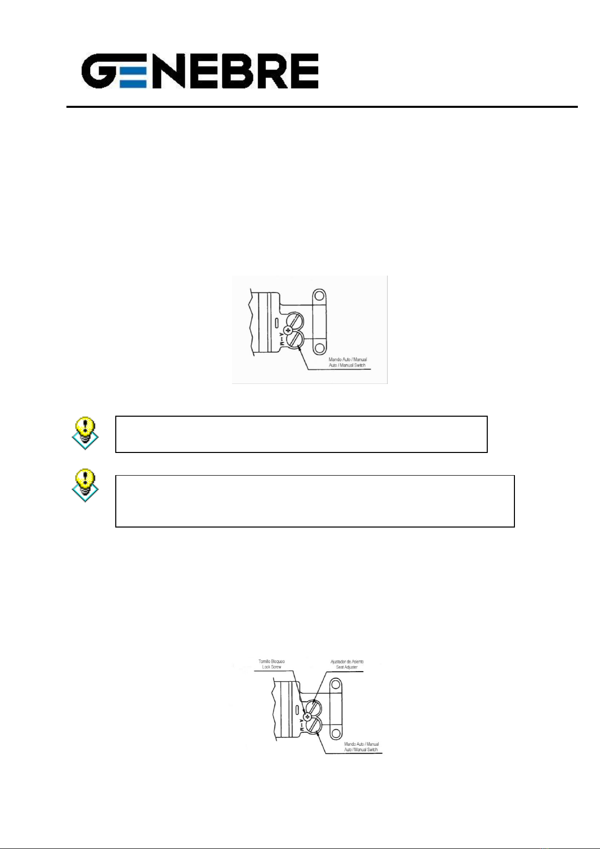
8.3 Auto / Manual Switch................................................................................................9
8.4 Seat Adjustment.......................................................................................................9
8.5 Air throttle in pilot valve ..........................................................................................10
9. Maintenance................................................................................................................10
10. Cleaning the A / M Switch..........................................................................................11
11. Safety Instructions ………………………………………………………………………... 11

Genebre Building. Av. de Joan Carles I, 46-48
08908 L'Hospitalet de Llobregat. Barcelona (Spain)
genebre@genebre.es - www.genebre.es
GENEBRE S.A.
UPDATE DATE: 07/07/2020 UPDATE NUMBER: 1
3
1. Product Description.
The pneumatic positioner is used for rotating operation of valves with pneumatic
actuators by means of air pressure, with a signal range of 3 to 15 PSI (0,2 to 1 bar).
It can be used with double effect or single effect actuators. Easy setting of zero and of the
trajectory. Easy switching of direction (clockwise / counter-clockwise).
Low air consumption and easy connection to air ducts.
2. Data and Technical Features
Description
Values
Input signal
3 ~ 15 psi (0,2 ~ 1 bar)
Supply pressure
1.4 ~ 7 bar (20 ~ 100psi)
Stroke
0 - 90°
Air connection
G 1/4”
Gauge connection
G 1/8”
Protection
IP66
Ambient temperature
-20°C ~ 70°C
Linearity
± 1,5 % F.S. (Full Scale)
Hysteresis
± 1,5 % F.S. (Full Scale)
Sensitivity
± 0.4 % F.S. (Full Scale)
Air consumption
3 LPM (Sup = 1.4 bar, 20psi)
Flow capacity
80 LPM (Sup =1.4 bar, 20psi)
Material
Aluminum Alloy
Weight
2,7 Kg.
3. Security Instructions
The goal of this manual is to allow users with technical skills to install, turn on, operate
and inspect Genebre’s electro-pneumatic positioners. Qualified personnel must be
familiar with all notices and warnings described in these instructions. Not complying with
these notices and warnings may cause serious personal injury and material damages.

Genebre Building. Av. de Joan Carles I, 46-48
08908 L'Hospitalet de Llobregat. Barcelona (Spain)
genebre@genebre.es - www.genebre.es
GENEBRE S.A.
UPDATE DATE: 07/07/2020 UPDATE NUMBER: 1
4
4. Transport and Storage Conditions
•The positioners are shipped from the Genebre, S.A. headquarters in
appropriate packaging to prevent damage.
•Any slings, ropes or chains used to lift or transport motorized valves must NOT
be attached to the positioner under any circumstances.
•The positioner’s supports are designed to withstand the action efforts but NOT
the total weight of the valve, or any other type of burden or effort.
•Do NOT bang the positioner against walls, floors or other machines. That could
cause severe damage to the positioner or its parts.
•Store in a dry and well-ventilated place, safe from bad weather conditions.
Avoid placing them straight on the floor. Use pallets, shelves o wood bases.
•Genebre, S.A. recommends to visually examine the possible damages suffered
during transportation and storage. Visual inspection must include the interior of
compartments.
5. Preliminary Checks
•Verify that the characteristics of the positioner match those required before
proceeding to install and turn on the device. That data can be found in the data
plate.
•Should there be any deviation or non-conformance, please contact Genebre, S.A.
Certain parts of the positioner are subject to mechanical movement
which may cause injury.
Work on the system or electric equipment must only be performed by
qualified technicians or by trained personnel under the control and
monitoring of said technicians, according to the security rules and
guidelines, as well as other applicable national laws.
Negligent use may cause serious damage to the parts, installation and
people, as well as to the equipment itself. Under no circumstance can
any part or component of the positioner be modified or altered. Such
alterations or modifications automatically invalidate the designed use
of the positioner.

Genebre Building. Av. de Joan Carles I, 46-48
08908 L'Hospitalet de Llobregat. Barcelona (Spain)
genebre@genebre.es - www.genebre.es
GENEBRE S.A.
UPDATE DATE: 07/07/2020 UPDATE NUMBER: 1
5
•Maximum pressure of air supply 7 bar (100 PSI)
6. Positioner Installation
6.1 Installation of the Support and the Positioner on the actuator
•Connection to the fixing of the output shaft in which the position of the
positioner’s output shaft and the main shaft of the rotating actuator are
concentric. Type C connection (see figure) is Namur, direct connection to the
actuator.
•The positioner’s support is designed to be mounted on actuators with a shaft
height of H=20 or H=30, as well as fixing holes at 80 mm or 130 mm according
to Namur regulations.
6.2 Mounting of the Cam
Attention: Do not supply air to the equipment during this operation. It
may be highly dangerous.
Make sure the supply air to be used is Dry, Clean and Filtered, since
bad quality supply air may seriously damage the positioner.

Genebre Building. Av. de Joan Carles I, 46-48
08908 L'Hospitalet de Llobregat. Barcelona (Spain)
genebre@genebre.es - www.genebre.es
GENEBRE S.A.
UPDATE DATE: 07/07/2020 UPDATE NUMBER: 1
6
Note: The positioner leaves the factory with the cam mounted on the shaft and the
indicator plate in the position “RA” (counter-clockwise/reverse acting).
In case you need to switch the direction (clockwise/direct acting) proceed as follows:
•Lift the cover of the positioner.
•Remove the clamping screw from the indicator plate and remove the plate.
•Remove the clamping nut from the cam.
•Remove the cam and turn with the side marked as “DA” facing up.
•Mount the cam on the ledge of the output shaft.
•Set the actuator on the initial position.
•Fix the cam using the upper nut so that the reference line “0” is tangent to the
bearing.
•Once the cam is mounted, place and fix the indicator plate to the main shaft using
the M3 screw so that the reference lines for the cam and the indicator match up.
6.3 Air Connection.
Attention: Make sure the supply air to be used is Dry, Clean and
Filtered.

Genebre Building. Av. de Joan Carles I, 46-48
08908 L'Hospitalet de Llobregat. Barcelona (Spain)
genebre@genebre.es - www.genebre.es
GENEBRE S.A.
UPDATE DATE: 07/07/2020 UPDATE NUMBER: 1
7
1. Use a regulator with a filter to constantly maintain the supply air pressure
(optimum supply pressure of 6 bar to operate the actuator).
2. Purge the air circuit completely to avoid strange particles.
3. In applications with single effect actuator (spring return) close output OUT1 or
OUT2 as appropriate.
7. Breakdown view
Cover
Span Unit
Connector
Bellows mechanism
Zero Unit
Base
Pilot Valve
Cam
Shaft

Genebre Building. Av. de Joan Carles I, 46-48
08908 L'Hospitalet de Llobregat. Barcelona (Spain)
genebre@genebre.es - www.genebre.es
GENEBRE S.A.
UPDATE DATE: 07/07/2020 UPDATE NUMBER: 1
8
8. Starting Up (Settings)
Note: The positioner leaves the factory set to position 0º and path 90º. In case you
need to establish these settings, proceed as follows.
8.1 Zero Setting
•Send a run start signal (3 PSI).
•Turn the ZERO setting wheel clockwise or counter-clockwise until the reference
lines of the indicator cam and the tangent point of the bearing match.
ZERO
•In the case of the single effect actuator, check that it is set to zero point at
standard pressure. Otherwise, repeat Zero Setting.
8.2 Span Setting
•Set the span so that the actuator stops at position 0% in the run with an input
signal of 0% (3 PSI), and so that it stops at position 100% with an input signal of
100% (15 PSI), respectively.
•Check Zero point and repeat the Span setting as many times as required.
•Once the equipment is set, tighten the Locking screw.

Genebre Building. Av. de Joan Carles I, 46-48
08908 L'Hospitalet de Llobregat. Barcelona (Spain)
genebre@genebre.es - www.genebre.es
GENEBRE S.A.
UPDATE DATE: 07/07/2020 UPDATE NUMBER: 1
9
8.3 Auto / Manual Switch
This switch is used to switch between Auto and Manual modes. The equipment leaves
the factory in Auto mode. To switch to Manual mode, turn the A/M regulator counter-
clockwise.
In Manual mode, the network pressure connects directly to the actuator. Return to Auto
mode after using.
This option does not apply to the single effect actuator connected to output OUT2.
8.4 Seat Adjustment
•In case of very low sensitivity due to the actuator working at its maximum load
limit, turn the Seat Adjuster clockwise. If the equipment keeps oscillating, turn
counter-clockwise until balance is achieved. Be careful not to loosen the Lock
Screw since it might come off the Seat Adjuster.
•In case of oscillation due to mounting with a low air capacity actuator, refer to
section 8.5.
Attention: This adjustment is done in the factory so it is not
necessary to readjust later.
ATTENTION! This adjustment must only be performed by qualified
technicians. Otherwise the equipment might completely lose its
configuration.

Genebre Building. Av. de Joan Carles I, 46-48
08908 L'Hospitalet de Llobregat. Barcelona (Spain)
genebre@genebre.es - www.genebre.es
GENEBRE S.A.
UPDATE DATE: 07/07/2020 UPDATE NUMBER: 1
10
8.5 Air throttle in pilot valve
In case of low air capacity actuators, there could be oscillation in the equipment,
rendering it inoperative. In such a case, use air throttles in outputs OUT1 and OUT2 of
the pilot valve. There are two available measures that come with the equipment:
Actuator Volume
Output Orifice Diameter
Smaller than 90 cm3
Ø 0,7
Between 90 ~ 180 cm3
Ø 1,0
Bigger than 180 cm3
None
•Remove the pilot valve.
•Remove the o-ring, place the throttle and insert the o-ring again. Be careful not to
leave any foreign bodies in the orifice of the throttle.
•Perform the same operation on both air outputs (OUT 1 and OUT 2).
•Replace the pilot valve.
If the oscillation persists after performing this operation, please contact Genebre S.A.
9. Maintenance
Even though this equipment requires no maintenance, it is recommended to carry out
regular inspections, which must include:
•Verifying the mounting / alignment of the actuator and the positioner.
•Verifying the electrical connection of the signal.
•Making sure all bolts are present and tightened.
•Verifying the state of the filters of the air installation to ensure that good quality air
reaches the equipment.

Genebre Building. Av. de Joan Carles I, 46-48
08908 L'Hospitalet de Llobregat. Barcelona (Spain)
genebre@genebre.es - www.genebre.es
GENEBRE S.A.
UPDATE DATE: 07/07/2020 UPDATE NUMBER: 1
11
10. Cleaning the A / M Switch
Whenever the positioner does not respond correctly to the input signals, proceed as
described below:
•Turn off any air or power supply.
•Remove the A/M Switch regulator from the pilot valve.
•Insert the wire (included in the inner part of the cover) through the air flow hole
located on the A/M regulator to remove any particles that might be left inside.
Cleaning the A/M Switch
•Finally, clean the A/M Switch regulator using air and place it back in the enclosure.
Do not forget to use the Lock Screw.
•The equipment is ready for operation.
Note: In the event that the positioner does not respond, proceed to change the pilot valve
(Ref.P5951).
11. Safety Instructions
When operating any kind of element, you must follow the security instructions and it is
recommended to use personal protection gadgets:
1) Protect your eyes.
2) Wear gloves and appropriate working clothes.
3) Wear safety footwear.
4) Wear a helmet.
5) Have running water at hand.
Table of contents
Other Genebre Valve Positioner manuals
Popular Valve Positioner manuals by other brands

rotork
rotork YT-1200 Series product manual

SMAR
SMAR FY400 Owner's operation and maintenance manual

Peaktronics
Peaktronics 92 Series Installation, operation and maintenance manual

Samson
Samson TROVIS 3730-3 Mounting and operating instructions

ABB
ABB VAC D500 Commissioning instructions

Azbil
Azbil AVP300 user manual