Avidsen BambooView User manual

www.avidsen.com
V8
Eco
Friendly
Made with
&
YEARS
3
THE ECO-FRIENDLY
VIDEOPHONE
BambooView
Ref.112282 - Ref.112283
Designed to last
Compatible with any home
Easy to install and use
EN

EN3
EN 2
TABLE
OF CONTENTS
A -SAFETY
INSTRUCTIONS 05
1 - INTRODUCTION 05
2 - MAINTENANCE AND CLEANING 05
3 - RECYCLING 05
B - PRODUCT
DESCRIPTION 06
1 -KIT CONTENTS 06
2 - MONITOR 06
3 - INTERCOM PANEL 07
4 - WALL BRACKET 07
5 - MAINS ADAPTOR 07
C - INSTALLATION 08
1 - INSTALLATION OF THE INTERCOM PANEL 08
2 - INSTALLING THE MONITOR 10
3 - CONNECTIONS 10
3.1 - Connection between the monitor and the
intercom panel 11
3.2 - Connections 12
3.2.1 - Connections 2 monitors + 2 intercom
panels 12
3.2.2 - Connections 2 monitors
+ 1 Camera 12
3.2.3 - Settings for 2 families 13
3.2.4 - Connection to an electric strike plate with
additional power supply 13
3.3 - Activation and use of badges 14
3.3.1 - Initialisation 14
3.3.2 - Adding user badges 16
3.3.3 - Deactivating all badges 16
3.3.4 - Selecting the action associated with the
user badges 16
D - USING THE
PRODUCT 17
1 - IDENTIFY AND SPEAK TO THE VISITOR 17
2 - ACTIVATE THE INTERCOM PANEL FROM THE
MONITOR 17
3 - OPENING AN ELECTRIC LOCK AND AN
AUTOMATIC CONTROL SYSTEM (OPTIONAL) 17
4 - INTERCOM FEATURE 17
5 - MONITOR SETTINGS 18
6 - UNLOCKING USING A BADGE 18
7 - CHECKING PHOTOS TAKEN IN YOUR
ABSENCE 18

EN3
EN 2
TABLE
OF CONTENTS
E - TECHNICAL
AND LEGAL
INFORMATION 19
1 -TECHNICAL CHARACTERISTICS 19
2 - WARRANTY 20
3 -HELP AND ADVICE 20
4 - PRODUCT RETURNS/
AFTER SALES SERVICE 20
5 - DECLARATION OF CONFORMITY 20

EN 4

EN5
A - SAFETY INSTRUCTIONS
1 - INTRODUCTION
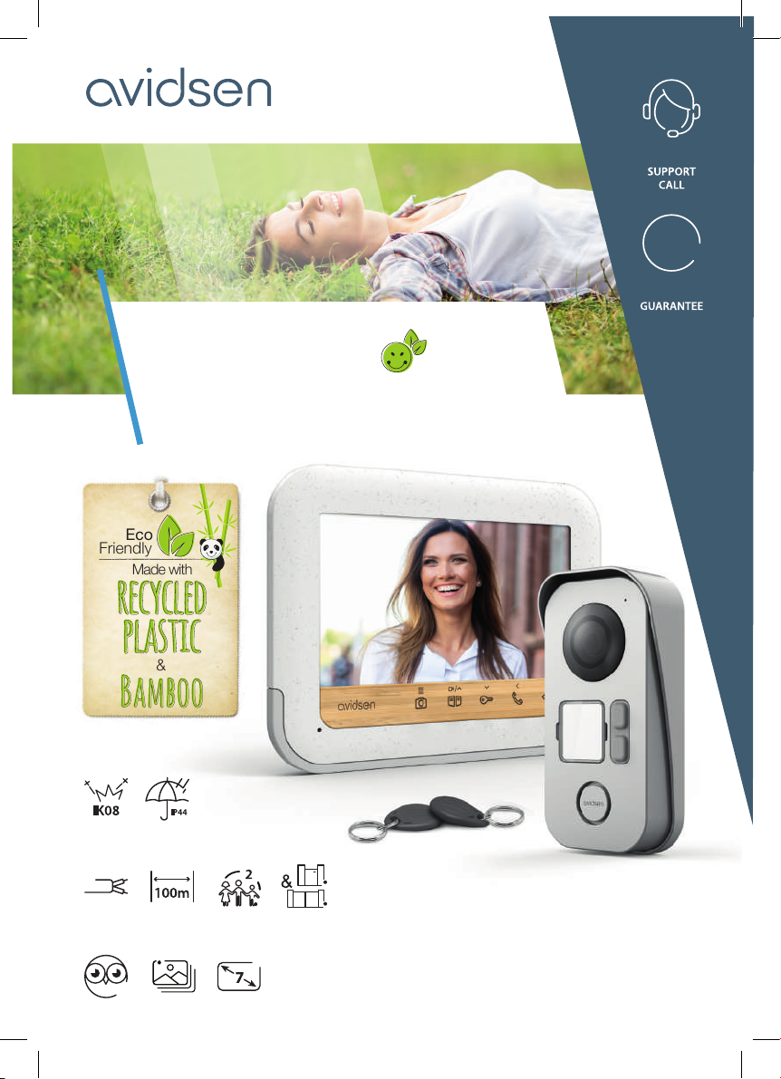
This video intercom system pairs two modules: a
receiver-monitor and an easy-to-install and use
intercom panel.
Key features:
• Colour video reception: when a visitor touches the
intercom panel call button, the panel immediately
transmits the image to the screen and a chime
indicates the visitor’s presence.
• Short-circuit protection
• Reverse polarity protection
• Automatic exposure correction: the video camera
automatically adjusts its exposure to match the
ambient light conditions.
• Enables control over two entrances (lock and
automated entryway).
• Integrated infrared vision enables the video
camera to identify visitors without needing
additional light.
• Opening the door and a control system: by
pressing buttons on the monitor, you can
control an electric lock and a dry contact for an
automated entryway (not included).
• Opening an electric strike plate or automated
entryway (not included) when one of the two
provided user badges is shown.
IMPORTANT: This notice should be read carefully
prior to installation. In the case of any problems,
our Hotline technicians are at your service to
provide you with any information you may need.
WARNING: any connection error may cause
damage to the device and void the warranty.
2 - MAINTENANCE AND INSTALLATION
GUIDANCE
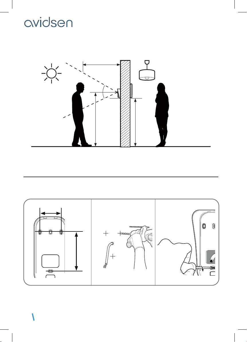
Before installing the intercom, it is important to
check the following points:
• Do not install in cases of extreme humidity,
temperatures, corrosion risk or dust.
• Do not expose to direct sunlight, rain, or high
humidity.
• Do not plug the device into a multi-socket plug
adaptor or extension cord.
• Be careful not to lose the administrator badge
(red colour) or your product will be locked and
the warranty voided.
Keep it in a safe place.
• Do not install near other electronic devices such
as computers, televisions or video recorders.
• Do not install near acidic chemicals, ammonia or
sources of toxic gases.
• Do not clean with abrasive or corrosive products.
Use a damp cloth with soapy water.
• Unplug the device if it is not being used for an
extended period of time.
• Do not plug the device into national
telecommunications installations.
• The cable between the monitor and intercom
panel must not be extended. Avoid junctions
(insulating screw joints, soldered joints, etc.)
3 - RECYCLING
This logo denotes that devices no longer in
use should not be disposed of as
household waste.
They are likely to contain hazardous
substances that are dangerous to both
health and the environment. Return the
equipment to your local distributor or use
the recycling collection service provided by your local
council.
Pour en savoir plus :
www.quefairedemesdechets.fr

EN 6
B - PRODUCT DESCRIPTION
1 - CONTENTS OF THE KIT
2 - MONITOR
1 7" LCD screen
2 Microphone
3 Photo viewing button or menu access (hold for
5 seconds)
4 Door opening/camera button (if connected) or
top arrow
5 Electric strike plate button or bottom arrow
6 Handset button to answer calls, call another
monitor (ref. 112279) or left arrow
7 Surveillance mode to view the intercom panel
or right arrow
1x 1
5x 6 6x 1 7x 1
2x 1
8x 5
3x 1 4x 6
1 Monitor
2 Intercom panel
3 Monitor wall bracket
4 Dowels (2 for the monitor, 3 for the intercom
panel)
5 Screws (2 for the monitor, 3 for the intercom panel)
6 Screws for the intercom panel
7 Mains adapter
8 RFID badges (red x1, grey x1, blue x3)
9
8
34567
1
2
10

EN7
B - PRODUCT DESCRIPTION
8 Loudspeaker
9 Power supply terminals
10 Communication terminals
3 - INTERCOM PANEL
2
1
9
5
7
6
3
4
10
8
11
1 Protective hood
2 Lens
3 Name label
4 Speaker + badge reader
5 Microphone
6 Infrared illumination
7 Call button
8 RFID reset button
9 Connection terminals
10 Main or secondary intercom selection
switch
11 Camera direction slots
4 - WALL BRACKET
The monitor is designed to be xed to the wall. A wall bracket and the necessary fasteners are included.
5 - MAINS ADAPTER
A 230 Vac 50 Hz/17 Vdc 1.5 A mains adapter for powering the monitor is included in the kit. Do not use other power
supplies as they could cause irreparable damage to the device and invalidate the warranty.
Do not cut or extend the wire of the mains adapter or the warranty will be void.

EN 8
C - INSTALLATION
The recommended installation height for the intercom panel is about 160 cm from the ground and 150 cm from the
oor for the indoor unit.
50cm
160cm 150cm
70°
NOTE: For obvious safety reasons, the connections must only be made after shutting off the power supply.
1 - INTERCOM PANEL INSTALLATION
The intercom panel must not be directly exposed to bad weather. It should preferably be installed under a porch or
covered area.
Attach the intercom panel hood to your support using the screws and wall plugs suited to the support (the screws
and plugs supplied are suitable for solid walls).
90mm
50mm
ø6 mm

EN9
After making the connections on the intercom panel (see the connections paragraph), put the intercom panel into
the hood.
Then screw the intercom panel to the hood with the screw provided.
Put on the name label.
C - INSTALLATION

EN 10
C - INSTALLATION
2 - INSTALLING THE MONITOR
Attach the wall mount to the wall using the screws and wall plugs suited to the support (the screws and plugs
supplied are suitable for solid walls).
After connecting the monitor (refer to the "connections" paragraph), t the monitor onto its support.
Note: only 3 screws are needed to attach the bracket.
60mm
50mm
ø6 mm
3 - CONNECTIONS
• Do not increase the number of insulating screw joints or connectors on the connecting wire between the intercom
panel and the monitor
• Keep the connecting wire between the intercom panel and the monitor more than 50 cm away from any
electromagnetic interference (230 V cable, WiFi device, microwave ovens, etc.)
• You can connect and use an electric strike plate (not provided) with your intercom panel, with mechanical
memory.

EN11
C - INSTALLATION
Between the monitor and the intercom panel (100m maximum)
To ensure good audio and video quality, it is advised to not use more than 100m of cable between the intercom and
the intercom panel. Connect the wires as follows (incorrect wiring can damage the intercom panel).
The cable's length determines which cable section is to be used:
Cable length Section to use
0 to 50 m 0.75 mm2
50 m to 100 m 1.5 mm2
Between the intercom panel and an electric strike plate (not included)
Use a 12V/1.1A maximum electric strike plate with mechanical memory.
For the connection between the intercom panel and the door release, use a cable of this kind:
Cable length Section to use
0 to 50 m 0.75 mm2
Between the intercom panel and the automated gate (not included)
Section to use: Min. 0.75 mm2
3.1 - CONNECTION BETWEEN THE MONITOR AND THE INTERCOM PANEL
+
-
1/3
2/4
Monitor
Intercom panel
IMPORTANT: connect terminals 5 and 6 directly to the opening/closing contact of the automatic control system
(automated entryway wired control system input).

EN 12
C - INSTALLATION
3.2 - CONNECTIONS
3.2.1 - CONNECTIONS 2 MONITORS + 2 INTERCOM PANELS
+
-
1/3
2/4
Monitor
ref. 112279 Monitor
Intercom panel
ref. 112273
Intercom panel
3.2.2 - CONNECTIONS 2 MONITORS + 1 CAMERA
+
-
1/3
2/4
Monitor
Monitor
ref 112279
Intercom panel
CCTV
ref 112248

EN13
3.2.3 - SETTINGS FOR 2 FAMILIES
1
2
+
-
1/3
2/4
+
-
1/3
2/4
Monitor
Monitor
ref 112279
Intercom panel
CCTV
ref 112248
CCTV
ref 112248
Monitor
ref 112279 Monitor
ref 112283
IMPORTANT: if you have trouble opening the lock, which may be caused by a large distance between the screen
and the intercom panel, for example, we recommend that you connect it to a separate power supply. If you use
a separate power supply, you must connect a 12 V relay (not supplied) to control it from the video intercom, as
illustrated.
3.2.4 - CONNECTION TO AN ELECTRIC STRIKE PLATE WITH ADDITIONAL POWER SUPPLY
12 VDC
Relay with 12 V coil
and NO contact
230 VAC
13
14
5
9
C - INSTALLATION

EN 14
C - INSTALLATION
3.3 - ACTIVATION AND USE OF BADGES
Three types of badges are included: the red administrator badge, the grey add badge and the blue user badges
(optional additional badges, ref. 112259, max. 10 badges total).
3.3.1 - INITIALISATION
With the video doorkeeper powered on, press on the “RESET” button on the back of the intercom panel.
The intercom panel will beep 4 times.
Within the next 10 seconds, pass the administrator badge (red) in front of the name plate.

EN15
Within the next 10 seconds, pass the add badge (grey) in front of the name plate.
Wait for the intercom panel to exit programming.
3.3.2 - ADDING USER BADGES
Pass the add badge (grey) in front of the name plate.
The intercom panel will beep 4 times.
Within the next 10 seconds, pass one of the user badges in front of the name plate.
The intercom panel will beep once. Wait 10 seconds for the intercom panel to exit add mode. Repeat for all access
badges.
C - INSTALLATION

EN 16
C - INSTALLATION
3.3.3 - DEACTIVATING ALL BADGES
Pass the administrator badge in front of the name plate to deactivate all of the recognized badges. (including
the add badge).
3.3.4 - SELECTING THE ACTION ASSOCIATED WITH THE USER BADGES
The RFID badges enable both the electric strike plates and the door controls to open.
The function is selected according to how long the RFID badge is held under the scanner.
If scanned briey, the electric strike plate opens. If held for a longer period (3 secs), the door control opens

EN17
D - USING THE PRODUCT
1 - IDENTIFY AND SPEAK TO THE VISITOR
The visitor presses the intercom panel’s call button:
The chime sounds through the monitor’s speaker and
the intercom panel’s video camera is activated. If the
visitor is positioned within the camera’s eld of vision,
their image will appear on the monitor for 120 seconds.
After 120 seconds, the monitor will return to sleep
mode.
To speak with the visitor, press the button. To end
the conversation and deactivate the intercom panel,
press the button.
2 - ACTIVATE THE INTERCOM PANEL FROM THE
MONITOR
To identify a visitor without them knowing they are
being observed or to simply look outside, press the
button: the view from the intercom panel will then
appear on the screen for 60 seconds.
If you wish to communicate directly with the outside,
press once on the button when the external video
camera is displayed.
This particularly useful feature allows you to observe
the visitor, even if they haven’t pressed the call button
on the intercom panel.
If an additional camera or intercom panel are
connected, their images may be viewed by pressing
the button
3 - OPENING AN ELECTRIC LOCK AND AN
AUTOMATIC CONTROL SYSTEM (OPTIONAL)
If the device is equipped with an electric lock and/
or an automatic control system (see "Connection"
paragraph), press the button (for the lock) or the
button (for the automatic control system) to let a
visitor enter.
Warning: the screen must be switched on and audio
enabled before the dry contact and powered output
controls can function. If the screen is off, it must be
switched on with the button and then the
button.
4 - INTERCOM FEATURE
You can initiate internal communication with the
secondary monitor (if present) using the intercom
feature. This feature can be used when the monitor is in
sleep mode: Press the button on the main monitor
to call the secondary monitor, and vice versa. You can
answer by pressing the button and communicate
for a maximum of 120 seconds. The terminal will then
return to sleep mode.
Communication with the intercom panel has priority.

EN 18
D - USING THE PRODUCT
5 - MONITOR SETTINGS
When the screen is on, press the button for 5 secs
to display the following screen:
Browse the sub-menus by pressing on the and
buttons.
RING
DATE
DOOR 1
TIME
DEL
EXIT
2018
15 1505::
01 01--
3
Brightness: press the and buttons to
decrease or increase the brightness level of the
image.
Contrast: press the and buttons to
decrease or increase the contrast level of the
image.
Colour: press the and buttons to
decrease or increase the saturation level of the
image.
Speaker volume: press the and
buttons to increase or decrease the speaker
volume.
Chime volume: press the and
buttons to decrease or increase the ring volume.
• RING:
Choose the ring tone: press the and
buttons to select the desired tone.
• DATE:
Press the and buttons to adjust the
highlighted value and the button to switch to the next
value. The date and time are indicated on the photos
taken during your absence.
• TIME:
Press the and buttons to adjust the
highlighted value and the button to switch to the next
value. The date and time are indicated on the photos
taken during your absence.
• DEL:
To erase all saved photos, press the button.
• EXIT:
Press the button to close the settings menu.
6 - UNLOCKING USING A BADGE
The RFID badges enable both the electric strike plates
and the door controls to open. The function is selected
according to how long the RFID badge is held under
the scanner.
If scanned briey, the electric strike plate opens. If held
for a longer period (3 secs), the door control opens (a
beep sounds every second).
If held for a longer period, the badge must be correctly
positioned in front of the name plate.
7 - CHECKING PHOTOS TAKEN IN YOUR
ABSENCE
Each call causes a photo to be saved.
To consult the saved photos, press the button
while the screen is off.
To scroll through the photos, press the or button.
RING
DATE
DOOR 1
TIME
DEL
EXIT
2018
15 1505::
01 01--
3
RING
DATE
DOOR 1
TIME
DEL
EXIT
2018
15 1505::
01 01--
3
RING
DATE
DOOR 1
TIME
DEL
EXIT
2018
15 1505::
01 01--
3
RING
DATE
DOOR 1
TIME
DEL
EXIT
2018
15 1505::
01 01--
3
RING
DATE
DOOR 1
TIME
DEL
EXIT
2018
15 1505::
01 01--
3

EN19
1 - TECHNICAL CHARACTERISTICS
MONITOR
7” additional
Resolution
Transmission system (audio and video)
Video standard
Supply voltage
Power supply
Protection
Ideal operating temperature range
Number of doorbell melodies
Max. degree of humidity
Dimensions
Ultra-at 7" colour LCD
800 x 3 (RGB) x 480
2-wire
PAL/NTSC
17 VDC 1.5 A (adapter included)
with 230 VAC 50 Hz / 17 VDC 1.5 A
mains adapter included
Short circuit and reverse polarity protection
-20 °C to 50 °C
6
85 %
20 x 15.3 x 1.7 cm
Intercom panel
Video camera
Lens
Power supply
Max. consumption
Brightness
Dimensions
Night vision
Protection rating
CMOS 420TVL
90° (H) / 65° (V)
CC 13 V supplied by the monitor
200 mA
min. 0 lux
15.6 x 7.7 x 4.2 cm
from 0.5 to 1 m
IP44
E - TECHNICAL AND LEGAL INFORMATION

EN 20
E - TECHNICAL AND LEGAL INFORMATION
2 - WARRANTY
• This product is guaranteed for parts and labour
for 2 years from the date of purchase. Proof of
purchase must be retained for the duration of the
warranty period.
• The warranty does not cover damage caused by
negligence, knocks or accidents.
• The parts of this product must not be opened
or repaired by any persons not employed by
Avidsen.
• The warranty will be void if the device is tampered
with.
• Do not cut or extend the wire of the mains adapter
or the warranty will be void.
3 - HELP AND SUGGESTIONS
• If, despite the care we have taken in designing
our products and drafting these instructions,
you do encounter difculties when installing
your product or you have any questions, we
recommend you contact one of our specialists
who will be glad to help.
• If you encounter operating problems during
the installation or a few days afterwards, it is
essential that you are in front of your installation
when contacting us, so that one of our technicians
can diagnose the source of the problem, as it will
probably be the result of a setting that is incorrect
or an installation that is not to specication.
Contact our after sales service team technicians:
0,35 €
/ min
0 892 701 369
Monday to Friday, 9pm to 12pm, and 2pm to 6pm.
Need some help?
Avidssy
will answer your questions on
www.avidsen.com
4 - PRODUCT RETURNS - AFTER SALES SERVICE
If, despite the care we have taken in designing and
manufacturing your product, it needs to be returned
to our customer service centre, you can check the
progress of the work on our website at the following
address:
http://sav.avidsen.com
Avidsen undertakes to keep a stock of spare parts
for this product throughout the contractual warranty
period.
5 - DECLARATION OF CONFORMITY
with the RED directive
Avidsen hereby declares that the equipment
designated below:
BambooView 112282 - 112283
Complies with the RED directive and its conformity
has been assessed pursuant to the applicable
standards in force:
EN 301 489-1 V2.2.3
EN 301 489-3 V2.1.1
EN 300 330 V2.1.1
EN 62479: 2010
EN 62368 -1: 2014 +A11: 2017
EN 61000-3-2:2014
EN 61000-3-3:2013
Tours, 15/08/2020
Alexandre Chaverot, CEO
This manual suits for next models
2
Table of contents
Other Avidsen Telephone manuals