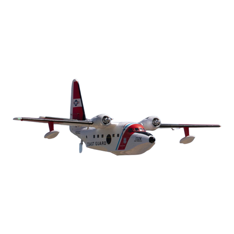
Avios C-130V2 User manual

Please read this manual carefully before operating this plane.
INSTRUCTION MANUAL
For intermediate to advanced pilots

1. Please read this manual carefully and follow the instructions before you use this product.
2. This airplane is not a toy, due to it's advanced flying qualities it is only suitable for experienced
pilots. If you are a novice then please only operate with the assistance of an experienced pilot.
3. Not recommended for children under 14 years old.
4. Please set up this plane according to the instructions and make sure you keep your hands and
other parts of your body out of the way of the rotating propellers at all times. Failure to do so will
result in damage to yourself and to the airplane.
5. Do not fly in thunderstorms, strong winds or wet weather.
6. Never fly R/C planes where there are overhead power lines, automobiles, airports, railway lines
or near a highway.
7. Never fly R/C planes where there are crowds of people or over organised games. This airplane
requires a very flat landing and take-off area that is clear of trees and other obstacles.
Remember safety is the responsibility of the pilot.
8. Do not attempt to catch the plane when you are flying it.
9. The operator will bear the full responsibility of flying and the proper operation and usage of
this model. We at HobbyKing will not be responsible for any liability or loss due to improper use
of this model.
SAFETY INSTRUCTIONS

1
Beloved worldwide, this versatile American four-engine turboprop aircraft has been used in many
guises over its long period in service. Originally it was designed as a troop, and cargo transport
aircraft, but very quickly found uses in a variety of other roles.
The Avios C-130 V2 is available in two brand new color schemes, the classic US Coast Guard
scheme of hi-viz orange and white with scale decals, or a typical civilian cargo plane scheme in red,
white, and blue. Both stand out really well in all skies, and both schemes are lighter in weight than
previous versions. Features include pre-installed motors, ESCs, servos, retract landing gear with door
sequencer, working cargo door, cabin light, nav lights, etc. The V2 also includes an improved rudder
pushrod system with a rear-mounted servo which is lighter, and more direct.
AVIOS presents the only true scale representation of the mighty C-130 turboprop aircraft,
and in its V2 form, they are even better to fly.
INTRODUCTION:
- Propeller: 4 off 6.5x5 4 blade
- Servos: 6 x 9g
- Battery: 2200mAh 4S (14.8V) Recommended/not supplied
- Radio system: Turnigy T-6A Transmitter and Receiver
SPECIFICATIONS:
- Wing span: 1600mm
- Length: 1195mm
- Flying weight: 2350g (inc battery)
- Speed Control: 4 x 18A Brushless ESC
- Power: 4 x 2627-1000KV Brushless Motors
- Included: Retractable landing gear, flaps, and lighting system
C-130 FEATURES:
- This beautiful model is an accurate 1 : 25 scale replica of the C-130.
- Electronic retractable scale landing gear with pre-programmed sequencing geardoors which
operate close to the full scale. It's all fully assembled and tested by skillful factory technicians.
- Scale like operating fowler flaps for short take off and landing
- Four powerful brushless motors provide tremendous power for short take offs and steep climb
outs just like the full scale.
- The iconic 4 blade propellers ( 2 x CW 2 X CCW ) which come with this kit are highly efficient,
powerful and true to scale
- The working C-130 cargo door can be operated by an aux channel on your computer radio.
Good for any candy drops events at the flying fields! A cabin light is also added and it can be
switched on/off automatically when the door is opened and closed.
- Equipped with super bright navigational lights and landing lights which can be seen even in
bright sunlight.
- Wings have special connectors built-in for quick and easy setup at the flying field.
- Scale detailed accessory plastic parts such as windshield wipers, pitot tubes and dew point
sensors are also included in this kit.
L
2
CONTENTS
1. FUSELAGE
2. MAIN WING
3. HORIZONTAL STABILIZER
4. VERTICAL STABILIZER
5. PROPELLERS
6. AUXILIARY TANKS
7. WING JOINER
8. ACCESSORY PACK
9. DETAIL PARTS
10. SCALE ACCESSORIES
11. SPINNER BACKPLATES
12. METAL TAIL ATTACHMENT RODS
13. DISPLAY CARGO RAMP

ASSEMBLY
1. Select the main fuselage body.
2. Install the metal rods into the carbon sleeves at the rear of
the fuselage as shown.
3. Metal rods shown in place.
3
L

4. Get the rear fuselage/horizontal stabilizer section ready.
6. Locate the assembly fully into the rear of the fuselage so
that there is no gap.
5. Slide the assembly onto the metal rods as shown..
4

5
7. Install the vertical stabilizer spigots into the corresponding
slots in the rear of the fuselage assembly.
8. Ensure the vertical stabilizer is fully seated into the slots in
the fuselage assembly.
9. Use the supplied 3mm x 20mm, and 3mm x 25mm screws to lock the
vertical stabilizer to the fuselage assembly. Please note: The longer
3mm x 25mm screw should be installed at the front, just behind the
cargo bay door as shown above..
3mm x 25mm
3mm x 20mm
L

11. Slide through the fuselage the carbon fiber main wing spar.
12. Get the wings ready to slide onto the main wing spar.
6
10. Install the supplied rudder control horn and pushrod as shown
in the picture above.
Please note: The Z link goes to the servo horn, and the ball link
to the rudder horn.

L
1
13. Slide both wings onto the main wing spar.
14. Push both wings up against
the fuselage wing roots, make
sure the electrical connectors
on the wings line up and plug
in correctly.
15. Insert the 4 off 3mm x 10mm
screws into the fuselage wing
roots as shown, if possible, use
a Hex key with ball end to
tighten the screws.
Note: Be careful not to make any
dents in the fuselage when
tightening the screws.
3mm x10mm
7

16.The propeller adapters are factory fitted, worth checking at this point
that they are tight and secure.
17. Install the propellers onto the shaft and spinner backplate, secure
in place with the supplied Hex screws. Once again, apply some thread
lock to the screw threads for security..
8

L
18. Install the outboard flap pushrod linkages to the flaps as shown.
Ensure the Z link goes to the servo horn, and the ball link goes to
the flap horn.
19. Install the elevator pushrod linkage to the elevator as shown.
Once again, ensure the Z link goes to the servo horn, and the ball
link to the elevator horn.
9

Figure 1 Figure 2
20. Connect the UBEC cables to the power cables in the fuselage as shown
in Figures 1 & 2 above. Please pay careful attention to the polarity, and
also ensure that all the pins are fully seated into the socket.
10

11
L
RADIO CONTROL SETUP
Please also study your computer radio instruction manual carefully for the programming and
the proper setup of each function on this airplane.
Flaps setting procedure:
Please do not have the flap control linkages attached until you have the radio set up done.
Once you have set up your radio you may install the control linkages and fine tune the flap
control surface travels evenly on both sets of flaps on both wings.
1.Switch on your radio, press menu and go to the Aircraft Type, choose a type with a 2 aileron and
2 flap setup. After that, assign a 2 way switch for the flap channel and an aux channel with which
to operate the outboard flaps and inboard flaps.
2.Flap (outboard flap} Flap 2 (inboard flap)
3.Plug the Flap servo leads into the designated channel outputs of your receiver according to the
channel assignment of your radio.
4.Connect a flight battery pack to the ESC.
5.Go to the Flap setup menu.
6.In the menu, set the Flap and Flap 2 value to 40% of the total travel as a starting point. Please
also check at this time that the servo travel and direction of all the flap servos are operating with
the same travel and in the same direction. If not please reverse any servo(s) that are traveling in
the wrong direction and adjust the throws.
7.Adjust the servo arm until it reaches an angle of about 20 degree by using the sub trim on the
radio. Then install the servo arm and flap control linkage to one side of the outboard flap. The Z
link should be installed on the second hole from the servo output shaft. Install the ball link socket
to the flap control horn with the supplied screw and lock nut.
8.First adjust the flap in the retracted position. Go into the menu and adjust the value until you see
the flap is fully retracted. There might be some buzzing sound coming from the servo, if so adjust
the end point until the buzzing stops. Once satisfied with the retracted setup, we then move next
to the flap deployment.
9.Flip the flap switch to the extended position, go into the menu and adjust the end point value until
the flap has traveled about 45mm down. Flip the switch to the middle position then adjust the sub
trim until you get 30mm down for mid-flap. Do not allow the outboard flaps to exceed the
indicated throws shown on Page #21 as this might cause difficulties in controlling the plane when
the flying speed gets low. When you are satisfied with this setup you may proceed to do the
same on the other side.
10.Repeat the above set up from #7 to #9 for the inboard flaps, but set them at 22mm for full-flap,
and 11mm for mid-flap .
11.You may also adjust the ball socket on the linkages to ensure all the flap control surfaces retract
and deploy evenly.
NOTE:

12.Double check to ensure all the flap control surfaces are operating in the same manner.
13.Pics#1-3 below shows the inboard and outboard flaps when fully deployed.
Pic #1 Pic #2 Pic #3
CARGO BAY DOOR SETTING PROCEDURE:
1.Switch on your radio. You can either assign a 2 way or a 3 way switch to a free channel to
operate the cargo bay door.
2.Then go into the end points set up page.
3.Adjust both end points to approximately 30% of the total travel on either side.
4.Plug the cargo bay servo lead ( brake) into the selected channel on the receiver.
5.Leave the cargo bay door half open and power up the receiver.
6.The door should not move too much if the end points have been adjusted correctly.
12

L
To Test.
Cycle the retractable landing gear once to ensure it is operating in the correct
sequence.
Flick the retract switch to the wheels down position t should operate normally with
all the wheels in the down position.
Flick the retract switch to the retracted position, it will retract normally with all the
wheels retracting and with all the gear doors clos .
When you need to replace a fresh battery pack after a flight please follow the
procedure below.
The landing gear should be in the fully retracted position. (with wheels retracted
and wheel doors closed).
the battery to the power input cable.
Cycle the gear switch once.
You will see all the gear doors open and wheels come down, they will then retract,
and landing wheel doors will close.
Landing gear radio setup has been completed.
Radio set up for landing gear and door sequencer.
Turn the plane upside down and put the C-130 ideally on a plane stand.
Note: This set up need to be adjusted carefully a stalled cargo bay door servo
will drain the battery excessively even burn the servo motor when
the cargo bay door is opened or closed beyond the mechanical end points.
For a way switch setup
Adjust the end point so that with the switch position selecting the door closed
the door is flush with the fuselage and there is no buzzing from the servo.
Flick the switch to the door down position and adjust the end point so that the
door just misses the ground.
For a way switch setup
Flick the switch to the door position and adjust the end point value until
is flush with the fuselage and there is no buzzing from the servo.
Flick the switch to the door halfway open position and adjust the end point value
so that the door is level to the fuselage main axis.
Flick the switch to the door down position and adjust the end point value so that
the door just misses the ground.
13

Note: Whenever the battery pack is unplugged from the power input cable on the
C-130 then please cycle the retract switch once to let the system re-learn the
program sequence. Cycle the landing gear (extend and retract) once to
ensure it operates smoothly without any issues.
Throttle calibration instructions.
When you use the ESC's for the first time, we recommend you calibrate them to your
radio system, this will improve the throttle response. Please see below the following
steps of how to set it up.
Note: that it is safer to ask someone to help and hold the plane
for you when performing the ESC throttle calibration.
Set the end points of the throttle function on you transmitter to 0% at zero throttle
and 100% at full throttle.
Power on your transmitter and your throttle stick to full throttle, 100%.
Connect the flight battery to your C 130, you will hear tones “W V” from the motors
to confirm the end point after approximately 3 seconds.
Move the throttle stick back to 0% immediately after you hear the “W V” tones.
This completes the throttle calibration procedure.
Unplug the flight pack then switch off the transmitter.
Before flying ensure the battery is fully re-charged.
Put the C-130 on a plane stand.
With landing wheels down (gear switch should be in gear down position).
Replace the depleted battery with a fresh battery pack and it to the power
input cables.
Cycle the gear switch once.
Only the nose gear door will open and close again (Nose wheels and main wheels
will remain in the down position).
Flick the retract switch to the retracted position. It will operate normally with all the
wheels retracting and all the doors clos .
14

L
SCALE DETAIL PARTS ASSEMBLY:
The following pictures show the fitting of the windshield wipers.
15

The following pictures show the fitting of the pitot tubes.
16

17
L
The following pictures show the fitting of the antenna's.

18
The following pictures show the fitting of the dew point sensor.
Table of contents
Other Avios Toy manuals

Avios
Avios Hawker Sea Fury FB11 EPO Warbird User manual

Avios
Avios BushMule V2 User manual

Avios
Avios Albatross HU-16 User manual

Avios
Avios EXTRA 330 LX User manual

Avios
Avios MIG-17 FRESCO User manual

Avios
Avios Exra330 LX User manual

Avios
Avios Zazzy User manual

Avios
Avios KingTwin 1700 User manual

Avios
Avios Bush Mule User manual

Avios
Avios Albatross User manual
Popular Toy manuals by other brands

Tiger
Tiger Hitclips FM Radio Cartridge 59610 Instruction

TP Toys
TP Toys Splash and Play Happy Chef Wooden Mud... Instructions for assembly, maintenance and safe use

RC GROUP
RC GROUP Flaglor Sky Scooter Build guide

Eduard
Eduard Mi-24 interior manual

Jamara
Jamara largos XXL instruction manual

Topmodel
Topmodel MALADIETS manual