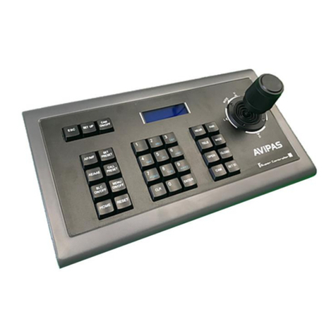
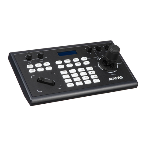
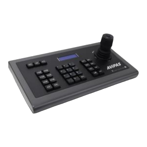
Avipas AV-3207 User manual

Model: AV-3207
4D Serial & IP Joystick Controller
User Manual
V1.1
Please read this user manual
thoroughly before using.
www.avipas.com


1
1. Security Guidance........................................ .....................................................................2
1.1 Cautions.........................................................................................................................................2
2. Check Before Using..........................................................................................................3
2.1 Packing List.................................................................................................................................3
2.2 The Wiring...................................... ........ ...................................................................................3
2.3 Bottom Dialing Switch...........................................................................................................3
3. Keyboard Description....................................................................................................4
3.1 Functional Features..................................................................................................................4
3.2 Technical Specifications........................................................................................................4
3.3 Product Dimension........................................................................................................ ..........5
3.4 Interface Description...............................................................................................................5
3.5 Display Screen ..................... ........ ........ ..................................................................................6
3.6 Button Function.........................................................................................................................6
4. Menu Setting.........................................................................................................................11
4.1 Menu Instructions....................................................................................................................11
4.2 Menu Options............................................................................................................................11
5. Wiring diagram..................................................................................................................12
5.1 Connection in network mode.............................................................................................12
5.2 Connection in RS232 mode................................................................................................13
5.3 Connection in RS422 mode................................................................................................13
5.4 Connection in RS485 mode................................................................................................14
5.5 Cascade in RS232, RS422, RS485 mode.....................................................................15
6. WEB User Interface.......................................................................................................17
6.1 Login Instruction.....................................................................................................................17
6.2 Device Control.........................................................................................................................17
6.3 Network Parameter................................................................................................................18
6.4 Firmware Upgrade.................................................................................................................18
6.5 Reset Options...........................................................................................................................18
6.6 Account.......................................................................................................................................19
7. Frequently Asked Questions..................................................................................20

2
1.1 Cautions
Preface:
This manual introduces the functions, technical specifications and operations of the
serial/IP controller. Prior to installation and usage, please read the manual thoroughly.
Precautions:
This product can only be used in the specified conditions in order to avoid any
damage to the controller:
1. Do not subject the controller to rain or moisture. Do not subject the controller to
corrosive gas or liquid.
2. Do not dismantle the controller. Otherwise, you may risk receiving an electric
shock. In case of unintended equipment operation, please contact an authorized
engineer.
3. Do not operate the controller under unspecified temperature, humidity or power
supply.
4. Please use soft and dry fabric for the clean purpose.
5. Please use this product within the suitable temperature and humidity range.
Operating temperature: -10℃~ 50℃, humidity ≤ 80%.
Electronic Safety:
1. Installation and operation must accord electric safety standard.
2. Avoid pressure, vibration or soakage during transport, storage, installation and
usage.
3. The power supply of this product is DC 12V, max electronical current is 1A. It is
recommended to use with the power adapter included in the package.
Power supply polarity:

3
2.1 Packing List
When unpacked, check if all supplied accessories are included:
Control keyboard ········································································ 1PCS
Power Adapter ············································································ 1PCS
Power Cord ··············································································· 1PCS
RS232 Cord ··············································································· 1PCS
User Manual ·············································································· 1PCS
2.2 Wiring
2.3 Bottom Dialing Switch
Bottom dial control
Mode
SW-1
SW-2
Description
1
*
OFF
ARM Upgrade
Mode
2
*
ON
Normal Working
Mode
SW-1 is reserved, no function defined

4
3.1 Product Features:
1. Support multiple network interfaces, including RS232, RS422 and RS485.
2. Supports VISCA Serial, Pelco-P, P elc o-D, VISCA over IP, VISCA TCP, VISCA
UDP, ONVIF, and NDI (optional) protocols.
3. Equipped with seven camera shortcut control buttons.
4. Support button keys backlight.
5. Support set, call and clear presets.
6. Support camera PTZ speed adjustment.
7. Support daisy chain function (Max 7 cameras)
8. Support camera On Screen Display menu.
9. Supports standard POE (Power Over Ethernet).
10. Support 10M, 100M adaptive network RJ45 connection.
3.2 Technical Specifications
:
Parameters
Indicators
Control Interface
RJ45, RS232, RS422, RS485
RJ45
Ethernet port, POE(IEEE802.3af)
RS232
DB9 male connector
RS422
3.81 spacing terminal, T+, T-, R+, R-
RS485
3.81 spacing terminal, T+, T-
Support Protocols
VISCA Serial, Pelco-P, Pelco-D, VISCA over IP,
VISCA TCP, VISCA UDP, ONVIF, NDI (optional)
Upgrade Interface
Type-C
Display Screen
3.12" OLED screen, blue light, 256×64 pixels
Display Screen
Working power
12V⎓1A
Working Temperature
-10℃~50℃
Working Humidity
≤80%
Storage Temperature
-20℃~60℃
Storage Humidity
≤90%
Size
320.5mm×156.5mm×118mm
Weight
1.05kg

5
3.3 Product Dimension
:
3.4 Interface Description
:
1. Lock Port
5. Ethernet Port
9. Button
2. Type-C Upgrade Interface
6. Power Input
10. Joystick
3. RS232 Interface
7. Indicator light
11. Display screen
4. RS485 Interface
8. Knob
12. Dial switch

6
3.5 Display Screen
:
3.6 Button Function:
3.6.1 Shortcut Selection Area
【
CAM1
】
~
【
CAM7
】
Select the corresponding camera.
3.6.2 Adjustment Knob and 3A Setting Area
【
AE MODE
】
When the "AUTO" indicator light is on, the controller is under
auto exposure mode. When the "AUTO" indicator light is off, the controller can

7
switch between Manual/Shutter/Iris/Gain mode. The knobs on the left side can be
used to adjust parameters for Shutter, Iris, B/R Gain and Brightness.
【
WB MODE
】
When the "AUTO" indicator light is on, the controller is under
AUTO/ATW m ode . When the "AUTO" indicator light is off, the controller can
switcher between Manual/Indoor/Outdoor/Sodium lamps/Fluorescent lamps modes.
The user can adjust red gain and blue gain value through the first two knobs on the left
side of the keyboard.

8
【
TRIGGER
】
In One-push mode ("WB PUSH" light is on), the automatic white
balance will turn on.
【
AF/MF
】
The "AF" indicator light will turn on under Auto Focus mode.
Otherwise, the controller is under Manual Focus mode. Focus +/- can be adjusted by
the third knob on the left side of the keyboard.
Note: When exposure and focus are under manual mode at same time, then the
3rd knob will priority to adjusting the focus.
【
PUSH FOCUS
】
Autofocus once.
3.6.3 Numeric Button Area
【
0~9
】
+
【
SET
】
Set the presets.
【
0~9
】
+ Short press
【
CALL/CLEAR
】
Call the presets.
【
0~9
】
+ Long press
【
CALL/CLEAR
】
Clear the Presets.
Note: Up to 128 presets can be set and recall.
3.6.4 Parameters and Speed Adjustment Area
【-
SHARPNESS
+
/
-
PRESET SPEED
+】
Adjust the sharpness. / Adjust the
preset speed.
【-
WDR
+
/
-
PT SPEED
+】
Adjust the WDR. / Adjust the camera PT speed.
【-
CONTRAST
+
/
-
Z SPEED
+】
Adjust the contrast. / Adjust the camera

9
zoom speed.
【-
SATURATION
+
/
-
ZOOM
+】
Adjust the saturation. / Adjust the camera
lens zoom.
Note: Press the SHIFT button to switch between parameter setting mode and
speed setting mode. The screen will display “S” when SHIFT is pressed.
When "S" is shown on the screen, these 4 buttons mentioned above can be
used for parameter setting.
Otherwise, these 4 buttons can be used for speed setting and zoom.
3.6.5 Other Button Areas
【
BLC ON/OFF
】
Backlight compensation on / off.
【
SHIFT
】
Switch between parameter adjustment mode and speed adjustment
mode.
【
SEARCH
】
Search for IP addresses.
【
HOME/OK
】
Return to the original position of the camera.
【
POWER/RESET
】
Short press to control the camera power, long press to reset
the camera.
【
CMENU/KMENU
】
Short press to open the camera menu, long press to open
the keyboard menu.
3.6.6 Joystick Control
【
Up
】【
Down
】【
Left
】【
Right
】
Use the joystick to control the camera in 4
directions.

10
【
Zoom
+】
Turn the joystick clockwise to zoom in.
【
Zoom
-】
Turn the joystick counterclockwise to zoom out.
【
Lock
】
When controlling the camera and press the "lock" button, the camera
will keep rotating in previous moving direction until the set lock time is exceeded or
the camera rotates to the limit position.

11
4.1 Keyboard Menu Instructions:
Long press CMENU/KMENU button to open the keyboard menu; Move the
joystick Up or Down to view the menu options; Right to enter submenu; Left to return
to the previous page.
Note: Short press CMENU/KMENU can also return to the previous page;
numeric keys 0~9 can set the corresponding parameters in some sections.
4.2 Menu options:
Camera
setting
Camera
The keyboard can set 7 camera addresses: CAM1~CAM7
Protocol
VISCA Serial, Pelco-P, Pelco-D, VISCA over IP, VISCA
TCP, VISCA UDP, ONVIF, NDI (optional)
IP Addr / Address
Set the camera IP address or camera address.
Port / Baudrate
Set the port number or baud rate.
Default port numbers for each IP protocol:
ONVIF: 8000, NDI: 5961, VISCA: 52381
Username
Username setting, default: admin
Password
Password setting, default: admin
Password
setting
New PSD
Create new password.
Confirm
Confirm the new password.
Enable
Enable the new password.
Vers i on
Keyboard firmware version.
System
setting
Language
Chinese/English
Brightness
1~15
Backlight
AUTO/ON/OFF
Screen Prt
10s~180s
DHCP
OFF/ON
Local IP
192.168.001.180(default)
Mask
255.255.255.000
Gateway
192.168.001.001
PTZ
setting
Pan Reverse
Reverse the control direction.
Tilt Reverse
Reverse the control direction.
Preset PT Spd
Set preset PT speed: 5~24
Preset Z Spd
Set preset Zoom speed: 1~7
Focus Speed
Set focus sensitivity: 0~7
Lock Time
Set lock time: 2~20(s)

12
5.1 Connection in network mode:
5.1.1 The keyboard controller connects with camera through PoE switch: In the
same LAN, set the same network segment, correct protocol, IP address and port
number, then you can control the camera.
5.1.2 The keyboard controller connects with camera directly: Connect the
controller with camera directly via Ethernet cable, set the same network segment,
correct protocol, IP address and port number, then you can control the camera.

13
5.2 Connection in RS232 mode:
Connect the controller with camera via RS232 cable, set correct protocol, address
and baud rate, then you can control the camera.
Line Sequence
:
Connect the controller with camera via RS232 cable. Connect
controller pin 1 RXD with camera input interface TXD; connect controller pin 2 TXD
with camera RXD; connect controller pin 3 GND with the camera GND.
5.3 Connection in RS422 mode:
Connect the controller with camera via RS422 cable, set correct protocol, address
and baud rate, then you can control the camera.
DB9 Male
(Pin type)
Pin Number
2
3
5
1,4,6
7,8
Signal
Definition
RXD
TXD
GND
Internal
connection
Internal
connection

14
Line Sequence
:
Use the RS422 connection. Let the controller pin 1 TXD +
connects to the camera's RXD-, the controller pin 2 TXD - connects to the camera's
RXD +, the controller pin 3 RXD + connects to the camera's TXD -, the controller pin
4 RXD - connects to the camera's TXD+.
Note: Some cameras do not support RS422 control.
5.4 Connection in RS485 mode:
Connect the controller with camera via RS485 cable, set correct protocol, address
and baud rate, then you can control the camera.

15
Line Sequence
:
Use the RS485 connection. Let the controller pin 1 TXD +
connected to the camera RXD-, the controller pin 2 TXD- connected to the camera
RXD +.
5.5 Cascade in RS232, RS422, RS485 mode
:
Connect the cameras in daisy chain as shown below:
Line Sequence
:
Use RS232 cascade connection. Connect the output of the
controller with the input port of first camera; connect the output port of first camera

16
with output port of second camera. Set correct protocol, address, baud rate, then you
will be able to control the cameras.

17
6.1 Controller Web User Interface
Connect the controller with PC
through Ethernet cable. Make sure the
controller is in the same LAN with your
PC. (For full instruction about how to
access controller via IP, please refer to
How-to material in our website:
www.avipas.com). Open a browser, enter
controller’s IP address in the address bar
(default: 192.168.1.180). Login with default username and password: admin/admin.
In the web user interface, you can change controller’s settings in system
configuration page, as shown below:
6.2 Device Control
6.2.1 Device Search
Searching for devices within same LAN and add to Device Configuration section;
Or enter camera’s IP addresses/protocols manually.
6.2.2 Device Configuration
Modify configured devices’ IP address, protocol and port number.

18
6.3 Ethernet Parameter
Set the network parameters of the
controller, including DHCP switch, IP
Address, Netmask, Gateway, DNS,
HTTP Port.
6.4 Firmware Upgrade
The current firmware version will display
on the screen. For firmware upgrade, please
choose ‘select file’ and upload corresponding
firmware files. Please do not power off during
the upgrade process.
6.5 Reset Options
Reset/Reboot: Resets all parameters and
reboots the device.
Reboot: Reboot the device.
Table of contents
Other Avipas Controllers manuals
Popular Controllers manuals by other brands

sisel
sisel ENDA ET1413R quick start guide

WEIGL
WEIGL ProCommander LTC instruction manual

Watlow
Watlow Single and Dual Loop Controller Series PD Specifications

ABB
ABB ControlMaster CM10 Commissioning instructions

DEEP SEA ELECTRONICS
DEEP SEA ELECTRONICS DSE4610 installation instructions

Mindsensors
Mindsensors GlideWheel-M user guide

Danfoss
Danfoss ECL Comfort 310 operating guide

Mitsubishi Electric
Mitsubishi Electric Central Controller G-50A Technical manual

Jorc
Jorc FLUIDRAIN-COMBO-QUICKSET Installation & maintenance instructions

Toro
Toro OSMAC RDR Satellite Controller installation instructions

Honeywell
Honeywell Satronic DVI 980 manual

Hangarbot
Hangarbot DCN-8000-17-v1 installation manual