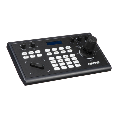
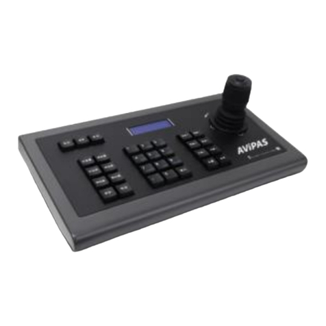
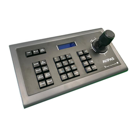
Avipas AV-3106 User manual

Model: AV-3106
Keyboard Controller
User Manual
V3.01
(English)
Please read this User Manual
throughout before using.
www.avipas.com

CONTENTS
1. Summary-----------------------------------------------------------------------------------------------------1
1.1 Notice --------------------------------------------------------------------------------------------------1
1.2 Functions and characteristics-------------------------------------------------------------------------1
1.3 Technical data ------------------------------------------------------------------------------------------1
2. Keyboard Connections ------------------------------------------------------------------------------------2
2.1 Interface instructions ---------------------------------------------------------------------------------2
2.1.1
RS422 and RS485 ------------------------------------------------------------------------------ 2
2.1.2
Power supply port----------------------------------------------------------------------------2
2.1.3
EIA RS232 interface-------------------------------------------------------------------------2
2.1.4
RJ45 interface--------------------------------------------------------------------------------2
2.2 DIP switches settings---------------------------------------------------------------------------------3
2.3 Matrix connections -----------------------------------------------------------------------------------3
2.3.1
RJ45 local connections -------------------------------------------------------------------3
2.3.2 RS422 remote connections -----------------------------------------------------------------3
2.4 Connect to a dome directly-------------------------------------------------------------------------- 4
2.5 Connect to a DVR----------------------------------------------------------------------------------4
2.6 Connection to the system----------------------------------------------------------------------------- 4
3. Keyboard Operation Manual
---------------------------------------------------------------------- 6
3.1 Current-carrying capacity --------------------------------------------------------------------------6
3.2 LCD ----------------------------------------------------------------------------------------------------6
3.3 Use joystick to control dome ------------------------------------------------------------------------ 6
3.4 Change object dome ---------------------------------------------------------------------------------- 7
3.5 Lens control ------------------------------------------------------------------------------------------- 7
3.6 Set dome functions------------------------------------------------------------------------------------ 7
3.6.1
Preset-------------------------------------------------------------------------------------------7
3.6.2
Scan --------------------------------------------------------------------------------------------7
3.6.3
Pattern------------------------------------------------------------------------------------------ 8
3.6.4
Tour -------------------------------------------------------------------------------------------- 8
3.7 Call the dome main menu ------------------------------------------------------------------------------- 8
3.8 Control the matrix -------------------------------------------------------------------------------------8
3.8.1
Switch dome in order ---------------------------------------------------------------------------- 8
3.8.2
Call the matrix main menu --------------------------------------------------------------------8
3.8.3
Confirm after setting--------------------------------------------------------------------------- 8
3.8.4
Change object monitor ------------------------------------------------------------------------8
4.
Keyboard Menu ---------------------------------------------------------------------------------------- 9
4.1
keyboard index settings --------------------------------------------------------------------------- 9
4.1.1
Set ID number --------------------------------------------------------------------------------9
4.1.2
Set baud rate ------------------------------------------------------------------------------9
4.1.3
Set password ------------------------------------------------------------------------------9
4.1.4
Joystick calibrations ------------------------------------------------------------------- 10
4.1.5
Multi-keyboard connection settings -----------------------------------------------------11
4.2
Dome setups -----------------------------------------------------------------------------------------11
4.2.1
Set preset positions ------------------------------------------------------------------------- 11
4.2.2
Horizontal scan------------------------------------------------------------------------------ 11
4.2.3
Pattern scan ---------------------------------------------------------------------------------- 12
4.2.4
Dome tour -------------------------------------------------------------------------------------12

4.3 Alarm box control ---------------------------------------------------------------------------------- 13
4.3.1
Set the alarm input channel and thealarm spot------------------------------------------ 13
4.3.2
Set alarm ON/OFF status and reset alarmtime-------------------------------------------13
4.3.3
Reset the alarm input manually ------------------------------------------------------------14
4.3.4
Resume factory default settings ----------------------------------------------------------14
4.4 Protocol settings ------------------------------------------------------------------------------- 14
4.4.1
Pelco matrix model -------------------------------------------------------------------------14
4.4.2
Direct control model------------------------------------------------------------------------14
4.4.3
DVR control model ------------------------------------------------------------------------- 15
4.5 Display the keyboard information --------------------------------------------------------------- 15
4.6 Exit keyboard menu --------------------------------------------------------------------------------15
5.
Appendix ----------------------------------------------------------------------------------------------16
5.1 RS485 bus line basics ------------------------------------------------------------------------------ 16
5.2 Keyboard shortcut operation manual-------------------------------------------------------------17
6.
Keyboard Menu Index ----------------------------------------------------------------------------------- 18
7.
Maintenance service terms--------------------------------------------------------------------------------19


Summary
1. Summary
AV-3106 is a universal keyboard for security
monitoring series. It can control integrated dome cameras
owing to all kinds of protocol matrices and DVR. This
controller is equipped with 3D joystick, which can control
the camera panning and the zoom of lens. With the backlit
LCD screen, the controller can display the current operation,
the name of the control protocol, the current dome ID, the
current monitor ID and the state of the joystick. The user can
control the CCTV system more easily.
1.
1 Notice
●
Please read this manual thoroughly before use,
and keep it handy for future reference.
●
Do not use or store AV-3106 in the environment
where the product is exposed to rainwater,
moisture vapor, salty water, oil, etc.
●
Do not place the controller close to any
exothermic object for a long time.
1.2
Functions and Characteristics
●
Using a RS485 bus line, this keyboard can connect
up to 31 domes in the direct control mode.
●
This keyboard is compatible with all kinds of
protocols.
●
The user can control the aperture, zoom and
magnification.
●
The user can set and call the preset menu, run scan
or pattern and tour functions.
●
The user can work with the matrix, which can be
used to control the dome indirectly.
●
The user can set alarm trigger and alarm linkage.
●
This keyboard is equipped with a 3D joystick and a
large LCD screen.
1.3
Technical Data
◆
Electrical
Input voltage: 9V~12V AC/DC
Rated power: 2.5W
◆
Communication
Communication interface:
RS485×1, RS422×1, RS232×1, RJ45×1
Communication frequency:
2400bps, 4800bps, 9600bps
Communication distance:
1.2km(only with RS485 and RS422)
◆
Operational Environment
Operating temperature:0℃~40℃
Relative humidity: less than 90%
◆
Physical Properties
L*W*H=378*160*98(mm)
Weight:1.3kg(Net Weight)

Connection
2.
Keyboard Connections
2.1
Interfaceinstructions
AV-3106 is equipped with all kinds of
communication interfaces: RS232, RS422, RS485,
RJ45. The user can find them on the back of the
keyboard. With proper connections, this keyboard can
control target devices.
2.1.1
RS485 and RS422 interfaces
RS485 and RS422 interfaces are 6-bit ribbon cable
connections on the keyboard. RS485(A+, B-) can be
used to connect a dome, in order to control the dome
directly with the keyboard. RS485(A+, B-)can be used
to connect to a DVR or other keyboard when the dome is
controlled via matrix. RS422 (T+, T-) is the “sending
signal” mode, while RS422 (R+, R-) is the “receiving
signal”mode, and both modes can be used to connect to a
matrix, DVR and so on.
2.1.2
Power supply port
The power supply port is used to connect the
keyboard to 9V-12V DC/AC power. The keyboard itself is
equipped with an adaptor which converts 230VAV to
9VDC.
2.1.3
EIARS232 interface
EIA RS232 interface is used to expand the
functions to control the menu handler, DVR, PC and so
on.
2.1.4
RJ45 interface
RJ45 interface is the standard network interface
which is mainly used for connecting the matrix for short
distance use (less than 7.6m). For more details, please
see “2.3 Matrix connections”.
2.2 DIP switch settings
There is an 8-bit DIP switch on the back of this
keyboard. Among the 8 bits, 1-7 bits are invalid, and the
8th bit is for end-of-line resistance (120Ω)setting for
RS485 bus line. When the 8th bit is set to “ON”, it
means the end-of-line resistance has been connected into
the system. For more RS485 (A+, B-) bus line setting
information, please see “5.1 RS485 bus line
knowledge”.
Picture 2-1.1
DIP 1 2 3 4 5 6 78
RS232
RS485 RS 422
RJ45
AC/DC 9V-12V
OFF
ON
A+ B- T+ T- R+ R-
DIP Switches
EIA RS232
Interface
6-bit Ribbon Cable
Connection
RJ45
Power Supply Port
Picture 2-1.2

Connection
2.3 Matrix connection
The keyboard can control matrices for PELCO
CM6700 and CM6800. In order to introduce the
connection between the keyboard and the matrix, take
connection to PELCO CM6700 matrix as an example.
There are two kinds of keyboard connection
interfaces on the back plate of CM6700 matrix: one is the
local keyboard connection interface RJ45 (“LOCAL
NOTICE
1. RJ45 local connection: the distance between the
keyboard and the matrix is less than 7.6m.
2. RJ45 interface is powered by 12VAC, which can
at the same time power the keyboard which is
connected to CM6700 matrix.
KEYBOARD”), which can control a single keyboard
within a distance of 7.6m; the other is the remote interface
RS422 (“REMOTE KEYBOARD(S)”), which can connect
to the RS422 interface on the keyboard. The maximum
distance is 1200m.
2. 3. 1 RJ45 local connection
2. 3. 2 RS422 remote connection
Connect one end of RS422 cable to RS422 interface
on the back plate of CM6700 (REMOTE KEYBOARD(s)),
and connect the other end to RS422 interface on the
keyboard. RS422 (R+, R-) on the keyboard corresponds to
matrix interface RS422 (T+, T-); RS422 (T+, T-) on the
keyboard corresponds to matrix interface RS422 (R+, R-).
Please insert one crystal head of RJ45 cable into the
RJ45 interface on the back panel of the keyboard, and
insert the other end into the RJ45 interface (“LOCAL KE-
YBOARD”) of CM6700 matrix.
NOTICE
RS422 remote connection: the maximum distance
between the keyboard and the matrix is 1200m.
Keyboard 1
Pin8 Pin1
Keyboard2
POWER INPUT
AC/DC 9V-12V
Pin1
2
RJ-45 Limb
T+
Pin5
T- 6
RJ45
NC
NC
39V-12VAC/DC
4NONPOLAR 7
R-
8
R+
VIDEO OUTPUTS
RS485
RS422
ALARMS
(1-9) Local Keyboard
A+B-T+T-R+R- ALARMS
(1-18) Remote Keybard( S) RJ45
Keyboard Matrix
T+ R+
T- R-
R+ T+
R- T-
COM1 ( 1-6 )
COM2 (7-12)
CONTROL
OUTPUTS
CM 6700 Matrix
T T R R
+ - - +
Picture 2-3.1

Connection
2.4 Connect to a dome directly
The user can connect the keyboard to a dome via a
RS485 cable for direct control. Make sure that keyboard
DIP switches are set in the direct control mode. To find the
RS485 interface of the dome: The user needs to turn the
metal button inside the hanging plate and open the cover.
There is a 4-Pin control/power socket, and the RS485
interface (A+, B-) can be found following the instructions.
Dome cameras from different manufacturers may
acquire different connections. Please see to the dome
installation manual before connecting to the keyboard.
2.5 Connect to a DVR
The keyboard can be connected to a DVR and a dome
via RS422 interface. RS422 (R+, R-) on the keyboard can
connect RS485 (A+, B-) or RS485 (T+, T-) on the DVR and
RS485 (A+, B-) on the dome separately.
AC24V RS485
A+ B-
RS485 RS422
A+ B- T+ T- R+ R-
Power AC/DC 9V-12V Dome
Keyboard
Picture 2-4.1
AC24V RS485
A+ B-
RS485
RS422
A+ B-
A+ B- T+ T- R+R-
DVR RS485
Power AC/DC 9V-12V Dome
Keyboard
Picture 2-5.1

Connection
Matrix
Co m p uter
(DVR)
2.6 Connect the keyboard in the system
The user can use the keyboard to control the alarm
box, and to connect the dome via the alarm box. Please
see the alarm box user manual for more details regarding
the connections. Every alarm box only can connect to
one dome camera.
The keyboard can control the matrix, and control
the domes indirectly by the matrix (see Picture2-6.1).
When the keyboard is not connected to the matrix, it
connects to a computer (DVR), and controls the dome
(see Picture2-6.2); or the keyboard can also control the
dome directly without DVR.
Several keyboards and dome cameras can be
connected in parallel, and access RS485 bus line. Each
keyboard can control a dome independently. Working in
this mode requires the user to set a main keyboard (the
main keyboard ID is set to 1), and the Baud rate of the
keyboard is set to 9600bps (see Picture 2-6.3).
Keyboard
Dome 1 Dome 2
Picture 2-6.2
In the previous pictures, the connections between
keyboard and keyboard or between keyboard and
computer are all via RS232, however, when the distance
between devices is more than 20m, it is suggested that
RS485 should be used.
Keyboard Dome 1 Dome2
Picture 2-6.1
1.
Using one RS485 cable enables the user to
control up to 32 pieces of equipment. With
that being said, a keyboard can directly control
up to 31 domes.
NOTICE
2.
The system may have up to 4 keyboards
simultaneously, and each keyboard holds a
different ID.
Keyboard1 Keyboard2
Keyboard3
Dome1
Dome2
Dome3
Dome4
keyboard4
Dome5
Dome6
Dome7
Dome8
Picture 2-6.3

Connection
DVR controlling
LCD Numeric zone Function Joystick
Lens Controlling
Picture 3-1.1
3.
Keyboard Operation Manual
This section mainly describes the operations of
keyboard. Notice that different systematic platforms may
not always have the same operation, and for particular
requirements and operations, please refer to the operation
manuals of the dome and the matrix that are being used in
the system.
3.1 Current-carrying capacity
Upon being power on, the keyboard
will auto-test the version number, keyboard ID, baud-
rate, protocol, and will auto-set the object dome and
object monitor to #1. All the information will display on
the LCD.
3.2 LCD
LCD is used to display the basic information of the
keyboard, including the keyboard model, keyboard ID, object
camera, object monitor ID, baud rate, etc. In the last line,
there are keyboard input commands and the joystick
operations (see Picture 3-1.2). When the keyboard is in
operation, the backlight of LCD will light up; after no
operation is going on for 15s, backlight will be off
automatically.
Keyboard V1.02
Keyboard ID: 001
Camera ID: 002
Monitor ID: 001
Protocol: Pelco Matrix
Baud rate: 9600bps
NOTICE
1. When the keyboard is initializing, the
joystick would to return to position 0, and
the user should not pull or tilt the joystick.
Picture 3-1.2
3. 3 Use joystick to control dome
The joystick has two functions: one is to manually
rotate the dome, and the other is to control the menu
settings of the object dome.

Connection
●Tilt the joystick to any direction, and the dome camera
will rotate to the corresponding direction. At the same
time, LCD displays the information at the lower right
corner: “”, which respectively reflects tilt up,
tilt down, tilt right, tilt left. If the joystick tilts to the upper
right corner, then the screen will display such information
as “”. When the joystick returns to the initial location
in the center, the dome stops to rotate immediately.
●When being used to set the menu, the joystick tilting up
means choosing the previous menu; tilting down means
choosing the next menu; tilting right means entering the
current menu or reserving the setting; tilting left means
exiting the menu or discarding the changes.
●The greater the gradient of joystick is, the faster the
dome rotates. By controlling the gradient of the joystick,
the user can control the rotation speed of dome.
By rotating the joystick cap, the user can adjust the
focus of lens: rotating the cap clockwise, the camera lens
moves closer to the object, and at the same time a “ ”
icon will display on the LCD; rotating the cap counter
clockwise, the camera lens moves farther from the object,
and at the same time a “ ”icon will display on the
LCD. When controlling the dome via DVR, rotating the
cap clockwise indicates “Select”; rotating the cap counter
clockwise indicates “Exit”.
Magnification control:Press 【Tele】to get a higher
magnification. Let go to stop.
Press 【Wide】to get a lower magnification. Let go to stop.
Magnification can also be controlled by rotating the joystick.
Focus control:Press 【Far】to manually move the focus
farther away from the object. Let go to stop.
Press 【Near】to manually move the focus closer to the
object. Let go to stop.
Under a normal working mode, auto-focus function is on by
default. The user can choose to manually control the focus using
【Far】and 【Near】.The camera will automatically resume
to auto-focus when no button is being pressed.
Aperture control:Press 【Open】to manually increase
the aperture. When aperture is at its maximum, the screen will show
all white. Let go to stop.
Press 【Close】to manually reduce the aperture. When
aperture is at its minimum, the screen will show all black. Let go
to stop.
3.6 Dome function operation
3.6.1
Preset
●Set preset: 【Set】+【N】+ 【Preset】
●Call preset: 【N】+ 【Preset】
【N】indicates the preset number.
3.6.2
Scan
●Set left limit:【Set】+【1】+【Scan】
●Set right limit: 【Set】+【2】+【Scan】
●Run scan: 【1】+【Scan】
If the user would like to change the speed of scan, enter
the menu to setup.
3.4 Change object dome
The user can change the object dome camera by using
the combination 【N】+ 【Cam】.
【N】indicates a numeric key (the same indicator will
be used throughout this manual). The user needs to input
the dome ID, and then press 【Cam】to change object
dome.
3.5 Lens control
3.6.3 Pattern
●Set pattern path: 【Set】+【N】+ 【Pattern】
+Path+【Set】+【0】+【Pattern】
Press 【Set】, then input pattern NO. (1-4), and press
【Pattern】to enter the pattern path setup. The dome will
record a series of motions and positions, and after
recording is complete, press 【Set】again, then press【0
】+ 【Pattern】. Pattern setup is complete.

Connection
●Run pattern:【N】+ 【Pattern】
Input pattern NO. (1-4), then press 【
Pattern】, the corresponding pattern will run.
3.6.4 Tour
Run tour:【N】+ 【Tour】/【Tour】
Press tour number, then press 【Tour】, run
tour. If system has only one tour path, then press
only 【Tour】to run the tour directly.
If the user would like to set a tour path, enter
the menu to setup.

Connection
3.7 Call the dome main menu
【9】+【5】+【Preset】: call the main menu of
object dome, and the menu will display on the object
monitor. Please refer to the dome manual for more details
regarding how to set the dome menu using a keyboard.
3.8 Control the matrix
3.8.1
Switch the domes in order
A matrix can connect up to 16 domes. The user can
switch the dome forward or backward sequentially.
【Prev】: switch to the previous dome.
Press 【Prev】to switch to the previous dome in single step;
press 【Prev】and hold it for 2s, it’ll jump over 16 domes in a
backward order.
【Next】: switch to the next dome.
Press 【Next】to switch to the next dome in single step; press
【Next】and hold it for 2s, it’ll jump over 16 domes in a
forward order.
【Stop】: stop the switch process.
3.8.2
Call the main menu ofmatrix
【Shift】+ 【Set】:call the main menu. The menu will
display on the object monitor. Please refer to the matrix manual
for more details regarding how to set the matrix menu using a
keyboard.
3.8.3
Confirm after setting
【Enter】:after the matrix is set, press 【Enter】to
confirm the settings. Please refer to the matrix manual for more
details.
3.8.4
Change object monitor
【N】+ 【Mon】: input the monitor ID, then press 【
Mon】. Both the image from the dome and the main menu of
the dome that is being controlled by the keyboard will display
on the object monitor.
When the keyboard is working in Pelco matrix mode
(refer to 2.2 DIP switches settings), it can control the
dome or the monitor via matrix.
NOTICE Only in Pelco matrix mode, can the keyboard
perform the control commands of matrix.

Connection
4.
Keyboard Menu
The keyboard menu controlling
Press 【Set】, and hold it for 2 seconds, the keyboard
main menu will show on the LCD (see Picture 4.1-1). The
main menu should be called before any setup.
Press the numerical key or move the joystick up/down
after entering the main menu, the user can select and enter
the sub-menu for setups.
2.
Press【1】to enter Keyboard setup
The LCD screen is shown below (see Picture 4.1.1-
2).
Picture 4.1.1-2
3. Press【1】to enter Set keyboard ID
The LCD screen is shown below (see Picture 4.1.1-
3).
Picture 4.1.1-3
Picture 4.1-1
Save the settings
Choose the numerical key in according to
the menu, then enter the sub-menu; press 【Enter】to
confirm the changes. LCD will display “success” after
saving the setting successfully.
Press the corresponding numerical key (1-64), then
press 【Enter 】. The LCD screen will show the message
below (see Picture 4 .1.1-4), and keyboard ID is set
successfully.
Return to the previous menu
Press 【Prev】or move the joystick to the left,
Picture 4.1.1-4
it’ll return to the previous menu.
4.
1 Keyboard ID settings
4.1.1 Set keyboard ID
1. Enter the main menu
The LCD screen is shown below (see Picture
4.1.1-1).
The screen will show 【Error】if the number
entered is invalid (see Picture 4.1.1-5).
Picture 4.1.1-5
4. Press 【Prev】or move the joystick leftwards to
go back to the previous menu
Picture 4.1.1-1
Input keyboard ID:
1. Set keyboard ID
2. Set baudrate
3. Set password
4. Joystick calibrate
5. Multi-keyboard state: ON
press Prev to go back
Error!
1.Keyboard setup
2.Dome setup
3.Alarm box setup
4.Protocol select
5.About keyboard
6.Exit menu
Success!
The default ID of the keyboard is 1;
The ID number must be 1 when working in the
single-keyboard mode; It can connect up to 4
keyboards when working in the networking mode.
Make sure there is only one keyboard’s ID is set
NOTICE to 1. Otherwise nokeyboard will work
normally.
1.Keyboard setup
2.Dome setup
3.Alarm box setup
4.Protocol select
5.About keyboard
6.Exit menu

Connection
4.1.2 Set keyboard baud rate
Enter menu, the LCD screen will show the main
menu (sees Picture 4.1.1-1). Press 【1】to enter
Keyboard setup, and press 【2】to enter Set baud rate.
The LCD will show as below (see Picture 4.1.2-1).
Press 【1】again to enable the password. The LCD
screen will show the “Success”message, which means
accessing the main menu requires a password; Press 【2】
to disable the password. The LCD will show the “Success”
message, which means accessing the main menu does not
require any password (see Picture 4.1.3-2).
Picture 4.1.2-1
Choose the baud rate by pressing number or moving
the cursor to the number, and then press Enter. The LCD
screen will show as Picture 4.1.1-4, which means the
setup is success. Press 【Prev】or move the joystick
leftwards to go back.
Picture 4.1.3-2
Press【2】to enter “Change password”. The LCD
screen will show as below (see Picture 4.1.3-3).
Picture4.1.3-3
4.1.3 Set password
Enter main menu, and the LCD screen will show as
Picture (4.1.1-1). Press【1】to enter Keyboard setting, and
press 【3】to enter set password. The LCD screen will
show as below (see Picture 4.1.3-1).
Input the old password “892226”, then press
“Enter”, and the cursor will jump to the second row.
Input the new password, press “Enter”, the cursor
will jump to the third row. Input the new password
again to confirm the new password, press “Enter”.
The LCD screen will show the “Success” message,
and will return to the main menu.
4.1.4 Joystick calibrate
Picture 4.1.3-1
When the joystick cannot return to zero, the user
can enter the Joystick calibration menu to perform the
adjustment. The joystick must be in its natural state
(in the center) while being calibrated.
Enter the main menu, and the LCD screen will
show as Picture 4.1.1-1. Press 【1】to enter
Keyboard setting. Press 【4】to enter Joystick
calibrate. The LCD screen will show as below (see
Picture 4.1.4-1).
1.
ON
2.
OFF
press Prev to go back
NOTICE
When connecting with the matrix, 9600bps must be
used; when connecting the keyboard to a network,
9600bps or 19200bps should be used.
1. 2400 bps
2.
4800bps
3.
9600bps
4.12900 bps
1.
Password enable
2.
Change password
press Prev to go back
Please input
old password:** * ***
new password:* * * * **
confirm password:* ** * **
NOTICE
"892226" is the super password. In case the
user forgets password and can't enter ODS
menu, this super password can be used to
access the menu.

Connection
4.2 Dome function settings
Enter the main menu, and press 【2】to enter Dome
setup. The LCD screen will show as below.
Picture 4.1.4-1
Press 【Enter】to complete the operation.
The LCD screen will show the “Success” message (see
Picture 4.1.4-2).
Picture 4.1.4-2
Picture 4.2.1
4.2.1 Set preset positions
Press 【1】to enter dome preset, and the LCD
screen will show as below.
4.1.5 Multi-keyboardconnectionsettings
Enter main menu, and the LCD screen will show
as Picture (4.1.1-1). Press【1】to enter Keyboard
setting, and press 【4】to enter Multi-keyboard state
setting. In the sub-menu, use the joystick tilting
up/down choose the state ON/OFF. The default setting
is OFF. Upon being set to ON, the keyboard can
support multi-keyboard network, where there is no
interference among each keyboard. One network can
support 4 keyboards at most. When the Multi-
keyboard state is ON, if there is only one keyboard in
the network, the keyboard ID must be set to 1, or the
keyboard won’t work.
Picture 4.2.1-1
Press 【1】again to set the preset positions. By
operating joystick, locate the best position and adjust
the lens, then press 【1】to save this preset position.
Set the preset position number: 1-128. The LCD screen
will show as below (see Picture 4.2.1-2).
Picture 4.2.1-2
Press 【2】to operate the preset position: input a
particular preset number, then the camera will move to
the preset position. Press 【Prev】to go back.
Press 【3】to clear preset: input a particular preset
location number, then the corresponding preset position
will be removed. Press 【Prev】to go back.
4.2.2 Horizontal scan
Press 【2】to enter Set dome scan, the LCD screen
will show as below (see Picture 4.2.2-1).
1. Save preset
2. Show preset
3. Clear preset
press Prev to go back
1. Preset num:
(1-128)
press Prev to go back
Under multi-keyboard usage condition, the baud
rate of each keyboard should be set to 9600bps.
NOTICE
Joystick is free then
Press Enter
Success!
During the calibration, make sure the
joystick is in its natural state (in the
center).
NOTICE
1. Set dome preset
2. Set dome scan
3. Set dome pattern
4. Set dome tour
press Prev to go back

Connection
Picture 4.2.2-1
Press 【1】to set the left limit of scan: by
operating the joystick to choose the camera position,
press 【Enter】to confirm. LCD screen will show a
“Success” message, and the screen will show as
below (see Picture 4.2.2-2).
Picture 4.2.3-2
Press 【3】, the dome will continuously repeat
moving along the path that has been recorded. Press 【
Prev】to go back.
4.2.4 Tour
Press 【4】to enter Set dome tour, and the LCD
screen will show as Picture 4.2.4-1.
Picture 4.2.2-2
Same as above, press 【2】to set the right
limit of scan.
Press 【3】to run the current scan (with
keyboard the user can set 1 scan path). Press 【
Prev】to go back.
4.2.3 Pattern scan
Press 【3】to enter Set dome pattern, and the
LCD screen will show as below (see Picture 4.2.3-
1).
Picture 4.2.4-1
Press【1】to input a tour number: 1-6.
Press 【2】to set the preset positions, speed and the
pause time at each position. The LCD screen will show as
Picture 4.2.4-2.
Picture 4.2.4-2
Picture 4.2.3-1
Press【1】to input a pattern number: 1-4.
Press【2】to set the pattern path: move the
camera and adjust the lens to capture the ideal
image. The dome camera will record pause time,
lens settings and a series of actions. Press 【1】to
start recording, and press 【0】to stop recording.
The LCD screen will show as Picture 4.3.2-2.
Press 【1】to input a preset number: 1-80. Press 【Enter
】to confirm, and the cursor will jump to the second row.
Set the speed: 1-8 of current preset path, press 【Enter】
to confirm, and the cursor will jump to the third row.
Set the pause time: 1-60s for the current preset position,
and press 【Enter】to confirm. The LCD screen will show a
“Success” message, and then it will show as Picture 4.2.4-2.
Up to 6 tour paths can be set. Press 【Prev】to go back to the
previous menu (see Picture 4.2.4-1), and press 【3】to run
the tour.
Press 1 to start
Press 0 to stop
press Prev to go back
1. Set left limit
2. Set right limit
3. Run scan
press Prev to go back
Press Enter to confirm
press Prev to go back
1. Pattern num:
2. Set pattern
3. Run pattern
press Prev to go back
1. Tour num:
2. Insert preset
3. Run tour
press Prev to go back
1.
Preset num:
2.
Speed
3.
Dwell
press Prev to go back


Operation
4.3 Alarm boxcontrol
The keyboard can be used to control the
alarm box for the following operations:
•It can set the state of the input alarm signal and the
preset position number of that input channel.
Picture 4.3.1-3
•It can set the alarm input channel whether or not
responding to the alarm input.
•It can set the restoration mode (Manual or Auto) of
the alarm input channel, and its restore time (for
Auto).
•It can restore the alarm channel manually.
•The keyboard still can control the camera via the
Alarm box. The functions of the camera won’t be affected,
but the objective camera ID will be determined by the DIP
switches of the alarm control box.
Set the port (input channel) number: 1-8. (“0” means perform
the same operation for all channels). Press 【Enter】, and the
cursor will jump to the second row.
Set the status: 1: ON or 0: OFF. Press 【Enter】, and the
cursor will jump to the third row.
Enter a preset position number that the dome will turn to
upon alarm is ON (“0” means perform the same operation for all
preset positions). Press 【Enter】, and the Alarm I/O setup is
complete. Picture 4.3.4-3 will show again. Press 【Prev】to go
back to the previous menu.
4.3.1 Set the alarm input channel and
the alarm spot
1. Enter the main menu
The LCD screen will show as below (see
Picture4.3.1-1).
Picture 4.3.1-1
4.3.2 Set alarm ON/OFF status and reset
alarm time
Enter the Alarm box setup menu, and the LCD screen will
show as below (see Picture4.3.1-2).
Press 【2】to enter Alarm enable? to set the alarm
ON/OFF status and to reset alarm time. The LCD screen will
show as Picture 4.3.2-1.
2. Press 【2】to enter Alarm box setup
The LCD screen will show as below (see Picture
4.3.1-2).
Picture 4.3.1-2
3.
Press 【1】to enter Alarm I/O setup
Picture 4.3.2-1
Press【1】to enable the alarm function; press【0】to
disable the alarm function. Press【Enter】, and the cursor will
jump to the second row.
Set the reset time: 0-60s. “0”means the alarm box needs to
be restored manually.
Press 【Prev】or move the joystick leftwards to go back.
The LCD screen will show as below (see Picture 4.3.1-3).
1. Keyboard setup
2. Alarm box setup
3. Protocol select
4. About keyboard
5. Exit menu
1. Alarm l/O setup
2. Alarm enable
3. Alarm channel reset
4. Alarm default
press Prev to go back
1. Port No (1-8)
2. Status (1/0)
3. Preset point (1-80)
1. Alarm (1/0):
2. Reset time (0-60s):
press Prev to go back

Operation
4.3.3 Reset the alarm input manually
Enter the Alarm box setup menu, and the LCD
screen will show as Picture4.3.1-2. Press【3】to enter
Alarm acknowledge to reset the alarm input
Channel manually.
Input a channel number: 1-8, then press 【Enter】
to confirm.
Press 【Prev】or move the joystick leftwards to
go back to the previous menu.
4.4 Protocol settings
Enter the main menu, and the LCD screen will
show as Picture4.3.1-1. Press 【3】to enter the
protocol setting, and the LCD screen will show as
below (see Picture 4.4-1)
Picture 4.4-1
Picture 4.3.3-1
4.3.4 Resume factory default settings
4.4.1 Pelco matrix mode
Press 【1】to enter the matrix menu, and the
LCD screen will show as below (see Picture 4.4.1-1).
Press 【Enter】to choose the protocol, then
return to the previous menu.
Enter the Alarm box setup menu, and the LCD
screen will show as Picture4.3.1-2. Press【4】to
resume factory default settings, and the LCD screen
will show as below (see Picture 4.3.3-2).
Picture 4.4.1-1
4.4.2 Direct control model
Press 【2】to enter the direct control mode, and
the LCD screen will show as below (see Picture
4.4.2-1). The user can choose one from a list of
protocols according to the usage environment.
Picture 4.3.3-2
After returning to the previous menu
automatically, all settings and parameters will be
restored to factory default. Please use this function
with caution!
Picture 4.4.2-1
4.4.3 DVR control model
Enter the Protocol settings menu (see Picture4.4-1),
and press 【3】to enter the DVR control menu (see Picture
4.4.3-1).
Picture 4.4.3-1
1. Matrix
2. Dome
3. DVR
Input port No (1-8):
Success!
1. Pelco matr Ix
press Prev to go back
1. Factory protocol
2. Pelco-p protocol
3. Pelco-d protocol
4. Panasonic protocol
5. VIDO_BO2 protocol
press Prev to go back
1.
DVR
2.
SDVR
press Prev to go back
Table of contents
Other Avipas Controllers manuals
Popular Controllers manuals by other brands

Consort
Consort SLVTB Installation & Control Guide

Critical Room Control
Critical Room Control CRC-FHM user guide

DriSteem
DriSteem Vapor-logic 4 Installation and operation manual

ESKA
ESKA ERG-SE Series Assembly, Use And Maintenance Instructions

JENCO
JENCO 6308PT Operation manual

SUNFLOWER
SUNFLOWER SR81 operation instruction

ICP DAS USA
ICP DAS USA Compact Embedded Controller LinPAC-8x41 Hardware user manual

Johnson Controls
Johnson Controls York YKN2Open board technical information

Maxitrol
Maxitrol 325 Series manual

Mitsubishi
Mitsubishi MELSEC iQ-F FX5-4AD-TC-ADP Hardware manual

Mitsubishi Electric
Mitsubishi Electric MELSEC iQ-R16MTCPU Programming manual

Youzhuan
Youzhuan YZ-50 user manual