Avipas AV-3104IP User manual

Model: AV-3104IP
IPJoystick Keyboard Controller
User Manual
V1.0
(English)
Please read this user manual
thoroughly before using.
www.avipas.com

Contents
1. Brief Introduction……………………………………………………………………………………………....…2
1.1 Notice…………………………………...…………………………...……………………………….……..….2
1.2 Functions and Features…………………………………….………………..............……………………….…2
1.3 Items Included…………………………………...……...…………...……………………………….……..….2
1.4 Wiring Diagram…………………………………...……...…………...…………..………………….……..….2
1.5 Technical Specifications………….……………...……...…………...……………………………….……..….3
2. Interface Illustrations…………………………………………………………….……………………….…….…4
2.1 Keyboard Buttons…………………………………………………………….……………………….….….…4
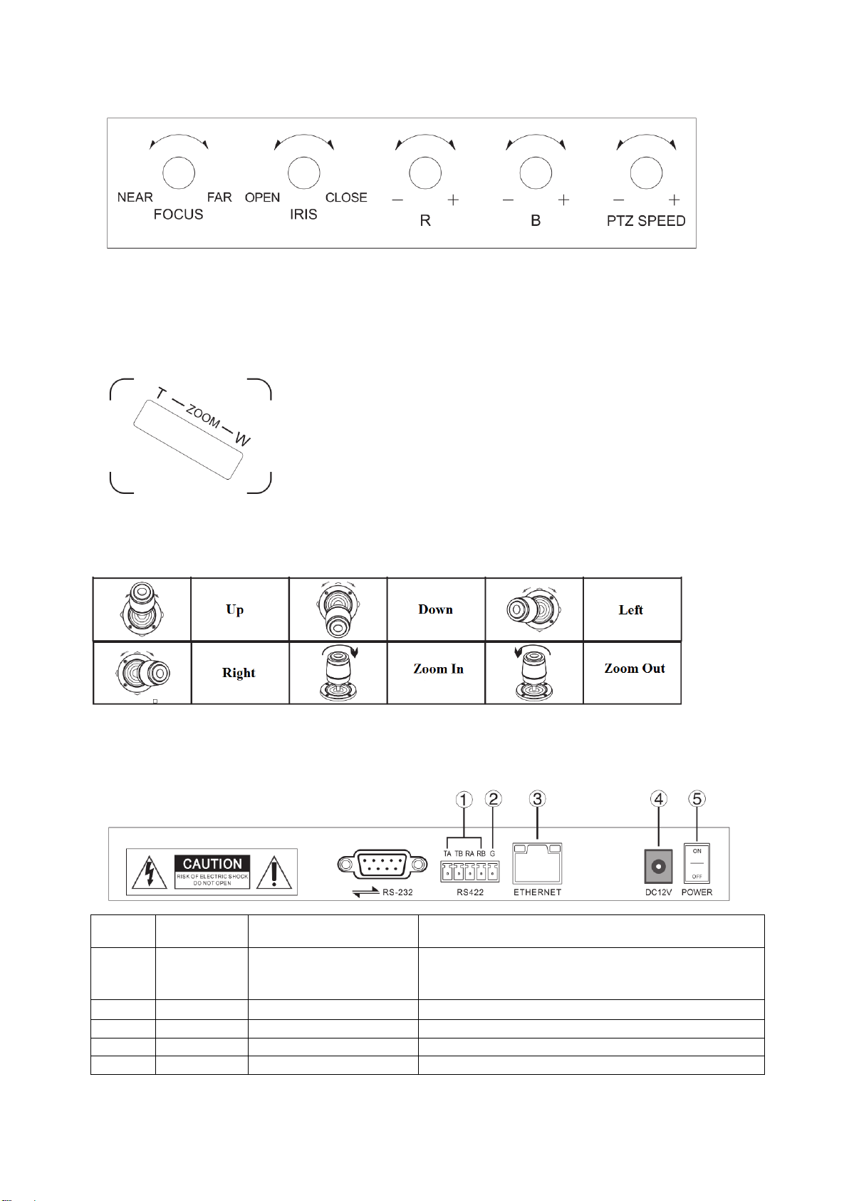
2.2 Rocker Switch and Knobs…………………………………………………….……………………….….….…5
2.3 Joystick Control……………………………………………………………….……………………….….….…5
2.4 Back Panel Interfaces…………………………………………………….…………………………….….….…5
3. Controller Settings………………………….………………………..………..………………………..……..…….6
3.1 Basic Setups…………………..………………………………………………..……………………….…….....6
3.2 VISCA & IP VISCA sharing Mode……………..………………………..……………………………..….……6
3.3 IP VISCA/ ONVIF Mode…………..……………………..…………………………………………..……....…6
3.4 VISCA Mode…………………..………...……………………………………..……………………….…….....6
3.5 PELCO Mode…………………..……..………………………………………..……………………….…….....6
4. Connections and Control.……………………………………….………………… …………….……………..….7
4.1 ONVIF Mode………………………………………..………….……………………..………………..……….7
4.2 IP VISCA Mode…………………………………………….…………………..………………..……….……..7
4.3 VISCA&PELCO Mode……………………………….…………………..……………….……..……….……..7
5. Web Page Configuration…………………...…………….…………………..……………….……..……….……..7
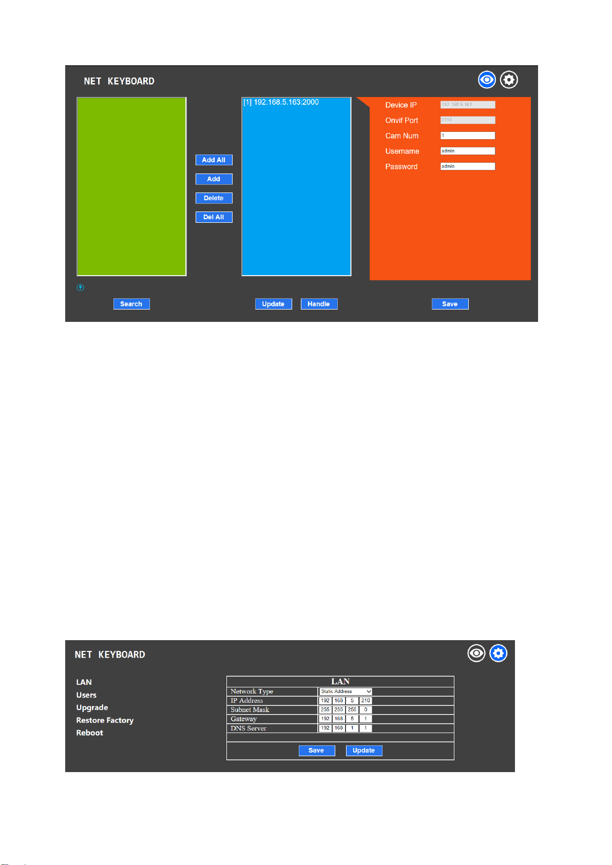
5.1 Home Page……………...…………….…………………..……………………………….……..……….……..7
5.2 LAN Settings……………...…………….…………………..……………….…………….……..……….……..8
5.3 Upgrade……………...………………..…………………..……………………………….……..……….……..9
5.4 Restore Factory……………...………………..…………………..……………………….……..……….……..9
5.5 Reboot………..……...………………..…………………..……………………………….……..……….……..9
6. Maintenance Service Terms ……………………………………………………………………….……...………..9
6.1 Troubleshooting…………..…………..…………………..……………………………….……..……….……..9
6.2 Range of Warranty……………………………………………………………………………………………..10
6.3 Warranty Conditions…………………………………………………………………………………………...10
6.4 Shipping………………………………………………………………………………………………………..10
1

1. Brief Introduction
1.1 Notice
●
Please read this manual thoroughly before use, and keep it handy for future reference.
●
Do not use or store AV-3104IP in an environment where the product is exposed to rainwater,
moisture vapor, salty water, oil, etc.
●
Do not place the controller close to any exothermic object for a long time.
1.2 Functions and Features
●
Users can control the focus, iris, red gain, blue gain, PTZ speed and zoom of the camera.
●
Users can call camera menu, modify camera settings and operate pan, tilt, zoom of the
camera/dome.
●
This keyboard supports multiple protocols including PELCO, VISCA and ONVIF.
●
This keyboard is equipped with a 3D joystick which can control the camera/dome at different
speed.
●
This keyboard is equipped with a large LCD screen displaying Chinese/English menu.
●
Use keyboard buttons to select and define hot keys.
●
Keyboard baud rate: 1200/ 2400/ 4800/ 9600 bps.
●
The keyboard has 4 control modes: 2 x IP control mode (IP VISCA & ONVIF); 2 x analog control
mode (RS422 & RS232).
1.3 Items Included
Please check the items in the package once get the keyboard. Check whether all parts are included
and are in good condition.
●
AV-3104IP Joystick Controller…………………..1 pc
●
DC12V Power Supply…………………………….1 pc
●
User Manual………………….……........………...1 pc
1.4 Wiring Diagram
2

The controller and PTZ camera must be connected within the same LAN. IP addresses need to be
set at the same segment.
For example:
If your camera is set to 192.168.1.123, the keyboard should be set to 192.168.1.xxx. Keep the first
3 sections the same.
The default setting of AV-3104IP controller is obtaining IP address dynamically.
1.5 Technical Specifications
3
Joystick
3D 4-dimension joystick (up, down, left, right, zoom) control
Connection
RS232, RS422, LAN
Display
LCD screen
Power supply
DC 12V1A±10%
Power Consumption
0.6 W Max
Operating Temperature
0°C-50°C
Storage Temperature
-20-70°C
Dimensions
12.6*7*3.9inch (320*180*100mm)

2. Interface Illustrations
2.1 Keyboard Buttons
【AUTO FOCUS】Set the camera to auto focus mode with this button. It will light up when camera is in
manual focus mode.
【AE AUTO】Set the camera to auto aperture mode with this button. It will light up when camera is in
manual aperture mode.
【CAMERA OSD】Call/ exit the camera OSD
【HOME】Camera will return to home position (camera OSD needs to be off). When the camera OSD is
called, the home button is to enter submenu or to confirm.
【F1】~【F2】Users can set different functions to F1 and F2 under VISCA and IP VISCA mode.
【SETUP】View and modify local settings.
【SEARCH】Search for all available devices within the LAN (only under ONVIF Mode)
【INQUIRE】Check added devices
【WBC MODE】Set the camera to auto white balance mode. It will light up when camera is in manual white
balance mode.
【CAM1】~【CAM4】Quickly switch among CAM 1-4 devices.
【PRESET】Press to set preset positions; press and hold to delete preset setting. It needs to work with the
number keys and “enter” button, for setting or deleting presets.
【CALL】Call preset positions, press NUMBER key + ENTER.
【IP】Manually add network devices (only in ONVIF and IP VISCA modes)
【CAM】IP VISCA and ONVIF mode: choose the CAM NUM assigned to a device when adding a new
device. VISCA and PELCO mode: it will switch to the address code when entering a certain address.
NUMBER key + ENTER.
【1】~【9】Can work as direction keys as well, to control pan, tilt, and camera OSD.
【ESC】Return
【ENTER】Confirm
4

2.2 Rocker Switch and Knob
【NEAR】【 FAR】Manually adjust the focal length.
【OPEN】【 CLOSE】Manually adjust the aperture, OPEN(Aperture +)/CLOSE(Aperture -)
【R-】【 R+】Manually adjust the Red Gain
【B-】【 B+】Manually adjust the Blue Gain
【PTZ SPEED-】【 PTZ SPEED+】Adjust PTZ Speed, 1 (Slow)- 8(Fast)
【T-ZOOM-W】Zoom Tele and Zoom Wide.
2.3 Joystick Control
2.4 Back Panel Interfaces
Back panel interface: RS422, RS232, DC-12V, Ethernet, Power Switch
Number
Port
Physical interface
Description
①
RS422
Control Output
(TA, TB, RA, RB)
Connect to RS422 bus of the camera:
TA to camera RA; TB to camera RB;
RA to camera TA; RB to camera TB.
②
Ground
Control line ground (G)
Control signal ground
③
ETHERNET
Ethernet port
Network connection
④
DC-12V
Power input
DC 12V Power input
⑤
POWER
Power switch
Power on/ off
5

3. Controller Setup
3.1 Basic Settings
Move the joystick up and down for 1, 2, and 3 settings;
Move the joystick left and right to turn on and off the button sound;
Confirm with ENTER button.
(1) Network type: dynamic and static
(2) Button sound prompt: on and off
(3) Language setting: Chinese and English
(4) Mode: VISCA, IP VISCA, ONVIF, PELCO
(5) Version information
(6) Restore factory settings
(7) Local IP
3.2 VISCA & IP VISCA Mode
F1: User-defined function for F1 button (under VISCA)
F2: User-defined function for F2 button (under VISCA)
Input custom name → ENTER → Input VISCA command
For example: the command is 8101040702FF, then input 01040702 (0 can NOT be omitted)
3.3 IP VISCA/ ONVIF Mode
Delete an existing device:
Move the joystick up/ down to view devices;
Move the joystick rightward to view the device’s port information;
Move the joystick leftward to view the IP, CAM NUM information;
Press【ENTER】to delete the selected device.
3.4 VISCA Mode
Baud rate setting for a selected camera:
Move the joystick up/ down to select a camera among CAM 1-7;
Press【ENTER】;
Move the joystick left/ right to select a baud rate;
Press【ENTER】to finish setting.
3.5 PELCO Mode
Baud rate setting for a selected camera:
Move the joystick up/ down to select a camera among CAM 1-255;
Press【ENTER】;
Move the joystick left/ right to select a protocol;
Press【ENTER】;
Move the joystick left/ right to select a baud rate;
Press【ENTER】to finish setting.
Default: controller address: 1, control baud rate: 9600, protocol: PELCO-D
6

4. Connections and Control
4.1 ONVIF Mode
To add a new network (LAN) device to the PTZ controller:
•After the controller obtains its IP address, press【SEARCH】button;
•All available ONVIF devices within the LAN will be displayed on the screen when search process is
complete;
•Move the joystick up/ down to select the device, press【ENTER】to confirm;
•Enter the device’s username, password and CAM NUM information;
•Press【ENTER】button to save.
To manually add a device via【IP】button:
•Press【INQUIRE】button to view all the existing devices;
•Move the joystick up/ down to select device (move the joystick rightward to view the information);
•Press【ENTER】to select the target camera. Or use【CAM】button to connect and control.
4.2 IP VISCA Mode
【SEARCH】is not functionable under IP VISCA mode. To manually To manually add a device via 【IP】
button:
•Press【INQUIRE】button to view all the existing devices;
•Move the joystick up/ down to select device (move the joystick rightward to view the information);
•Press【ENTER】to select the target camera. Or use【CAM】button to connect and control.
4.3 VISCA & PELCO Mode
Set the address number (CAM NUM) and baud rate accordingly:
Move the joystick up/ down to select a camera among CAM 1-7 (VISCA)/ 1-255(Pelco);
Press【ENTER】;
Move the joystick left/ right to select a protocol;
Press【ENTER】;
Move the joystick left/ right to select a baud rate;
Press【ENTER】to finish setting.
5. Web Page Configuration
5.1 Home Page
Connect the controller and PC via an Ethernet cable within the same LAN. Enter the controller’s IP address
into the browser.
Default username: admin; password: leave it empty
Home page is shown as below:
7

There’re 3 sections on the Home page: Search Device List (green); Added Device List (blue) or Manually
Add (yellow); Device Details (orange).
•Click【Search】button to find ONVIF devices within the LAN, which will appear in the green area
automatically.
•To add a device, select the device in the "Search Device List", and click 【Add】. Press “Ctrl”for
multiple selection.
•To delete a device, select the device in the "Added Device List", and click【Delete】. Press "Ctrl" for
multiple selection.
•After adding a device successfully, click on the IP address in the "Added Device List" to edit the
account/ port information of the device.
•After modification of any list, click【Save】to save changes.
* Any modification to the configuration on home page needs to be saved before leaving the page; otherwise
the modification is invalid.
5.2 LAN Settings
Under LAN Settings, users can modify the way to access the IP address of the current device and change port
parameters. The page is shown as below:
8

Static address: When users need to manually set the network, change the Network Type to Static Address.
Input the network segment information.
Dynamic address (default): the controller will automatically acquire IP address from the router.
5.3 Upgrade
The upgrade function is applied when maintenance or update is needed.
Choose the upgrade file and click【Start】to initial the process. The controller will auto reboot after updating.
* Do not operate the controller during the upgrade process. Do not power off or disconnect from network.
5.4 Restore Factory
Restore the controller to factory default settings when unexpected failure occurs due to incorrect modifications.
Please use it with caution. Do not restore to default if the controller is working.
5.5 Reboot
For maintenance purpose, reboot the controller if the controller has been on for a long time.
6. Maintenance Service Terms
6.1 Troubleshooting
1. What is the function of CAM NUM when add a network device?
CAM NUM will be assigned to and associated with the currently added IP device and port.
2. How to enter user name, password and custom keys of F1/ F2.
For instance, to enter letter “C”, simply press number key【2】three times until the letter shows on the screen.
3. How to enter IP address?
This camera controller doesn't have "." button. So, the IP address is entered with 4 segments.
Take 192.168.0.1 as an example, the cursor will automatically jump to the next segment once 3 digits are
entered; if there’re less than 3 digits in one segment, you’ll have to move the joystick rightward to go to the
next segment.
4. How to delete a digit?
Move the joystick leftward to delete the input information.
5. IP VISCA and ONVIF mode:
If you see【Visca !】/【Onvif !】, the IP address displayed on the screen should be the controller’s IP address.
If you see 【Visca :】/ 【Onvif :】, the IP address displayed on the screen is the connected device’s IP
address.
9

6.2 Range of Warranty
●
AViPAS warrants its new product against defects in materials and workmanship for a period of ONE (1) YEAR
from the date of original invoice.
●
Within three months after the 1-year warranty, if the product is noticed to have the same malfunction as before
the warranty ends, it will obtain free maintenance service.
●
This warranty does NOT cover problems or damage resulting from, but not limited to, any of the following: any
accident, disassembly, or misapplication; any improper operation that is not in accordance with the supplied product
instructions; any other cause which does not relate to a product defect in materials or workmanship.
●
Please avoid stress, vibration or soakage during transport, storage and installation. Problems or damage resulting
from the above are NOT covered by warranty.
●
Please remain the way of fission package and our original package for transport. Any damage resulting from
integrated package or customer package are NOT covered by warranty.
●
This warranty does NOT cover any problem or damage resulting from unauthorized repair or disassembly.
●
Our company does offer repair services to out-of-warranty products. Please notice that service fees will be
charged.
●
For the defected products: if it's still under warranty, please fill out the warranty form with all the information
needed, describing the problems in detail. Customers may be asked to furnish proof of ownership and date of
purchase by showing the sales receipt/purchase invoice/warranty card.
●
We are not responsible for the damage or loss caused by specific usage or applications. Any compensation made
by the company regarding breach of contract, negligence or infringement won't exceed the amount of the product.
The factory won't bear any responsibility for special, unexpected or continue damage caused by any other reasons.
●
Our company has the final right of explanation for the above terms.
6.3 Warranty Conditions
●
Customers may be asked to send the warranty card and a detailed description of the problem together with the
product for repair.
6.4 Shipping
●
If the product needs to be sent back to the manufacturer for repair, the customer can send it back to the
manufacturer directly or through the supplier. If sending back to the manufacturer directly, please contact us first to
speed up the process. Our company is only responsible for the one-way shipping fee from the manufacturer to
customer after repair or maintenance.
10

Copyright Notice
All contents of this manual, whose copyright belongs to our Corporation cannot be cloned, copied or translated without
the permission of the company. Product specifications and information which were referred to in this document are for
reference only. We may alter the content at any time and without prior notice.
Ver 2019-7-11 (EN)
Contact Details:
AViPAS, Inc.
Address: 4320 Stevens Creek Blvd. Suite 227
San Jose, CA95129
Phone: 1-844-228-4727
Fax: (408) 228-8438
Email: [email protected]
Website: www.avipas.com

Table of contents
Other Avipas Controllers manuals