manuals.online logo
Brands
  1. Home
  2. •
  3. Brands
  4. •
  5. AviPro Aicraft, Ltd.
  6. •
  7. Tools
  8. •
  9. AviPro Aicraft, Ltd. Bearhawk N33RB User manual

AviPro Aicraft, Ltd. Bearhawk N33RB User manual

Popular Tools manuals by other brands

AGI Westfield MKX16 Assembly manual

AGI

AGI Westfield MKX16 Assembly manual

GYS HAND-DUCTION 056923 Translation of the original instructions

GYS

GYS HAND-DUCTION 056923 Translation of the original instructions

Grizzly H7583 instruction manual

Grizzly

Grizzly H7583 instruction manual

Sealey VS0462.V2 instructions

Sealey

Sealey VS0462.V2 instructions

Makita HR2650 instruction manual

Makita

Makita HR2650 instruction manual

Forza 1100H Series manual

Forza

Forza 1100H Series manual

Aventics EBS-PI operating instructions

Aventics

Aventics EBS-PI operating instructions

Martor SECUNORM 175 quick start guide

Martor

Martor SECUNORM 175 quick start guide

jbc N4473 instruction manual

jbc

jbc N4473 instruction manual

FEINMETALL FZWZ-SET-001 quick start guide

FEINMETALL

FEINMETALL FZWZ-SET-001 quick start guide

Worx Professional Sonicrafter WU676 Original instructions

Worx Professional

Worx Professional Sonicrafter WU676 Original instructions

Gage Bilt GB713SH Original instructions

Gage Bilt

Gage Bilt GB713SH Original instructions

Hilti DX 9-ENP Original operating instructions

Hilti

Hilti DX 9-ENP Original operating instructions

norbar NORTRONIC 34399 Operator's manual

norbar

norbar NORTRONIC 34399 Operator's manual

BGS technic 8578 manual

BGS technic

BGS technic 8578 manual

axing BWZ 5-02 Operation instructions

axing

axing BWZ 5-02 Operation instructions

Makita DHR241 instruction manual

Makita

Makita DHR241 instruction manual

Motor Guard JMB-1250 instructions

Motor Guard

Motor Guard JMB-1250 instructions

manuals.online logo
manuals.online logoBrands
  • About & Mission
  • Contact us
  • Privacy Policy
  • Terms and Conditions

Copyright 2025 Manuals.Online. All Rights Reserved.

2
What To Do And When to Do It
Note: this is a very rough guide that outlines
the major steps to be taken and the order in which
they should be taken. This is not cast in concrete,
but is a suggestion.
1-Remove pop rivets and inventory parts shipped
inside wings
2-Prepare table or resting place for wings
3-Remove wings from crate
4-Check all pre-installed bolts for correct length
and torque .
5-Install stiffener at lower back edge of wing
skins, fla area (if not already in place by factory)
6-Install flap actuation system, flap springs,
torque tube, etc.
7-Install aileron bellcranks, pulleys and actuation
system
8-Run aileron cables
9-Install back ribs at tip/root, root back skin.
10-Position wings on fuselage
11-Set incidence, drill fuselage and wing fittings
12-Set dihedral
13-trim and drill struts
14-Remove wings
15-Install flaps and ailerons (then remove)
16-Finish flaps and ailerons (can be done later),
except trailing edge.
17-Install main fuel tanks including cutting hole
for filler neck
18-Install tank bay stiffeners (optional)
19-Cut hole in bottom skins for aux tanks (if
applicable)
20-Install aux tank straps, pump and plumbing
21-Fabricate aux tank cover, install nut plates
22-Run conduit for aux tank pump and nav light
wiring
23-Install pitot system
24-Install inspection door frames and nut plates
25-Rivet top wing skins down
26-Back-rivet tank bay stiffeners into place
27-Install aileron well pocket rib skins
28-Install main tank covers
29-Install wing tips
30-Finish flap, aileron trailing edges
31-Install wings
32-Finish running aileron/flap cables
33-Fabricate wing-to-fuselage/windshield fair-
ings.
Some Thoughts on Working Aluminum
Compared to the fuselage, the wings are a
piece of cake in terms of the amount of time they
Wings: Getting Started
When the wings come to you, after you’ve drilled out the pop rivets installed for shipping, this is what you have: nearly complet -
ed wings needing only the systems installed and the top sheet riveted down between the spars. You’ll have to come up with a
system of curling the sheets back so you can work on the inside of the wings. This builder used 1 x 2 wood with finishing nails
in the end that will fit through the rivet holes. Others use PVC pipe or long pieces of wood suspended via wire to the bench.
3
will take to complete. However, because you’re
working with aluminum, it’s necessary you make a
special effort to be as careful as possible to avoid
scratches, sharp edges, etc. Where steel is quite tol-
erant of such things, aluminum isn’t. Each scratch
that can be felt with a fingernail needs to be
Scotchbrited out because it is a stress riser and the
possible starting point for a fatigue crack later in
life. This isn’t meant to scare anyone but to point
out the necessity of taking special precautions to
protect the material, especially the outside skins.
The biggest sources of scratching on alu-
minum structures is accidentally laying it on some-
thing seemingly as harmless as drill shavings or a
stray rivet. The best way to protect against that is to
cover your work surface with deep pile (not shag)
carpet and vacuum it periodically.
Work Tables
The hot ticket for building wing tables is to
make them from the shipping crates. Turn the crates
upside down on a set of saw horses (bolt or clamp
them down) OR, if you’re a welder, use the steel
from the crate top to build legs for the crates.
If you want, you can just take the foam out
of the crates and use it to pad the top or screw some
plywood onto the frame. When you’re finished
with the wings, you can use the steel in the wing
tables to build racks from which to hang the bazil-
lion small parts you’ll have to paint.
The table have to have a hole in the middle
to accept the strut attach straps that stick out of the
bottom of the wings
Unpacking the Wings
Don’t try to open the crates by yourself: the
tops are too awkward and it would be really easy to
lose control for a second and dent something. The
tops aren’t even remotely heavy (25-30 pounds),
but have an extra set of hands ready to help.
The flaps and ailerons are packed on top of
the top wing and covered with foam. Because the
foam is so light, don’t attempt to unpack the wings
in a wind because it’ll pick up the big pieces of
foam even as you try to get them out of the crate.
From this point on, remember that every-
thing in the crate is super easy to damage, so treat
the contents as if they are eggs.
When it comes time to lift the wings out of
the crate, two people can easily handle the wings
but be paranoid about the way the vertical parts of
the crate are sticking up just waiting for you to slip
and drop the wing on them.
Each piece of wing skin has a couple of alu-
minum pop rivets that need to be drilled out. USE
A#40 DRILL, NOT A1/8”, to remove them
because the rivet holes are for AN3 rivets. You
don’t have to drill all the way through. Just drill
enough to remove the head and, if they start to spin,
grab the butt with a pair of pliers. They should
come out very easily, when pushed with a punch.
Once the skins are free, remove and inven-
tory all the small parts packed in the gas tank bay.
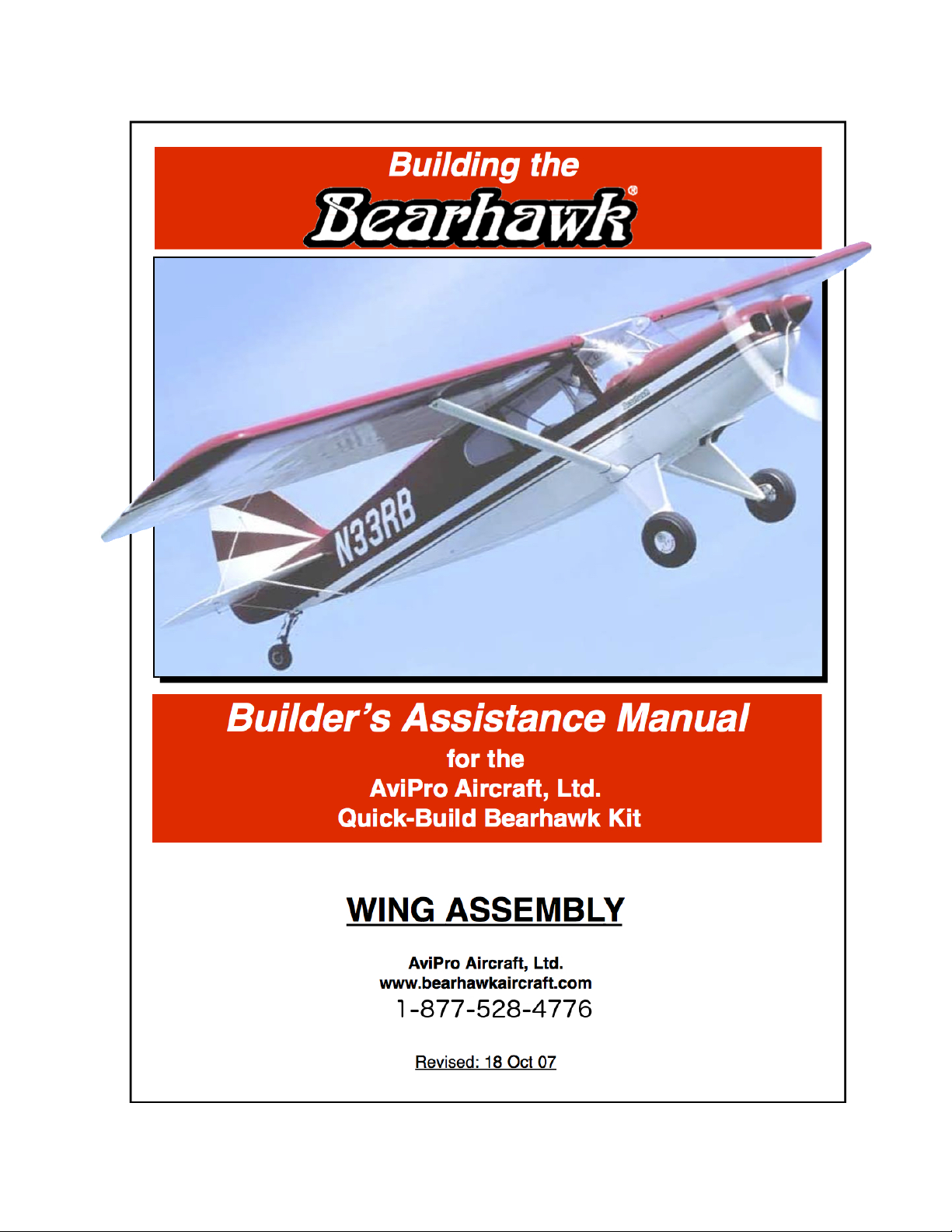
Curling the Skins Back
To work inside the wings you’ll need a
method of curling the skins back and holding them
there in a solid manner.The opening picture shows
pieces of wood with finishing nails in them.
Another way to do it is by running boards ( 2 x 3)
or PVC pipe spanwise under the skins and tethering
them to the ceiling or the back side of the work
bench so they can’t move.
It’s important when setting up your skin
restraint system that it be infallible because should
one skin break free and try to come down, it can put
dings in the edge of the sheets where they overlap.
IMPORTANT: CHECK BOLTS
Before doing another thing, go through the
wing and check the bolts that were installed at the
factory. They should not be considered “ready to
fly” until you have checked each one for being the
right size and length, the requisite three threads are
free of the nut, that the nut is the appropriate type
AND THE BOLT HAS BEEN PROPERLY
TORQUED.
Aset of easily made dollies for your wing crate makes them
much easier to handle. An alternative are Harbor Freight fur -
niture dollies.
On Building A Wing Rotisserie
Although a rotisserie is a long way from
being necessary, we thought we’d share what one
builder fabricated to make his life easier, and it
would indeed do that. Aday with a hacksaw and
MIG welder, gives you a way of handling your
wings that can’t be beat and allows one man to do
many tasks, including turning the wings over, that
would require another body to help. This is an
excellent use for one of your crate tops.
Bolts Nuts
Used
Max
Torque
Nuts
Used
Max
Torque
AN365/
AN310
Inch-lb. AN364/
AN320
Inch-lb.
10-32
(3/16)
20-25 40 12-15 25
1/4-28 50-70 100 30-40 80
5/16-24 100-140 225 60-85 140
3/8-24 160-190 390 95-110 240
7/16-20 450-500 840 270-300 500
The wings don’t weigh very much (150 pounds), but they are
not only awkward but very easily damaged. Plus, you’re
always wishing you could get at the other side.
The construction uses 1” x 1/16 tubing as is used in security
gates and can be found everywhere. Better yet, there’s
enough steel in the top of one of your crates to build the dolly.
Alocking mechanism doesn’t get any simpler than this. The
wing just lays in the pivot and the locking knob screws through
a nut welded to the frame.
When it comes time to paint the wings, a couple dollies like
this would guarantee a better paint job because you would
always be painting down at an angle with no vertical passes.
5
There are any number of places you could
start on the wings, but to get you into the aluminum
process with a minimum of hassle, the stiffener that
lays in the open area behind the rear spar in the flap
bay is a good place to start, although it has been
done by the factory in later kits.
The goal here is to attach the stiffener and
have the back edge of the sheet metal remain per-
fectly straight. The reason we mention this is
because, when a rivet is driven, it expands the hole
very slightly and, unless you plan ahead, it’s possi-
ble to get distortion in the skin. It will manifest
itself as a wavy or slightly recurved skin. However,
with just a little fore planning, this can easily be
avoided.
There are actually two stiffeners, one top
and one bottom and they overlap the flange of the
rear spar and are flush, or very close to being flush,
with the trailing edge of the skin.
Wings have been supplied in several differ-
ent degrees of completion in this area, as the kits
were improved. The different configurations
include:
1. Bottom skin and spar are drilled and dim-
pled but the stiffener is not.
2. Bottom stiffener is completely installed
and finish riveted (all later kits)
3. Top skin and spar flange are drilled and
dimpled but the line of holes behind the spar is nei-
ther drilled nor dimpled and the top stiffener is
NOT drilled or dimpled for any of the rivets so it
needs two lines of holes drilled and dimpled.
4. Top skin and flange have both lines of
holes drilled and dimpled and the stiffener has
matching holes and dimples
Drilling the Stiffener (if it isn’t drilled)
In most of these cases, the stiffener has
no holes in it, but both the spar and the skin are
drilled and dimpled but an additional line of
holes and dimples needs to be made between the
spar flange and the edge of the skin. Use the
front row of holes as guides to drill the stiffener
and hold it in place while drilling the rear holes.
To visualize what you’re trying to do, look at
Drawing No. 9.
You can drill the holes either direction,
meaning have the wing right side up and drill from
the bottom up (with the edge hanging off the work
table) OR turn the wing over and drill down. Most
people are more comfortable drilling down, but
that’s up to you.
Clamp the Stiffener in Place
What follows is a general instruction of
how to drill and install the stiffener. It is assumed
the stiffener has no factory-drilled holes in it, nor is
the second, rear-most line of rivet holes drilled in
the skin. In most later kits the stiffener and all holes
in the top skin and spar flange will have been
drilled and dimpled. The bottom stiffener may also
be finish riveted. If that’s the case, much of this can
be skipped.
The first step is to position the stiffener so
it’s flush with the trailing edge (or close to it) but
the front edge overlaps the holes in the spar flange
enough to give a distance from the center of the
holes to the edge of the stiffener of at least twice the
diameter of the rivet or 3/16”.
Once you have a couple of holes drilled you
can hold the stiffener in place with clecos and it
won’t move while you drill the other holes. HOW-
EVER, getting those first holes in without the stiff-
ener moving takes a little forethought (doesn’t
everything?): the stiffener must be clamped in posi-
tion until you have at least four holes drilled in it to
accept clecos. They should be at each end and
spaced through the middle.
To clamp the stiffener in place the best solu-
The small stiffener at the back of the bottom wing skin isn’t difficult
to install but paying attention to a few details, especially squeezing
rivets through a thick piece of aluminum angle, will improve the
Wings: Installing Flap Skin Stiffener
6
tion is about half a dozen side-grip clecos. Or pad a
couple pair of Visegrips or small C-clamps with
masking tap to prevent marking the aluminum and
clamp the stiffener in place.
Drilling the Holes
Make a back-up block out of a six-inch
piece of two-by-four or something similar that will
be held against the stiffener and drilled into. This
will keep the stiffener from flexing while being
drilled.
You’ll use the existing holes in the skin and
spar flange to drill the front holes in the stiffener.
Drill a couple of holes in the middle of the stiffen-
er. Put clecos in the holes, then space out three
more holes evenly spaced down the length of the
stiffener. Make sure none of the clamps have
slipped.
Once you have those clecos in place, the
stiffener definitely isn’t going to go anywhere so go
ahead and drill the rest of the holes.
Don’t start at one end and work to the other
end as the stiffener will creep. Start at the middle
and work our way out.
Once the holes are drilled, debur them and,
if they aren’t already dimpled, dimple using a
squeezer, but don’t squeeze too hard or you’ll get
distortion. .
Riveting the Stiffener.
While it is entirely possible to simply drop
the rivets into the holes and whack away with a
squeezer, chances are you won’t be satisfied with
the result because it’s hard to keep the trailing edge
straight and from recurving: the rivets expand and
push the aluminum around. However, there is a
way to prevent that.
Buy a heavy, extruded aluminum angle
(1/4” thick, 2” or so wide) and squeeze the rivets
using the angle as both a straight edge and as an
interface between the squeezer the heads of the riv-
ets.
The procedure is as follows:
1. Drop all the rivets into the holes.
2. Position the stiffener over the rivets.
3. Lay the angle down over the rivets.
4. Clamp the angle and stiffener together.
Make sure it’s clamped tight in about a dozen
places.
5. Adjust your squeezer to properly com-
press the rivet by squeezing the angle against the
rivets.
6. Don’t rivet in a straight line. Do several
in the middle, the end rivets, then every third one
starting in the middle and working out. Then come
back to the middle and, working your way out, fin-
ish the rest of them. Using this technique you won’t
drive the expansion all one direction and will limit
distortion.
Mis-matched Stiffener/Rib Intersection.
Afew wings were shipped with the lower
stiffener riveted in place but it is about three-quar-
ters of an inch too long and has to be trimmed to let
the flap bay root rib fall in place. Just drill out a
couple of rivets and cut three-quarters of an inch off
the inboard end of the stiffener. A Dremel tool is the
easiest way to cut it. Protect the wing skin beneath
by inserting a piece of aluminum scrap.
The stiffener at the bottom, front of the flap bay is finished dif -
ferently depending on the vintage of AviPro kit you’re building.
However, when finished, they all look like this.
Afew wings were produced in which the stiffener was too long
and it interferes with the root rib. Trim off about 3/4” with a
Dremel tool being careful not to cut the skin. Protect it with
scrap aluminum.
7
Understand the Concept
Before doing anything on the flaps system
pull out drawings No. 12 and No. 14. They will
give you a good familiarity of how the different
parts relate to one another and how they work.
Also, study the photos in this section. They will
clarify any questions.
The flap system is quite simple in that it is
nothing but a torque tube coming in from the root
with an actuating arm at each end. At the root it is
attached to a cable and at the other end a push rod
is attached to the middle flap hinge and pushes the
flap out. The flaps are held in the up position by the
long springs included in the later kits or available
from AviPro for the older kits.
The procedures we’ll use to install the sys-
tem include:
1. Install torque tube
2. temporarily slide actuating arms into
position on the torque tube
3. Position and drill outboard actuating arm.
4. Install inboard actuating arm, but don’t
drill.
5. Install springs
Install Torque Tube
The torque tube slides through
the steel stand-off bushng at the root and
through a similar bearing stand-off at the
mid-wing cross member. Before sliding
the outboard end into the bearing note
that one of the outboard arms has to be
slid in place first (see photo).
Because both the torque tube and
the bearings have been painted, it’s a
good idea to remove the paint from both
the inside of the bearings and the area on
the torque tube where the bearings will
ride. This not only makes it much easier
to slide the tube into position but greas-
ing the metal-to-metal contact makes for
much smoother operation.
Drilling the Actuating Arms
Each torque tube has three actu-
ating arms, one at the root and two that
perform as one and clamp the push rod
between them (see pictures). Ahole needs to be
drilled through the base of the arms and through the
torque tube to accept AN3 (3/16” bolt) to stop the
arms from rotating on the torque tube..
It is best if these bolts have a snug fit, so
rather than drilling with a 3/16 bit, drill with an
11/64” and ream to size to eliminate any possibili-
ty of slop in the holes.
On the outboard arms, first bolt the short
The actuating pushrod is trapped by two actuating arms, both of which have
a spring (not shown) going forward and holding the flaps up.The torque tube
(going to the left) must be drilled to hold the arms
Wings: Installing the Flap Actuation System
Paint must be removed from inside the arms and off the torque
tube to ease getting the actuating arms on the tube. Note how
the pushrod is sandwiched between two actuating arms.
8
flap push rod between them to hold them in align-
ment. Then clamp the top end of the push rod
where it bolts to the arms down to the crossmember
tube to keep it from moving while drilling it.
The root actuating arms have to be mount-
ed at a specific angle on the torque tube to give the
flap cables the most efficient angle for pulling.
With the outboard actuating arms still
clamped against the fore and aft tubing crossmem-
ber, position the inboard arm as per Drawing No.
14.
Because there is limited room between the
fuselage and the wing root, it is essential that the
flap actuating arm be centered in that gap. For that
reason, it’s advisable to drill the hole through the
actuating arm and torque tube AFTER the wings
are on the airplane to ensure no interference occurs.
IT S RECOMMENDED THAT THE OUTBOARD
ACTUATING ARMS BE DRILLED WITH THE
WINGS ON THE AIRPLANE.
Come in from the bottom (or turn the wing
over) and center punch where you’ll drill the hole
in the arms. Then drill one arm with a fresh 1/8” bit
(make it fresh, so it cuts cleanly and easily). Using
that as a guide, drill with the 11/64” and ream. Then
put a bolt in place to keep it lined up.
Do 1/2 of the outboard arms at a time, so
one of them is finished and bolted in place, which
will hold the other one in position and eliminate
minor mis-alignments and wallowed-out holes.
These will be bolted with Nyloc nuts.
If you want, you can install the flap springs
now, which will help hold everything under tension
and keep everything from moving.
ANote About Drilling
The back side of every hole you drill is
bound to have at least a certain amount of burr
standing up. The burr will be less if you use a sharp
bit and don’t push too hard, but you’ll still get a
burr. Your life will be much easier later on, if you
file off every burr you can reach, including those
inside the actuating arms. Not only does this pro-
duce a nicer looking unit with fewer stress risers
but it makes putting the torque tube in and out
much easier. This is where a Dremel tool with a lit-
tle sanding drum on it would come in handy for
those inside burrs.
The Flap Actuating Cable
Later, after you put the wings back on the
airplane semi-permanently and position the actuat-
ing arms and drill the mount bolt, you’re ready to
attach the actuating cable. The flap arm was deliv-
ered with a 3/16” hole (AN3) hole, however you
use a 1/4” shackle rather than a 3/16” shackle to
give a longer distance at the arm, which increases
cable clearance from some structure.
A3/16” (AN3) bolt will be sloppy in the
shackle so bush it down with short pieces of 1/4 x
.028” tubing. If you can’t find that size tubing, con-
tact AviPro. The only charge is for shipping. Later
kits have six inches of the tubing supplied.
The actuating arm at the inside end of the torque tube uses a
1/4” shackle for connecting with the flap cable and it is bushed
down to 3/16” with 1/4” x .028 tubing.
Sand the paint off the inside of the pivot bushing and the tube
and it’ll be easier to insert it and it will work much easier.
9
at th
The Concept of the Aileron System
The aileron control system has no push rods
in it other than a short one that transfers motion
from the bellcrank in the wings to the aileron itself.
Otherwise everything happens as part of a “closed
loop” cable system.
By closed loop we mean there is a gigantic
loop of cable that essentially goes from one wing to
the other with the control stick spliced into one leg
of it and imparting motion. The cables, which are
all 1/8” stainless) attach to the end of the control
stick push rods, run up inside the lift strut into the
wing, around a pulley at the top of the strut that
routes the cable back to the aileron bellcrank, then
back toward the fuselage where it continues all the
way across the inside top of the fuselage and into
the other wing where it makes a similar “U” turn.
The cables are joined in the top of the fuselage by
a turnbuckle that allows adjustment of the tension.
Adjustment of the aileron neutral position is
accomplished by adjusting the push rod that con-
nects the bell crank to the aileron. It’s an extremely
simple system and easy to install and maintain.
Notes About Working With Cable
First, get a cable cutter.Aircraft cable is
extremely hard and difficult to cut. It can be cut
with a cold chisel on an anvil but a dedicated cable
cutter does a much better job and you’re going to
be cutting a lot of cable in this airplane.
Also, get a Nicopress machine AND a
go/no-go gauge. The gizmo that compresses the
Nicopresses isn’t really a machine and can be either
a pliers-like crimper or a set of steel blocks
squeezed together by tightening bolts. Either way
you want to get a go-no-go gauge and check each
and every Nicopress.Go to the Bingelis books and
read and re-read what he has to say about setting
Nicopresses. They aren’t difficult to set, but many
parts of the control and flap system in this airplane
depend on Nicopresses to work so we don’t want
one to slip anywhere in any of the systems.USE
ONLY AIRCRAFT NICOPRESS SLEEVES NOT
THOSE FOUND AT A HARDWARE STORE.
Right wing, looking forward. The cable at the front goes down
through the strut. Just off the bottom of the picture, another
cable goes to the left and across the top of the airplane.
Wings: Installing the Aileron Actuation System
Front aileron pulley . Note the cable guard.
Aileron bellcrank. Here you can clearly see the cable at the
bottom of the picture that is connected to the other wing. At the
lower right you can see the fuel pump and the transfer line.
10
Cable Guards
It’s not unheard of for a control or flap cable
in an airplane, any airplane, to run off the pulley.
For that reason, every pulley in the control/flap sys-
tem should have a cable guard on it unless, as with
the three in the belly of the Bearhawk, the structure
stops a cable from walking over the edge of the pul-
ley. These guards are available from a number of
sources including AviPro.
Cable guards aren’t supposed to turn with
the pulley.They are supposed to be fixed. Since
they are attached to the pulley by the pivot bolt,
they want to pivot too. For that reason, they must
be fixed to something that doesn’t move or at least
have a tab that contacts structure and stops rotation.
See the photos.
Install the Bellcrank
The aileron bellcrank pivots on a bolt that
goes through the fore-and-aft steel support tube
that’s bolted between the two spars. This bolt goes
through two KP bearings, one inserted into the top
of the bellcrank and one that goes into the bottom.
They do not come with the kit but are part of the
Wicks hardware kit. They are meant to be inserted
into the pivot tube of the bellcrank where they rest
against the lip formed by a short piece of tubing
that’s inside the pivot tube. You may have to sand a
little paint out of the inside of the tube to get them
to slip in. They should have a snug fit, as they
aren’t supposed to turn in the bellcrank.
The bellcrank pivots in such a way that one
of its arms goes through a hole in the rib next to it.
In a few early kits there was a little interference
there so you may have to open up the odd-shaped
hole right there. If you do trim it, take as little away
as possible and make sure the edges are filed and
sanded smooth. At the same time, make absolutely
certain there is plenty of clearance: the last thing
you need is the aileron bellcrank hanging up.
The bolts used everywherein the control
system, including the pivot bolts for the bellcrank
and those attaching the cables to it, are drilled bolts
using castellated nuts and cotter pins.
Routing the Cables
When routing the aileron cables through the
wing you always have to be aware of any clearance
issues with structure or components.
Where the cable comes off the front pulley
and goes down inside the lift strut, it’s possible you
might have to file a little off of the edge of the strut
to get clearance. This isn’t critical other than mak-
ing sure the bottom of any notch you cut is well
rounded and smooth. Sand it with 320 grit paper
and slightly round the edges to remove stress risers.
The hole in the wing skin is approximately
two inches aft of the rear steel strap strut attach and
5/8’ outboard of the main strut/wing attach bolt.
Again, smooth the edges.
Watch for Cable clearance
Where the cables come off the bellcrank
and go down the wing and toward the fuselage
early kits have a number of places where ribs need
clearance notches cut or holes elongated.
Specifically, on ribs #7 and 8 the holes may need to
be ovaled out. You want the cable to pass1/4” to
3/8” above the flap mechanism support tube that
runs between the two spars. Any enlargement of the
holes should leave at least 1/4” between the hole
and the large lightening hole. If it is closer than
that, make the hole a "slot" off the big lightening
hole. Again, make it a smooth notch that’s shaped
like a finger tip.
Attaching the Cables
The cable that comes from the front of the
bellcrank and down the lift strut should be attached
with a turnbuckle (AN130-32S w 1/4 x .028 bush-
ing)) to allow adjustments on that part of the cable
circuit.
The cable that comes off the back of the
bellcrank toward the fuselage can be attached with
a shackle and thimble. Aturnbuckle (AN140-22S)
will be inserted in that cable in the middle of the
cabin roof where it transitions over to the other
wing.You’ll be attaching 1/8” cable with thimbles
(AN100-4) that are each Nicopressed (Wicks #428-
4-VM)).
Hole in the bottom of the wing where the cable comes out.