manuals.online logo
Brands
  1. Home
  2. •
  3. Brands
  4. •
  5. Sony
  6. •
  7. Conference System
  8. •
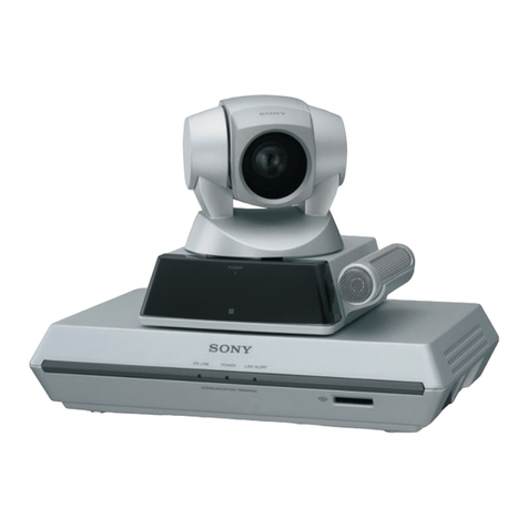
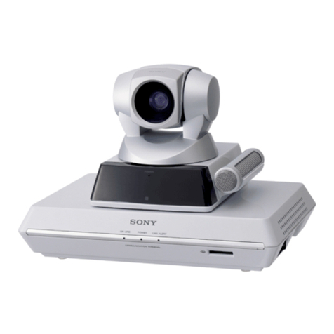
  9. Sony IPELA PCS-G70 User manual

Sony IPELA PCS-G70 User manual

3-869-384-14 (1)
© 2005 Sony Corporation Printed in Japan
Video Communication System PCS-G70/G70P
Connection Sheet (LAN Connection)
System Setup
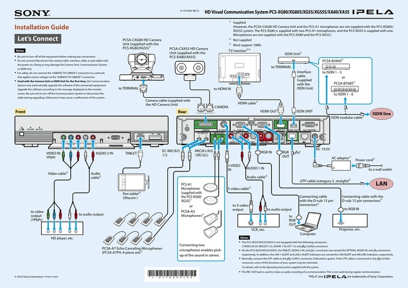
3Connect the camera.
Connect the Camera Unit and Communication
Terminal using the supplied camera cable.
4Connect the Data Solution Box.
Connect the Data Solution Box and Communication Terminal
using the cable supplied with the Data Solution Box.
5Connect the LAN cable.
Connect the Communication Terminal to a
LAN using a LAN cable (not supplied).
1TV monitor** 3Camera Unit
Communication Terminal
PCS-PG70/PG70P
4Data Solution Box
PCSA-DSB1S**
5LAN cable**
6AC adaptor
Power cord*
LAN
1Connect the TV monitor.
Connect the TV monitor and Communication Terminal
using the supplied audio cable and S-video cable.
• When connecting a second or third
monitor, use the VIDEO OUT
MONITOR 2 or the RGB OUT
connector on the Communication
Terminal, or the RGB OUT
connector on the Data Solution
Box. For details, refer to the
Operating Instructions.
• The AUDIO OUT (MIXED) jack is
used to make an audio recording of
a conference. This is not used
during regular conferences.
When using only one camera, connect it to the
MAIN CAMERA connector. A second camera can
be connected to the SUB CAMERA connector.
6Connect the AC adaptor.
Connect the supplied AC adaptor to the
Communication Terminal, and then plug the
power cord into a wall outlet.
AC adaptor*
to a wall outlet (120V AC)
Power cord*
PCSA-CG70/CG70P**
Let’s connect
Used with the Data Solution Box for the first time, the
Communication Terminal may automatically upgrade the software of
the Data Solution Box. While the upgrading message is displayed on
the monitor screen, be sure not to turn off the Communication
Terminal. Doing so may cause malfunction of the system.
Interface cable (supplied with
the PCSA-DSB1S)
Camera cable
(supplied with the
Camera Unit)
UTP cable
(category 5, straight)**
*supplied
** not supplied
•Be sure to turn off all the equipment
before making any connections.
•Do not connect/disconnect the camera
cable with the power on. Doing so may
damage the Camera Unit or
Communication Terminal.
*supplied
Communication
Terminal
** not supplied * supplied
Notes
S-VIDEO INAUDIO IN
L R
S-video cable*Audio cable*
TV monitor
Communication
Terminal
For safety, do not connect the 100BASE-TX/10BASE-T
connector to a network that applies an excess voltage
via the 100BASE-TX/10BASE-T connector.
“IPELA” and are trademarks of Sony Corporation.
2Microphone
PCS-A1**
Communication
Terminal
Communication
Terminal
to LAN
Data Solution Box
Communication
Terminal
Camera Unit
2Connect the
microphone.
Connect the microphone cable
to Communication Terminal.
Communication
Terminal
Microphone
• For connection examples using the Remote Control
Receiver and Plug adaptor, refer to the Operating
Instructions on the supplied CD-ROM.
•Both the Remote Control Receiver and the Camera Unit
can receive signals from the Remote Controller. When
both are connected at the same time, the Remote Control
Receiver receives the Remote Controller signals.
Plug adaptor*
Remote Control
Receiver*
VGP-AC19V45 or
VGP-AC19V15*
Connection Sheet (ISDN Connection)
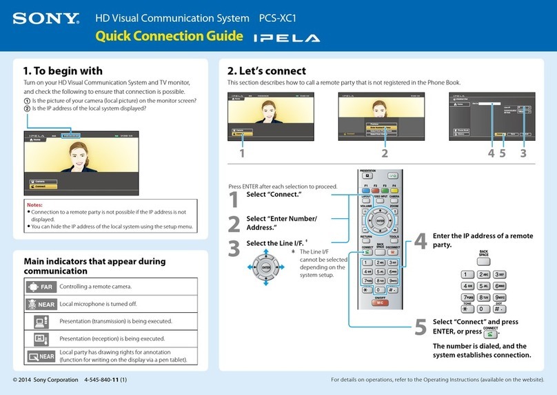
3Connect the camera.
Connect the Camera Unit and
Communication Terminal using the
supplied camera cable.
5Connect the ISDN Unit.
1Connect the ISDN Unit and Communication Terminal
using the interface cable supplied with the ISDN Unit.
2Connect the ISDN Unit to an ISDN line using an ISDN
modular cable (not supplied).
4Connect the Data Solution Box.
Connect the Data Solution Box and Communication
Terminal using the cable supplied with the Data Solution
Box.
1Connect the TV monitor.
Connect the TV monitor and Communication Terminal using the
supplied audio cable and S-video cable.
•When connecting a second or third
monitor, use the VIDEO OUT
MONITOR 2 or the RGB OUT
connector on the Communication
Terminal, or the RGB OUT connector
on the Data Solution Box. For details,
refer to the Operating Instructions.
•The AUDIO OUT (MIXED) jack is used
to make an audio recording of a
conference. This is not used during
regular conferences.
When using one camera, connect it to the MAIN
CAMERA connector. A second camera can be
connected to the SUB CAMERA connector.
6Connect the AC adaptor.
Connect the supplied AC adaptor to the
Communication Terminal, and then plug the
power cord into a wall outlet.
AC adaptor*
to a wall outlet
(120V AC)
Power cord*
1TV monitor** 3Camera Unit
Communication Terminal
PCS-PG70/PG70P
4 Data Solution Box
6AC adaptor
Power cord*
VGP-AC19V45 or
VGP-AC19V15*
PCSA-CG70/
CG70P**
5ISDN Unit**
Interface cable (supplied with
the PCSA-DSB1S)
PCSA-DSB1S**
System Setup
Data Solution Box
ISDN
line
Used with the Data Solution Box for the first time, the
Communication Terminal may automatically upgrade the software
of the Data Solution Box. While the upgrading message is
displayed on the monitor screen, be sure not to turn off the
Communication Terminal. Doing so may cause malfunction of the
system.
Used with an ISDN Unit for the first time, the Communication Terminal may
automatically upgrade the software of the ISDN Unit. While the upgrading
message is displayed on the monitor screen, be sure not to turn off the
Communication Terminal. Doing so may cause malfunction of the system.
S-VIDEO INAUDIO IN
L R
S-video cable*
Audio cable*
Camera cable
(supplied with the
Camera Unit)
*supplied
** not supplied
Let’s connect
•Be sure to turn off all the
equipment before making
any connections.
•Do not connect/disconnect
the camera cable or the
interface cable with the
power on. Doing so may
damage the Camera Unit,
Communication Terminal or
ISDN Unit.
*supplied
TV monitor
Communication
Terminal
** not supplied * supplied
Notes
ISDN modular cable**
PCSA-B384S**
PCSA-B768S**
1
PCSA-PRI**
to ISDN 1-3
to ISDN 1-6
to ISDN PRI
(front)
(rear)
Interface cable
(supplied with
the ISDN Unit)
2Microphone
PCS-A1**
Communication
Terminal
2To ISDN
line
ISDN Unit
Communication
Terminal
ISDN Unit
Communication
Terminal
Camera Unit
Communication
Terminal
2Connect the
microphone.
Connect the microphone cable
to Communication Terminal.
Communication
Terminal
Microphone
• For connection examples using the Remote Control
Receiver and Plug adaptor, refer to the Operating
Instructions on the supplied CD-ROM.
•Both the Remote Control Receiver and the Camera Unit
can receive signals from the Remote Controller. When
both are connected at the same time, the Remote Control
Receiver receives the Remote Controller signals.
Plug adaptor*
Remote Control
Receiver*

Other manuals for IPELA PCS-G70

9

This manual suits for next models

1

Other Sony Conference System manuals

Sony PCSXG100S User manual

Sony

Sony PCSXG100S User manual

Sony PCS-1P Instruction manual

Sony

Sony PCS-1P Instruction manual

Sony PCS-P160 User manual

Sony

Sony PCS-P160 User manual

Sony PCS-TL50P User manual

Sony

Sony PCS-TL50P User manual

Sony PCS-VCS User manual

Sony

Sony PCS-VCS User manual

Sony SX-1062 User manual

Sony

Sony SX-1062 User manual

Sony ixs-6600 User manual

Sony

Sony ixs-6600 User manual

Sony Ipela PCS-XG80S Instruction Manual

Sony

Sony Ipela PCS-XG80S Instruction Manual

Sony PCS-5100 User manual

Sony

Sony PCS-5100 User manual

Sony Ipels PCS-G50 User manual

Sony

Sony Ipels PCS-G50 User manual

Sony PCS-1 - Video Conferencing Kit Quick setup guide

Sony

Sony PCS-1 - Video Conferencing Kit Quick setup guide

Sony PCS-VCS IPELA User manual

Sony

Sony PCS-VCS IPELA User manual

Sony PCS-XG100 Quick setup guide

Sony

Sony PCS-XG100 Quick setup guide

Sony Ipela PCS-XG80 User manual

Sony

Sony Ipela PCS-XG80 User manual

Sony Ipela PCS-G50 User manual

Sony

Sony Ipela PCS-G50 User manual

Sony Ipels PCS-G50 User manual

Sony

Sony Ipels PCS-G50 User manual

Sony IPELA PCS-HG90 User manual

Sony

Sony IPELA PCS-HG90 User manual

Sony Ipels PCS-G50 Quick setup guide

Sony

Sony Ipels PCS-G50 Quick setup guide

Sony IPELA PCS-HG90 User manual

Sony

Sony IPELA PCS-HG90 User manual

Sony Ipela PCS-G50 User manual

Sony

Sony Ipela PCS-G50 User manual

Sony PCS-1 - Video Conferencing Kit User manual

Sony

Sony PCS-1 - Video Conferencing Kit User manual

Sony PCS-TL50 Instruction Manual

Sony

Sony PCS-TL50 Instruction Manual

Sony PCS-1 - Video Conferencing Kit User manual

Sony

Sony PCS-1 - Video Conferencing Kit User manual

Sony PCS-TL50 User manual

Sony

Sony PCS-TL50 User manual

Popular Conference System manuals by other brands

Brahler Digivote III Hardware operating instructions

Brahler

Brahler Digivote III Hardware operating instructions

Polycom ViewStation vsx7000 Brochure & specs

Polycom

Polycom ViewStation vsx7000 Brochure & specs

N-Com B5 User instructions and safety

N-Com

N-Com B5 User instructions and safety

Vidyo HD2 Getting started guide

Vidyo

Vidyo HD2 Getting started guide

EZTalks Meet Pro Quick user guide

EZTalks

EZTalks Meet Pro Quick user guide

Logitech ConferenceCam Connect quick start guide

Logitech

Logitech ConferenceCam Connect quick start guide

L3 Aviation Products SDU L-3 quick start guide

L3 Aviation Products

L3 Aviation Products SDU L-3 quick start guide

Lincoln Electric Power Wave K4352 Operator's manual

Lincoln Electric

Lincoln Electric Power Wave K4352 Operator's manual

GST P-9956-Modbus quick start guide

GST

GST P-9956-Modbus quick start guide

Mitsubishi Electric GT15-J71GP23-SX user manual

Mitsubishi Electric

Mitsubishi Electric GT15-J71GP23-SX user manual

Omron SMARTSLICE - 04-2008 Operation manual

Omron

Omron SMARTSLICE - 04-2008 Operation manual

iPECS ACT-50 user guide

iPECS

iPECS ACT-50 user guide

Honeywell IFP-2100 Installation and operation

Honeywell

Honeywell IFP-2100 Installation and operation

TANDBERG MXP quick start guide

TANDBERG

TANDBERG MXP quick start guide

Televic Confidea Installation and user manual

Televic

Televic Confidea Installation and user manual

PTZOptics 12X NDI|HX ZCAM user manual

PTZOptics

PTZOptics 12X NDI|HX ZCAM user manual

Delta NovoPRO user manual

Delta

Delta NovoPRO user manual

Tripp Lite N252-024-HU-SHK installation guide

Tripp Lite

Tripp Lite N252-024-HU-SHK installation guide

manuals.online logo
manuals.online logoBrands
  • About & Mission
  • Contact us
  • Privacy Policy
  • Terms and Conditions

Copyright 2025 Manuals.Online. All Rights Reserved.