manuals.online logo
Brands
  1. Home
  2. •
  3. Brands
  4. •
  5. AVIRE
  6. •
  7. Security Sensor
  8. •
  9. AVIRE E-MOTIVE EPS User manual

AVIRE E-MOTIVE EPS User manual

Set Jumper Conguration:
The unit is sent out with the jumpers set to Gray Code, 1
oor below reference, and 1 Oset. If these settings do not
match the installation, change jumpers as follows before
tting:
+Remove cable end plate and carefully extract PCB.
+Set jumpers to desired positions. For the oset of 1 oor
(J7), leave jumper on a single pin.
+Insert board back into channel. Use guides just below
the centre, and check the direction arrow on the PCB is
the same as the direction of the arrow on the extrusion
label.
+Screw end plate back on. Do not trap wires between
extrusion and end plate.
+Screw mounting bracket on to end plate.
Elevator Position System
(EPS)
Installation Guide
Full Jumper Functions:
The jumpers are used to change the function of the sensor, and can be set as follows:
The jumper
Jumper Label Function In Function Out
J10 Seq Sequential counting. Each wire on the
output represents a oor (max 5 oors)
J9 Gray Gray Code counting
J8 Bin Binary Code counting
J7 0/1 Floor oset at lowest oor, in Binary and
Gray modes. 1 if tted
0 if not tted
J6 Not used
J5 0 Number of oors below reference oor
J4 -1
J3 -2
J2 -3
J1 -4
Note: Jumpers J1 to J5 are set to indicate the number of oors below the reference, so that at the lowest oor the code output
in Binary or Gray is 00000 (or 00001 if oset set to 1). If more than 1 jumper is tted for the mode, Binary has precedence,
followed by Gray code.
Ref No. D100 850 (GB) Version 3
Troubleshooting Aid
Symptom Check
Unit does not count Sensor too far from magnets. Try adjusting bracket so end of
sensor is closer to the magnets
Up/Down direction reversed Swap up/down wires
Counting direction reversed (count goes down as lift moves up) Sensor is mounted wrong way round, check arrows on case. If this
is correct, then board inside unit is reversed
Count not reset at reference oor Magnet at reference oor should be tted so stripe is NOT
showing
Count reset at other oor Check all magnets except the reference oor have the stripe
showing
Floor count sequence incorrect Not correct jumper setting for the code (Binary, Gray or sequential)
Floor count oset Jumper settings incorrect, check 0/1 jumper and number of oors
below reference
Floor count not going above 5 Count mode to sequential, use Binary or Gray code
Unit misses 1 or more oor counts Magnets are too far from sensor. If possible move sensor closer
to magnets. Internal sensors are closest to face when viewed with
cable exit on right
Installation
+7 magnectic strips will be provided.
+The supplied L-mounting bracket is used to x the
sensor to the lift.
+Mount the sensor with the front face (opposite end to
the cable entry) as close as possible to the shaft where
the magnets will be mounted.
+The reference oor (usually ground oor) will have the
stripe NOT visible. All other oors have the stripe on the
magnet visible.
+Position the lift at each oor, and place a magnet in
front of the sensor, along the same axis.
+If the magnet sticks to the surface do not glue it in
position yet.
+Repeat magnet positioning for all oors.
+The strips need to be permanently glued in place after
nal setup and test has been completed using the
supplied cyanoacrylate (“Super Glue”) adhesive.
+Wire sensor to display.
Avire Global Pte Ltd
8 Admiralty Street
#05-02 Admirax
Singapore 757438
Singapore
T: +65 6776 4111
T: +65 6774 7555
E: sales.sg@avire-global.com
W: www.avire-global.com
E-Motive is a brand of Avire
EPS IG V03 (GB)

Other AVIRE Security Sensor manuals

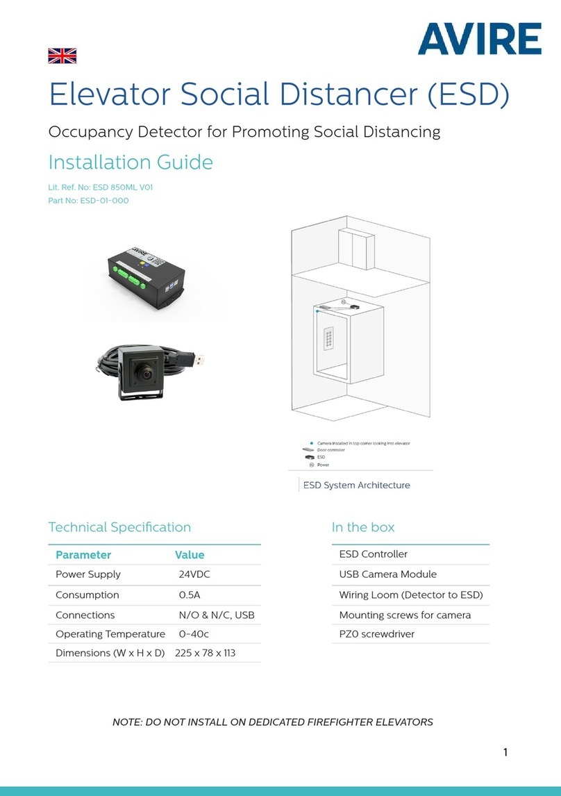
AVIRE ESD User manual

AVIRE

AVIRE ESD User manual

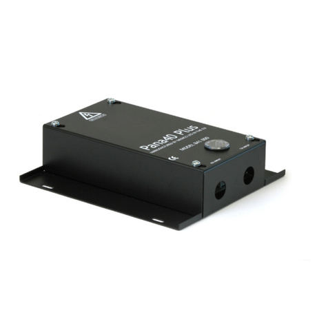
AVIRE MEMCO Pana40 Plus User manual

AVIRE

AVIRE MEMCO Pana40 Plus User manual

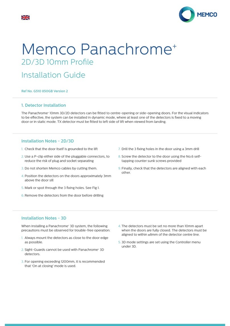
AVIRE Memco Panachrome+ User manual

AVIRE

AVIRE Memco Panachrome+ User manual

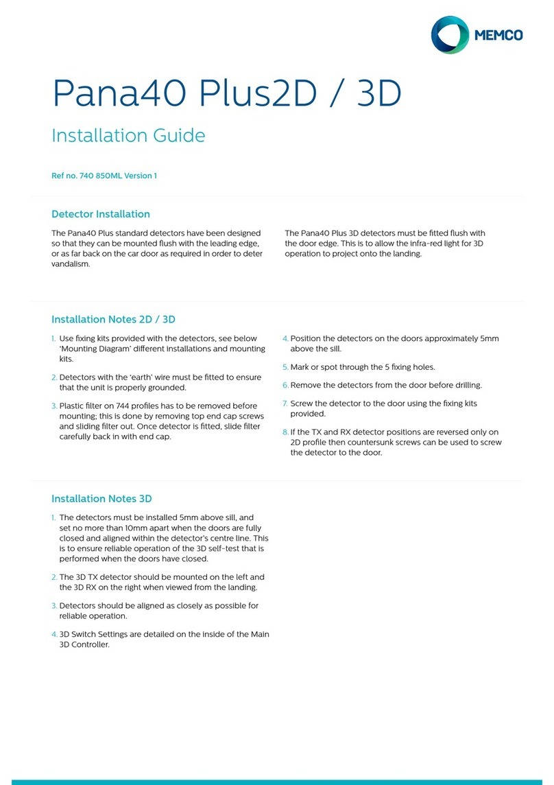
AVIRE MEMCO Pana40 Plus2D User manual

AVIRE

AVIRE MEMCO Pana40 Plus2D User manual

Popular Security Sensor manuals by other brands

Paradox NV37MX installation manual

Paradox

Paradox NV37MX installation manual

InnoLux Yushan Series Operation manual

InnoLux

InnoLux Yushan Series Operation manual

Datalogic SG2 BASE Series Original instructions

Datalogic

Datalogic SG2 BASE Series Original instructions

T&D Martindale Electric TEK500 instructions

T&D

T&D Martindale Electric TEK500 instructions

Andersen Verilock 0106512 user guide

Andersen

Andersen Verilock 0106512 user guide

PPA SENSOR SMART SLIM PET user manual

PPA

PPA SENSOR SMART SLIM PET user manual

Powerfix Profi 40111 Operation and safety notes

Powerfix Profi

Powerfix Profi 40111 Operation and safety notes

Honeywell NFPA 1951 User's information guide

Honeywell

Honeywell NFPA 1951 User's information guide

Durite 0-870-58 Product installation manual

Durite

Durite 0-870-58 Product installation manual

Visonic TOWER-20AM PG2 Specifications

Visonic

Visonic TOWER-20AM PG2 Specifications

Nice HSDIM11 installation instructions

Nice

Nice HSDIM11 installation instructions

Essence Smartcare Care@Home MDsense Getting started

Essence Smartcare

Essence Smartcare Care@Home MDsense Getting started

DINUY DM K5X 001 manual

DINUY

DINUY DM K5X 001 manual

smartmicro UMRR-11 45 user manual

smartmicro

smartmicro UMRR-11 45 user manual

Ateis VELOX LV350 quick start guide

Ateis

Ateis VELOX LV350 quick start guide

RKI Instruments 65-2423RK-05 Operator's manual

RKI Instruments

RKI Instruments 65-2423RK-05 Operator's manual

Crowcon Cardinal M07231 instruction manual

Crowcon

Crowcon Cardinal M07231 instruction manual

WCP Leak Controller LCS25 Installation and operation guide

WCP

WCP Leak Controller LCS25 Installation and operation guide

manuals.online logo
manuals.online logoBrands
  • About & Mission
  • Contact us
  • Privacy Policy
  • Terms and Conditions

Copyright 2025 Manuals.Online. All Rights Reserved.