Installation
Before the installation, making sure the selector an
monitor (projector) are turning off.
1. Making sure all equipments are turne off.
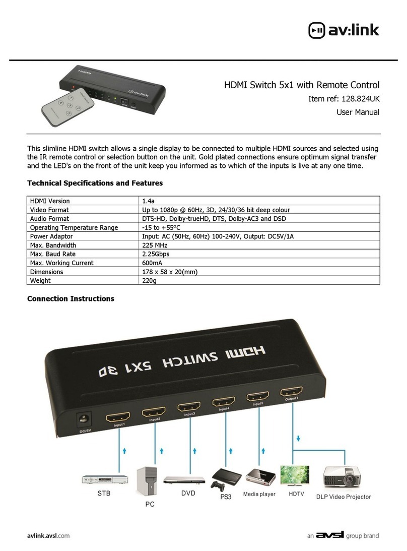
2. Plug the monitor cable into the HDMI OUT port
connector.
3. Plug the extension cables from HDMI port of DVD
player/TV receiver into the HDMI IN port connectors.
4. Plug the power a apter into the wall socket.
5. Connect the power a apter with the HDMI selector.
6. Turn on the monitor first.
7. All re LEDs will flash back an forth, otherwise, go
back to check the step 4 an 5.
8. Turn on the DVD player/TV receiver.
9. The LEDs green light turn on while the DVD player/TV
receiver have well been connecte an maintaining
the activation.
Operation
1. Port selection
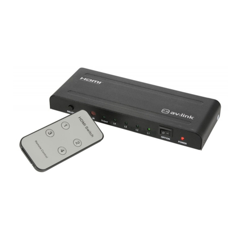
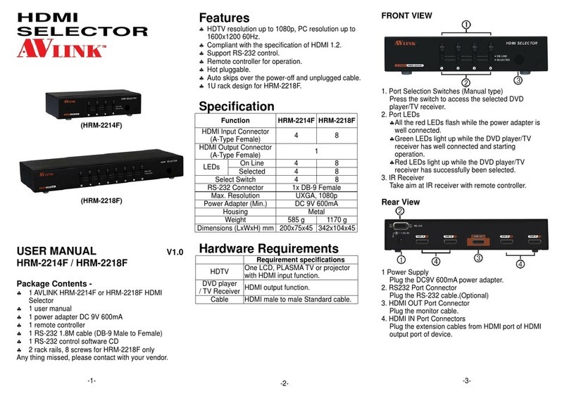
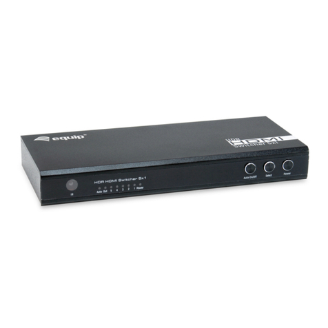
Press the button of “port selection switch” for
accessing the wante DVD player/TV receiver.
The selecte correspon ing port will light on for the
re LEDs which in icating the port is active .
2. IR remote control
Use “1”, ”2” key to select DVD player/TV receiver
that wante DVD player/TV receiver.
Use “
▲
”, “
▼
” key to select another DVD
player/TV receiver.
3. RS-232 control
You can operate an configure the Switcher via a remote
terminal session using RS-232. Follow the steps as
below to log into the Switcher by means of a RS-232
session (the example as below is for Hyper Terminal):
1. Connect the Switcher to your control PC with RS-232
cable.
2. Power on both Switcher an control PC.
3. Open the Hyper Terminal by clicking
Start│Programs│Accessories
Communications│Hyper Terminal on your control PC.
4. The New Connection – Hyper Terminal screen will
appear. Input the connection name an select a
representative icon. Then click OK.
5. Select the connecting port that you want to use, click
OK. Default port is COM1.
-4-
6. Set the Bits per secon to 9600, Data Bits to 8
(Default), Parity to None (Default), Stop bits to 1
(Default) an flow control to None from the rop- own
list, click OK.
Technical Specifications
HDMI Input/Output Si nal
1 TMDS Data 2+ 11 TMDS Clock Shiel
2 TMDS Data 2 Shiel 12 TMDS Clock -
3 TMDS Data 2- 13 CEC
4 TMDS Data 1+ 14 Reserve
(N.C. on evice)
5 TMDS Data 1 Shiel 15 SCL
6 TMDS Data 1- 16 SDA
7 TMDS Data 0+ 17 DDC/CEC Groun
8 TMDS Data 0 Shiel 18 +5 Power
9 TMDS Data 0- 19 Hot Plug Detect
10 TMDS Clock+
Supported RS232 DCE Si nal
