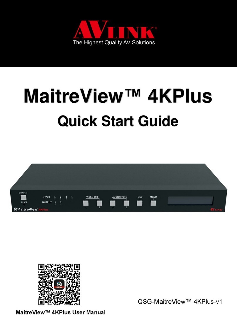
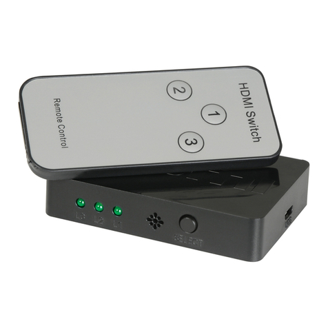
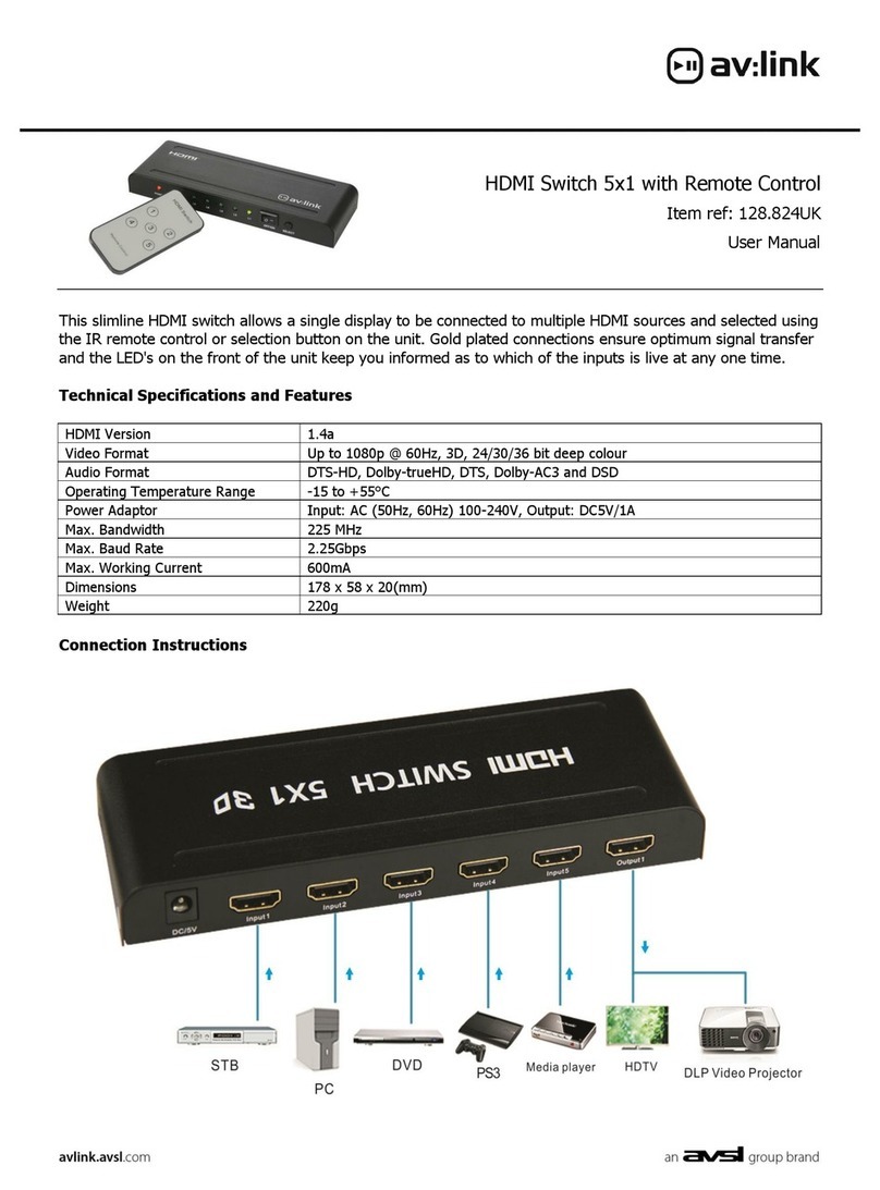
AVLink VAX-2044 User manual

User Manual
VAX-2044 VAX-2084
VAX-2088
VAX Series Matrix Switching Systems

VAX Matrix Switching System—User Manual
1
Before You Use the System
1、Read manual——Carefully read the manual before you use the system.
2、Installation environment——The system should be installed indoor only. Install either on a
sturdy rack or desk in a well-ventilated place.
3、Lightning——Unplug the power cord during lightning or after a prolonged period of non-use
to avoid damage to the equipment.
4、Maintenance——Only qualified technical engineers or specified distributors are permitted to
repair or replace components and parts of the equipment upon failure.

VAX Matrix Switching System—User Manual
2
Table of Contents
1.0 Matrix System Overview ..........................................................................................................4
1.0.1 VAX Matrix System.......................................................................................................4
1.0.2 VAX Matrix System Packing.........................................................................................4
2.0 VAX Matrix Host Installation ...................................................................................................5
3.0 VAX Matrix System Models.....................................................................................................6
4.0 Matrix System Front/Rear Panels .............................................................................................6
4.0.1 VAX-2044 Front/Rear Panels.........................................................................................6
4.0.2 VAX-2084 Front/Rear Panels.........................................................................................7
4.0.3 VAX-2088 Front/Rear Panels.........................................................................................7
5.0 VAX Matrix and Peripherals Connection..................................................................................8
5.0.1 Input/Output Jacks..........................................................................................................8
5.0.1.1 Video Connecting Cable......................................................................................8
5.0.1.2 Audio Connecting Cable ...................................................................................10
5.0.2 VAX Matrix and Control Computer Connection .........................................................11
5.0.3 Remote Control Methods and Settings.........................................................................11
5.0.3.1 RS-232 Communication Port, Connection Methods.........................................11
5.0.3.2 RS-485 Communication Port............................................................................14
5.0.3.3 On/Off Switch Settings .....................................................................................14
5.0.3.4 VAX Matrix System and Control System Connection......................................16
6.0 Matrix Control Panel Operation..............................................................................................18
6.0.1 Input/Output Switching Key Operation Mode.............................................................18
6.0.2 Front Panel Key Functions...........................................................................................18
6.0.3 Operation Examples.....................................................................................................19
7.0 Matrix Application Software...................................................................................................22
7.0.1 Software Introduction...................................................................................................22
7.0.1.1 Software Description.........................................................................................22
7.0.1.2 Software Activation...........................................................................................22
7.0.2 Software Features.........................................................................................................22
7.0.2.1 Main Operation Interface Functions .................................................................23
7.0.2.2 Disconnect Function Keys ................................................................................25
7.0.2.3 Select all output, DeSelect all output Switching Functions..............................26
7.0.2.4 Disconnect all Command..................................................................................26
7.0.2.5 Memory Function Usage...................................................................................26
7.0.2.6 Scan Function Usage.........................................................................................27
7.0.2.7 Options Function Usage....................................................................................27
7.0.2.8 Exit Function Usage..........................................................................................28
7.0.2.9 Other Usages.....................................................................................................28

VAX Matrix Switching System—User Manual
3
8.0 Communication Protocol and Control Command Code .........................................................28
9.0 VAX Matrix System Technical Parameters.............................................................................29
10.0 Common Problems and Solutions.........................................................................................30

VAX Matrix Switching System—User Manual
4
1.0 Matrix System Overview
1.0.1 VAX Matrix System
The VAX Matrix switcher is a high performance switching equipment for video and audio
frequency. It is used for input/output cross switching of multi-video and audio frequency signals.
It provides separate video and audio jacks for separate transmission of each video frequency
component signal and audio frequency signal, thereby minimizing signal attenuation and
ensuring high definition and high fidelity graphics and audio signal output.
The VAX Matrix is used mainly in TV broadcasting projects, multi-media conference halls,
large display projects, TV teaching and command control centers. It boasts features of power
interruption protection during power surge, LCD display and synchronous and separate
audio/visual switching functions. Its RS-232 communication port enables convenient
communication with remote control equipment. This manual describes using of the VAX-2088
model. Refer to VAX-2088 User Manual for using of other models of matrix systems.
Figure 1-1 VAX 2088 Matrix
1.0.2 VAX Matrix System Packing
VAXMatrixHost
RS-232 Communication Connecting Cable

VAX Matrix Switching System—User Manual
5
PowerCord
VAXMatrixTestandApplicationSoftwareCD
UserManual
2.0 VAX Matrix Host Installation
The VAX Series Matrix Host has a black metallic housing. It can be placed on a sturdy desk or
installed on a 19-in rack. See Figure 2-1 below:
Figure 2-1 Installing the VAX Matrix Host on a Standard Rack
Green Terminal(M)Quantity
VAX-2044 10 Pcs
VAX-2084 14 Pcs
VAX-2088 18 Pcs

VAX Matrix Switching System—User Manual
6
3.0 VAX Matrix System Models
The VAX Series Matrix has following models to meet different requirements of different
users:
Technical
Parameters
Model
Video
Input Jack
Video
Output
Jack
Audio
Input Jack
Audio
Output
Jack
RS-485
Port
RS-232
Port
VAX-2044 4 4 4 4 √√
VAX-2084 8 4 8 4 √√
VAX-2088 8 8 8 8 √√
4.0 Matrix System Front/Rear Panels
4.0.1 VAX-2044 Front/Rear Panels
Figure 4-1 VAX-2044 Front Panel
Figure 4-2 VAX-2044 Rear Panel

VAX Matrix Switching System—User Manual
7
4.0.2 VAX-2084 Front/Rear Panels
Figure 4-3 VAX-2084 Front Panel
Figure 4-4 VAX-2084 Rear Panel
4.0.3 VAX-2088 Front/Rear Panels
Figure 4-5 VAX-2088 Front Panel
Figure 4-6 VAX-2088 Rear Panel

VAX Matrix Switching System—User Manual
8
5.0 VAX Matrix and Peripherals Connection
Figure 5-1 VAX Matrix System Connection
5.0.1 Input/Output Jacks
Referring to the different models, the video signal input/output jacks are formed by the 4th
row and 8th row VGAfemale terminals. The audio input/output jacks are formed by the 4th and
8th row 5-phase 3.8mm connection terminals. The VAX-2088 video signal input/output terminal
channels are numbered from lower to upper and from left to right as NO.1 to NO.8 channels (in
two rows). The video port is the video signal terminal. The audo signal input/output terminal
channels are numbered from left to right as NO.1 to NO.8. Refer to the drawing on the housing
for port terminals of different models.
Different models of the VAX matrix system provides a different number of input/output
jacks for users to connect to different audio/visual equipment including CD/DVD players,
graphics workstations, and number displays. The output terminals can be connected to projectors,
video recorders, displays and multiplexers and so on.
5.0.1.1 Video Connecting Cable
Data processed by the display card will ultimately be output to the display, and the display
output connector bridges together the computer and the display. It is responsible to output
corresponding graphics signals to the display. Due to design and manufacturing, the CRT
monitor can only receive analog signals, thereby the display card must also be able to input
analog signals. The VGA (Video Graphics Array) connector, also called D-Sub conector, is the
connector of graphics card for output of analog signals. Although the LCD display can directly
receive digital signals, many low-end products still use VGA connectors for connection to the

VAX Matrix Switching System—User Manual
9
VGA card. The VGA connector is a D-sub connector with 15 pins in 3 rows (each row has 5
pins).
Presently, most computers connect with external displays via analog VGA connectors. The
computer internally generates digital graphics data to be converted by the graphics card
digital/analog converter into the R, G, and B process color signals, and coutour and gamut
synchronous signals which are transmitted to the display via the cable. Regarding analog display
equipment such as the analog CRT display, the signals are being sent directly to the
corresponding processor circuit and drive the controlling Cathode Ray Tube into graphics display.
Digital displays such as LCD and DLP are usually equipped with A/D (Analog/Digital)
converters to convert analog signals into digital signals. Unavoidably, some losses to graphics
happen after two times of conversion from analog to digital and vice versa. It’s understandable to
use VGAconnectors in CRT monitors, but to use it in LCD displays the quality of graphics
display is likely to degrade in the process of conversion.
Different models of the VAX matrix system provides a different number of input/output
jacks for users to connect to different audio/visual equipment including CD/DVD players,
graphics workstations, and number displays. The output terminals can be connected to projectors,
video recorders, displays and multiplexers and so on.
The RCA connecting terminal----audio/video port: The 4-hole RCA Jack is a conventional
audio connector. Its installation hole measures 14x18mm.
The VAX Matrix supports various AV signal sources.
AV Connector—standard AV Input RCA)Connector:
Type:Audio connectors are in pairs (left/right channels) (white/red) and video connector
(yellow)
VAX matrix RCA jack connection, see Figure 5-2 below:

VAX Matrix Switching System—User Manual
10
Pin No. Name Description
1 RED Red video signal
2 GREEN Green video signal
3 BLUE Blue video signal
4 n.c. No connect
5 GND Ground
6 RED_RTN Red video signal return
7 GREEN_RTN Green video signal return
8 BLUE_RTN Blue video signal return
9 n.c. No connect
10 GND Ground
11 n.c. No connect
12 SDA I2C data
13 HSYNC Horizontal synchronization
signal
14 VSYNC Vertical synchronization signal
15 SCL I2C clock
Figure 5-2 VGA Connecting Cable
5.0.1.2 Audio Connecting Cable
Compared to the video connecting cable, the audio connecting cable has two different ways
of connection: the balanced and the unbalanced connection.
The “Audio Inputs” and “Audio Outputs” connectors of the VAX matrix are for connection
to the video players audio signal and multiplexers.
Balanced connection is a connection method of using two signal wires to transmit a pair of
balanced signals. Since interference to two signal wires are similar and out of phase the
interfering signals are cancelled out.The lower audio frequencies are susceptible to interference
in long distrance transmission. Therefore, balanced connection is a way to counter interference
commonly used in professional audio equipment. In household appliances, two-wire cable with
sleeve is sometimes used. However, they are used for the left and right audio signal channels and
do not belong to balanced connection.
Unbalanced connection uses only one signal cable for connection and is susceptible to
interference. Most household appliances and not-so-demanding audio equipment uses
unbalanced connection.
A specific connection of the audio signal cable is given below:
1. Unbalanced connection: The “G” leg connects to the Sleeve, and the “+” leg
connects to the red wire (TIP) while the “-“ leg connects to the “G” leg.

VAX Matrix Switching System—User Manual
11
2. Balanced connection: The “G” leg connects to the Sleeve, and the “-“ leg connects
to the black wire (RING) while the “+” leg connects to the red wire (TIP). Refer to
Figure 5-3 below:
Figure 5-3 5-Phase 3.8mm Audio Connecting Socket Cable(Balanced/Unbalanced
Connection)
To select balanced or unbablanced connection is often depended on the connectors of the
equipment. Use balanced connection as far as possible. Refer to the User Manual prior to
connection. Occasionally, you will have to connect balanced connectors of one piece of
equipment to unbalanced connectors of another equipment. In most cases, you can use
unbalanced connection at the balanced end if quality is not so demanding. If you are demanding
for audio quality, you must use a balun to convert a signal from balanced to unbalanced, or vice
versa.
5.0.2 VAX Matrix and Control Computer Connection
Use the RS-232 connecting cable to connect the computer serial port (COM1 or COM2) to
the RS-232 communication port of the VAX matrix host. The computer can then be used to
control the VAX matrix after installation of application software.
Figure 5-4 VAX Matrix and Computer Connection
5.0.3 Remote Control Methods and Settings
The VAX matrix provides standard RS-232 and RS-485 serial communication ports. Aside
from using the front panel keys for switching operation, you are also permitted to use the RS-232
and RS-485 serial communication ports for remote operation. It also supports RS-485 serial
control.
5.0.3.1 RS-232 Communication Port, Connection Methods
The RS-232 port is a 9-pin female connector. The Leg functions are shown in the table
below:

VAX Matrix Switching System—User Manual
12
Pin No. Leg Description
1 N/u Null
2 Tx Send
3 Rx Receive
4 N/u Null
5 Gnd Ground
6 N/u Null
7 N/u Null
8 N/u Null
9 N/u Null
Figure 5-5

VAX Matrix Switching System—User Manual
13
Figure 5-5(a)
Figure 5-6
Note: The Matrix RS-232 port is defined as DCE.

VAX Matrix Switching System—User Manual
14
5.0.3.2 RS-485 Communication Port
You can use the RS-485 port to control more than one VAX product.
The RS-485 Port as shown in Figure 5-7 below:
Figure 5-7
5.0.3.3 On/Off Switch Settings
Figure 5-8
A. DIP SW-8:RS-232/RS-485 switches ON/OFF
ON:RS-232 Enables Single System or RS-485 Serial Master
OFF:RS-485 Enables RS-485 Serial Slave
B. DIP sw-6/7:RS-485 Terminator ON/OFF
ON:TerminatorON
OFF:TerminatorOFF
C. DIP sw 1 to 5 Setting(address setting)
The ID address determines the position of a VAX Matrix system. When multiple VAX
products are connected to one PC or when the Matrix products are serially connected, the ID
address decides which VAX product is to be controlled. Use the on/off switches 1, 2, 3, 4, 5 on
the rear panel to set the ID address as shown in Table 5-2 below:

VAX Matrix Switching System—User Manual
15
ON/OFF Switch SettingsID Address
(Decimal)
Software ID
Address
(Hexadecimal)
ON/OFF
(Binary)SW1 SW2 SW3 SW4 SW5
0 00 00000 OFF OFF OFF OFF OFF
1 01 00001 OFF OFF OFF OFF ON
2 02 00010 OFF OFF OFF ON OFF
3 03 00011 OFF OFF OFF ON ON
4 04 00100 OFF OFF ON OFF OFF
5 05 00101 OFF OFF ON OFF ON
6 06 00110 OFF OFF ON ON OFF
7 07 00111 OFF OFF ON ON ON
8 08 01000 OFF ON OFF OFF OFF
9 09 01001 OFF ON OFF OFF ON
10 0A 01010 OFF ON OFF ON OFF
11 0B 01011 OFF ON OFF ON ON
12 0C 01100 OFF ON ON OFF OFF
13 0D 01101 OFF ON ON OFF ON
14 0E 01110 OFF ON ON ON OFF
15 0F 01111 OFF ON ON ON ON
16 10 10000 ON OFF OFF OFF OFF
17 11 10001 ON OFF OFF OFF ON
18 12 10010 ON OFF OFF ON OFF
19 13 10011 ON OFF OFF ON ON
20 14 10100 ON OFF ON OFF OFF
21 15 10101 ON OFF ON OFF ON
22 16 10110 ON OFF ON ON OFF
23 17 10111 ON OFF ON ON ON
24 18 11000 ON ON OFF OFF OFF
25 19 11001 ON ON OFF OFF ON
26 1A 11010 ON ON OFF ON OFF
27 1B 11011 ON ON OFF ON ON
28 1C 11100 ON ON ON OFF OFF
29 1D 11101 ON ON ON OFF ON
30 1E 11110 ON ON ON ON OFF
31 1F 11111 ON ON ON ON ON
Table 5-2 IDAddress Settings

VAX Matrix Switching System—User Manual
16
5.0.3.4 VAX Matrix System and Control System Connection
A. If PC provides RS-232,connection is as in Figure 5-9 below:
Figure 5-9
NOTE: 1. For RS-232 connection refer to previous Figure for operation;
2. RS-232 and RS-485 baud rates: 9600bps, no odd or even calibration address, 8bit data
transmission address, 1bit stop address(96,N,8,1);
3. Serial connection between Matrix RS-485 as follows:
TX(+)TX(+)
TX(-)TX(-)
RX(+)RX(+)
RX(-)RX(-)
4. Each DIP sw1-5 address must not set to same ID address.

VAX Matrix Switching System—User Manual
17
B. If PC provides RS-485, connection is as in Figure 5-10 below:
Figure 5-10
NOTE: 1. RS-485 baud rate: 9600bps, no odd or even calibration address,8bit data transmission
address,1bit stop address(96,N,8,1);
2. Connect your PC RS-485 port to the Matrix RS-485 port as follows:
TX(+)TX(+)
TX(-)TX(-)
RX(+)RX(+)
RX(-)RX(-)
3. Serial connection between Matrix RS-485 ports as shown below:
TX(+)TX(+)
TX(-)TX(-)
RX(+)RX(+)
RX(-)RX(-)
4. Each DIP sw1-5 address must not set to same ID number.

VAX Matrix Switching System—User Manual
18
6.0 Matrix Control Panel Operation
6.0.1 Input/Output Switching Key Operation Mode
You can use the front panel keys of the VAX Matrix system for fast audio/video switching.
(For details in key pressing, refer to the “Front Panel Key Pressing Instructions”.)
Operation methods as follows:
“Switching Methods” + “Output Channel"+“Input Channel"
Description: ‘
“Switching Methods”
Synchronous audio/video switching or separate switching: Using the “Audio” and “Video” keys
on the front panel, you can select “Synchronous Audio/Video Switching,” “Audio Switching
Only” or “Video Switching Only.”
“Output Channel"
The “OUT Row 1-8” keys on the front panel represent output channels 1 to 8 for connection to
peripheral display.
“Input Channel"
The “IN Row 1-8” keys on the front panel represent input channels 1 to 8 for connection to the
currently connected channels of the signal source to be switched.
6.0.2 Front Panel Key Functions
Part Function Key Function
1
LCD display shows current VAX matrix status and
operation hints.
2 Output channel selection keys used for setting
audio/video output channels or for selection of Status
Retrieve or Stored Number.
3 Input channel selection keys used for setting audio/video
input channels or for selection of Status Retrieve or
Stored Number.
4
ALL
Implement all output selection keys via certain input
route.
---Example: First press the “ALL” key, then select the
input channel to output to all output channels; first press
the “ALL”key, then press the “OFF” key to close all the
presently displayed swtitching status.

VAX Matrix Switching System—User Manual
19
Part Function Key Function
5
OFF
Close output channel key.
---First press to close the output channels, then press the
“OFF” key to close the specified output channel.
6
STO
The “Store Key” saves all current input/output
corresponding relations.
---Example: Press the “STO”key, then press the output
channel key which you want to save all currently
displayed input/output corresponding relations.
7
RCL
The “Retrieve Key” retrieves the saved input/output
corresponding relations.
---Example: First press the “RCL” key, then press the
previously saved output channel key to retrieve the saved
input/output status and implement this status switching.
8
AUDIO
The audio switching selection key switches to another
output channel from the same channel.
Example: Press the Audio key to open or close the Audio
switching function. When the LED indicator next to the
Audio key lights shows switching function is open and
when the light goes off shows you have selected to close
the audio switching function.
9
VIDEO
The video switching selection key switches to another
output channel from the same channel.
Example 1: Press the Video key to open or close the
video switching function. When the LED indicator next
to the Video key shows video switching function is open
and when the light goes off shows the switching function
is close.
6.0.3 Operation Examples
Examle 1: Synchronously switch the NO. 1 audio/video signals to the NO. 3 and 4 output
channels.
This manual suits for next models
2
Table of contents
Other AVLink Switch manuals
AVLink
AVLink HRM-602P User manual
AVLink
AVLink HX-1542W User manual

AVLink
AVLink IC-714AUHR User manual
AVLink
AVLink HRM-2214F User manual

AVLink
AVLink HRM-2514 User manual
AVLink
AVLink 128.822UK User manual

AVLink
AVLink MaitreView 4KLite User manual

AVLink
AVLink 128.822UK User manual
AVLink
AVLink 128.823UK User manual
AVLink
AVLink 128.841UK User manual
Popular Switch manuals by other brands
LEGRAND
LEGRAND Wattstopper InteliSwitch AS-100 quick start guide
3Com
3Com AS Series ASM200 supplementary guide

HPE
HPE FlexNetwork 10500 SERIES Security command reference
D-Link
D-Link DWS-3227P - xStack Switch - Stackable datasheet

Tormach
Tormach PCNC 440 owner's guide
Raritan
Raritan SwitchMan USB-Combo SW2 user manual
