Latest products and information available at www.avlite.com
3
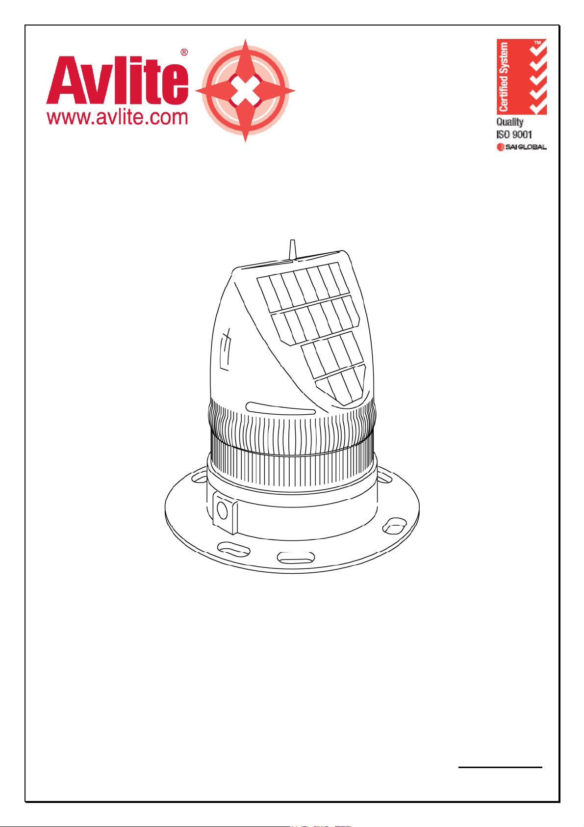
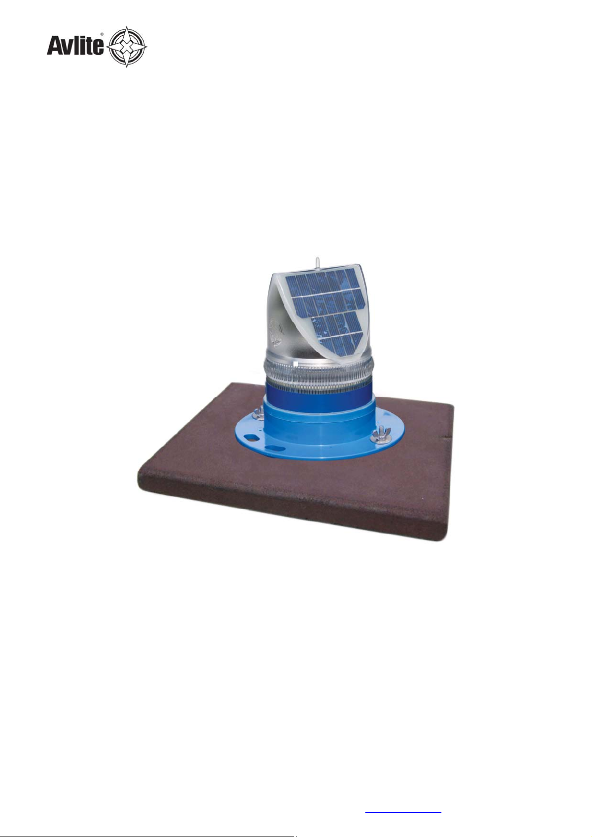
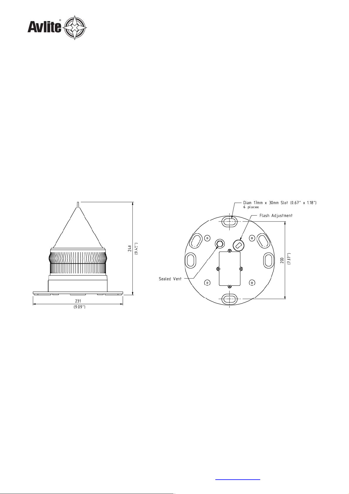
AV70 Solar Airfield Light
Table of Contents
1General...................................................................................................................4
1.1 Introduction ............................................................................................................4
1.2 Features..................................................................................................................4
1.3 Specifications ..........................................................................................................6
2Technical Description.............................................................................................7
3Assembly & Installation.........................................................................................8
3.1 Assembly & installation of the AV70 with rubber tile ...................................................8
3.1.1 Unpacking instructions........................................................................................8
3.1.2 Initial inspection.................................................................................................8
3.1.3 Assembly...........................................................................................................8
3.1.3.1 Assembling the light.....................................................................................8
3.1.3.2 Installing the light assembly .......................................................................10
3.2 Assembly & installation of the AV70 with Frangible Stake Mount................................11
3.2.1 Unpacking instructions......................................................................................11
3.2.2 Initial inspection...............................................................................................11
3.2.3 Assembly.........................................................................................................11
3.2.3.1 Assembling the light...................................................................................11
3.2.3.2 Installing the light assembly .......................................................................13
4Maintenance and Servicing..................................................................................14
4.1 General Maintenance..............................................................................................14
4.2 Replacing the Battery.............................................................................................14
4.3 Charging the Battery..............................................................................................14
5Trouble Shooting..................................................................................................15
Introduction
Congratulations! By choosing to purchase an Avlite lantern you have become the owner of one of the most
advanced solar LED airfield lights in the world.
Avlite Systems draws on more than 20 years experience in the design and manufacture of navigation aids, and
particular care has been taken to ensure your light gives years of trouble free service.
As a commitment to producing the highest quality products for our customers, Avlite has been independently
certified as complying with the requirements of ISO 9001:2000 quality management system.
By taking a few moments to browse through this booklet, you will become familiar with the versatility of your light,
and be able to maximise its operating function.
Please remember to complete the Avlite warranty registration card accompanying your lantern.