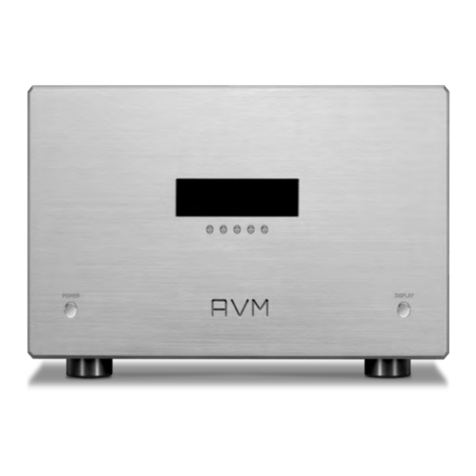
AVM INSPIRATION SD 2.2 User manual

1
Operating instructions
INSPIRATION SD 2.2

2

3
Declaration of conformity (for EC only)
We herewith confirm, that the unit to which this manual belongs fulfills the EC rules necessary
to obtain the sign
the necessary measurements were taken with positive results.
AVM Audio Video Manufaktur GmbH
Daimlerstraße 8
D-76316 Malsch
Germany
www.avm.audio
info@avm.audio

4
Dear customer
Thank you for purchasing this AVM product. You now own a versatile, excellent sounding hifi
component. Before enjoying music, please read this manual carefully. After that you will know
how to use your new SD 2.2 in the optimal way.
Please note that the range of functions of your AVM hifi component can be easily expanded by
means of a software update at any time. Hence, the present operating instructions will require
continued updates going forward. You you can always download the most current version from
our website at www.avm.audio.
Sincerely yours,
The AVM Team

5
Table of contents
1!Getting started...................................................................................................................... 6!
1.1!What’s in the box? .......................................................................................................... 6!
1.2!Control and operating elements...................................................................................... 6!
1.3!Installation and cooling ................................................................................................... 7!
1.4!Connection to mains ....................................................................................................... 7!
1.5!Connecting digital sources.............................................................................................. 7!
1.6!Connecting analogue signal sources .............................................................................. 8!
1.7!Connecting a recorder .................................................................................................... 8!
1.8!RC 9 remote control........................................................................................................ 8!
1.9!RC S App for iOS and Android........................................................................................ 8!
1.10!Network installation (LAN, WiFi) .................................................................................... 8!
1.11!Software updates ........................................................................................................ 12!
2!Basic operation .................................................................................................................. 13!
2.1!First operation / self test ............................................................................................... 13!
2.2!Switching on / stand by................................................................................................. 13!
2.3!Selecting a signal source .............................................................................................. 13!
2.4!Volume setting............................................................................................................... 13!
2.5!Setting of input sensitivity ............................................................................................. 14!
2.6!Samplerate and filter settings ....................................................................................... 14!
3!Advanced Settings ............................................................................................................. 15!
3.1!Global settings .............................................................................................................. 15!
3.2!Personal Setup.............................................................................................................. 16!
3.3!Reset (factory default settings)...................................................................................... 17!
4!RC 9 Fernbedienung (optionally available) ...................................................................... 18!
4.1!Overview........................................................................................................................ 18!
4.2!Activation and stand by mode ...................................................................................... 19!
4.3!Battery charge............................................................................................................... 19!
4.4!Colour display ............................................................................................................... 19!
4.5!Entry of letters, numbers, and characters..................................................................... 20!
4.6!Hotkeys ......................................................................................................................... 20!
4.7!System settings............................................................................................................. 20!
4.8!Source Menu ................................................................................................................. 23!
4.9!Receiver Settings .......................................................................................................... 26!
5!Appendix ............................................................................................................................. 27!
5.1!Cleaning ........................................................................................................................ 27!
5.2!Troubleshooting ............................................................................................................ 27!
5.3!Conditions of warranty (EC only)................................................................................... 28!
6!Technical Data.................................................................................................................... 28!

6
1Getting started
1.1 What’s in the box?
•INSPIRATION SD 2.2
•WLAN antenna
•Power cable
•Optional accessory: RC 9 remote control with docking station, power supply unit,
USB charging cable
CAUTION: After unpacking, please check the scope of delivery to ensure that all parts have
been supplied and are undamaged. In case the original packing has already been opened,
please contact your local dealer. Often, your dealer prepares your new device prior to delivery
to adapt and change the configuration to your personal needs.
1.2 Control and operating elements
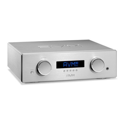
The numbers in the drawings below mark the control elements. They refer to the numbers in
the text, where the operation of the unit is described.
1Power button (on / off)
2Control LED
3Display
4Multifunctional button a
5Multifunctional button b
6Multifunctional button c
7Multifunctional button d
8Multifunctional button e
9Source Selector
10 Source Selector
11 Mute button
12 Headphone output
13 Volume knob

7
14 Digital output (Optical)
15 Digital output (Coaxial)
16 Analogue output right (XLR)
17 USB B input
18 Analogue outputs (Cinch)
19 Digital inputs (Optical)
20 Analogue output left (XLR)
21 Digital inputs (Coaxial)
22 Line inputs (Cinch)
23 Configuration port (Firmware)
24 Trigger outputs
25 Network port (LAN)
26 USB input
27 WiFi antenna socket
28 Status LED
29 Update button
30 Reset button
31 Mains connector
32 Mains switch
1.3 Installation and cooling
The unit can become hot depending on demanded output power or environmental
temperature. Therefore it is important, that the cooling air can flow unhindered into the air
inlet in the bottom and flow out through the holes in the rear panel. Direct exposure to
sunlight is not recommended because this will heat up the unit.
1.4 Connection to mains
Connect the unit to the mains outlet (31) by using the power cord which is (in some countries)
delivered together with the unit. Make sure that mains voltage is according to the value
printed on the rear panel of the amp (near mains connector).
CAUTION: Keep the unit switched off until all audio connections are made.
1.5 Connecting digital sources
Connect the outputs of your digital sources to the corresponding digital inputs of the SD 2.2
(17, 19, 21). You con choose two optical inputs (19), two coaxial inputs (21), or the USB B
digital input (17).

8
1.6 Connecting analogue signal sources
Connect the outputs of your signal sources to the analogue inputs (22). The upper row is for
the left channel, the lower row is for the right channel.
1.7 Connecting a recorder
The input of a digital recorder must be connected to the digital outputs (14, 15). The signal on
the digital outputs depends on the selected source such as DIG COAX, DIG OPT.
1.8 RC 9 remote control
The optionally available RC 9 remote control allows for easy and comprehensive control of
the SD 2.2. Before you can use the RC 9 together with your SD 2.2, both components need
to be connected. This process is also referred to as Pairing. In order to start the pairing
process, please follow the instructions as described in section 4.7.5. For a detailed
description of functions and features of the optionally available RC 9 remote control, please
refer to chapter 4.
1.9 RC S App for iOS and Android
The RC S App for iOS and Android will turn your smartphone or tablet into an easy-to-use
remote control and provides a variety of intuitive features to get the most out of your network-
enabled AVM device. The RC S App is available free of charge and can be downloaded from
the Apple App Store and the Google Play Store. For detailed instructions on how to set-up
your AVM device with the RC S App, please refer to the RC S User Guide which can be
downloaded from our website at www.avm.audio.
1.10 Network installation (LAN, WiFi)
In order to use the integrated streaming functions (e.g. TIDAL, Airable, Webradio, Musik-
Server etc.) your SD 2.2 needs to be connected to the internet via a router in your home
network. You can choose from a wired ethernet connection (LAN) (25) or a wireless WiFi
connection (27). In order to use the WiFi connection of the SD 2.2, the included WiFi antenna
needs to be installed. Please follow the instructions below to connect your SD 2.2 to your
local home network.
1.10.1 Network installation: Wired ethernet connection (LAN)
üPlease switch off the SD 2.2 on the rear side of the unit (32).
üPlug an ethernet cable from your local router into the network port of the SD 2.2 (25).

9
üSwitch on the SD 2.2 on the rear side of the unit (32). Wait until the device has started and
went into stand by mode. Now, switch it on with the power button on the front side (1).
üAfter a brief starting process your SD 2.2 automatically connects to your local home
network and is ready to be operated via RC S App for iOS and Android.
1.10.2 Network installation: Wireless connection (WiFi)
In order to set up the SD 2.2 with a wireless connection, you need to download and install the
free RC S App for iOS and Android or the optionally available RC 9 remote control.
CAUTION: Before using the wireless functionality of the SD 2.2 an initial set-up of a wired
ethernet connection (LAN) according to the steps described in section 1.10.1 is required.
üPlease switch off the SD 2.2 on the rear side of the unit (32).
üPlug an ethernet cable from your local router into the network port of the SD 2.2 (25).
üSwitch on the SD 2.2 on the rear side of the unit (32). Wait until the device has started and
went into stand by mode. Now, switch it on with the power button on the front side (1).
üAfter a brief starting process your SD 2.2 automatically connects to your local home
network and is ready to be operated via the RC S App for iOS and Android.
üLaunch the RC S App on your smartphone or tablet. The RC S App will now automatically
search and list all available AVM devices in your local network with their respective device
name and IP adress (e.g. "192.168.xxx.x" or "10.0.1.4").
üChoose one of the availbale devices and wait until a connection is established between
your RC S App and the SD 2.2 .

10
üNavigate to the Settings tab on the RC S App and choose Device Settings / Network /
Configure WiFi.
üAfter you have selected the SSID menu option, you will be provided with a list of all
available WiFi networks. Choose a WiFi network and select a respective Security and
Cipher setting.

11
üChoose the menu option Password and enter your WiFi password. Confirm with Done at
the upper right-hand corner. Now, confirm your WiFi settings with Apply at the upper
right-hand corner.
üUnder DHCP, you will be asked if your SD 2.2 should obtain an IP adress automatically (if
yes, please make sure the DHCP option is activated). Now, confirm your choice with
Apply at the upper right-hand corner.
CAUTION: Unless your local home network has been configured with static IP
addresses, we highly recommend to activate the DHCP option, which is the most
common use case.
üNow, choose Restart at the upper right-hand corner in order to restart the integrated SD
2.2 streaming module. Please make sure to not switch off the device while the device is
restarting (which is happening under to hood without any indication on the integrated
display). To activate the Restart process, please press Back at the upper right-hand
corner of the RC S App.
üRemove the ehternet cable and wait until the indication Please wait. Reconnecting on
the display of your smartphone or tablet running the RC S App has disappeared.
üThe SD 2.2 is now connected with your wirelress WiFi network.

12
CAUTION: When switching from a wired ethernet connection (LAN) to a wireless WiFi
connection or vice versa, a restart of the integrated streaming module of your SD 2.2 is
always required. Please follow the above instructions to restart the device via the RC S App.
1.11 Software updates
To get the most out of your AVM HiFi streaming system, please make sure you always keep
the RC S App and the streaming software of your AVM device up-to-date. You can download
the latest version of the RC S App in the Apple App Store or the Google Play Store. To make
sure your AVM device runs the latest version of the streaming software, please make sure the
device is connected to the internet and follow the instructions below.
üStreaming software update via the RC S App: Navigate to the Settings tab and choose
Device Settings / Software / Check for Updates.
üUpdate der Streaming-Software über die RC 9 Fernbedienung: Navigate to the
Receiver Settings menu and choose Software / Update.

13
2Basic operation
2.1 First operation / self test
In case the SD 2.2 was not connected to mains a self test will be performed when it is
switched on by the mains switch (32) for the first time. The unit will check its configuration
and that all the installed components work properly. The procedure is shown in the display.
Afterwards the unit will switch to stand by.
2.2 Switching on / stand by
Using the button power (1) you can switch between on (operate) and stand by. When
switched on, the display (3) lights up and the LED (2) is off. In stand by mode the display is off
and the LED is on to indicate that the unit is still connected to mains.
CAUTION: When switched to stand by the unit is still connected to the mains. In case of a
thunderstorm or if you leave the house for a longer time we recommend that you switch the
amplifier off by using the mains switch (32) or pull the mains plug.
2.3 Selecting a signal source
A local signal source (analog inputs, digital inputs etc.) can be selected by pressing the
source selectors (9, 10) until the desired source appears on the display. More sources such
as Webradio, Podcasts, TIDAL, Music Server, or USB can only be selected via the optional
RC 9 remote control or the free RC S App for iOS and Android.
CAUTION: If you activate a digital input that has no valid signal, NO DIG SIGNAL or NO USB
PLUGGED is shown on the display (3).
2.4 Volume setting
Use the rotary encoder (13) to set the desired volume. Depending on rotating speed the
volume increases / decreases in 0.5 dB steps (slow) or 2 dB steps (fast). The actual setting is
shown on the display (5).
NOTE: Please note that if the volume is changed using the optionally available RC 9 remote
control, the level always increases / decreases in 2 dB steps.

14
2.5 Setting of input sensitivity
The level of signal sources differs often by several dBs. You recognize a step in volume, when
switching between two different inputs. With the sensitivity setting menu you can avoid this.
The sensitivity of each input can be adjusted between – 9.5 dB and + 10.0 dB. Select any
input and chose a convenient volume level. Now press the multifunctional button 6 under the
display for more than 2 seconds. The button is now marked EXIT LVL. By switching between
the sources with the source selector buttons (9, 10) you can now adjust the level of the
respective input by turning the volume knob (13). Pressing the multifunctional button 6 under
the display again will exit the level setting mode and bring the unit back to normal operating
mode.
NOTE: While the level setting mode is active the unit will not respond to any RC 9 remote
control command.
2.6 Samplerate and filter settings
If a digital input is selected, you can choose from a variety of different sample rate settings by
using the multifunctional buttons (4-8) entitled CONV. The currently selected sample rate is
always shown at the upper right hand side of the display (44.1, 48, 88.2, 96, 176.4, 192 kHz).
The acronym NAT, standing for "native", entails a direct processing of the signal without
changing the original sample rate. The acronym CNV, standing for "Conversion", indicates an
applied upsampling or downlsampling process to the incoming signal. The digital filter
settings STEEP and SMOOTH can be set according to your personal preference. Please note
that a chosen filter setting is only true for a selected input and is being recalled every time
you select the respective input again, even when the device has completey been switched off
before.
NOTE: When USB is selected as a signal source, only the settings NAT / STEEP and NAT /
SMOOTH can be chosen.
USB B digital input
If a digital signal from a computer (PC or Mac) is connected to the USB B digital input of your
SD 2.2 you can choose between two differnet modes (LO RES or HI RES) by pressing one of
the multifunctional buttons 7 and 8.
LO RES can be used to play back a digital input signal with a sample rate of up to 96kHz
without the need for an additional audio driver on your Windows PC or Macintosh Computer.
HI RES can be used to play back a digital input signal with a sample rate of up to 192kHz
(PCM) or DSD64 without the need to install an audio driver on your Macintosh Computer. If
you are using a Windows PC you will need to install an additional driver which is availbale for
download on the respective product page at www.avm.audio.
Please note that you need to select the HI RES input mode in order to play back a DSD64
file.

15
3Advanced Settings
Your SD 2.2 offers a number of custom specific settings in its advanced settings menu. To
enter the menu just tap on the button MENU (6). The button now changes to EXIT. A second
tip on this button leads you to the normal operating mode. When the menu system is active
you can select the desired function using the buttons < ITEM > (4, 5). The setting is done
using the buttons < VALUE > (7, 8).
Depending on the actual source the advanced settings menu offers a range of selected
settings described in the following.
3.1 Global settings
3.1.1 Set tone control
Set tone control activates or deactivates the integrated sound settings menu of the SD 2.2
which enables you to individually adjust the bass or treble level of a certain sound source or
lets you choose from a range of available loudness curves.
Set tone control can be bypassed (BYPASS)or activated (ACTIVE). In case the set tone
control option is activated TONE ON is shown in the display (3), otherwise LINEAR. When
switched to ACTIVE the sound settings menu is ready to operate but will only be enabled if
one of the associated parameters such as set bass, set treble or set loudness is being
altered. In case all three parameters are in a neutral position (BASS = 0, TREBLE= 0,
COUNTOUR = OFF) the set tone control option remains ready for operation without
processing the signal. You can choose if you want to change bass and treble settings
simultaneously for all inputs (GLOBAL) or exclusively for the currently selected input
(INDIVIDUAL). If you wish to set individual settings, a prior parameterization of the respective
sound sources is required first (see 3.2.2). The loudness option depends on speakers and
properties of the listening room and is therefore always GLOBAL.
NOTE: In case tone control is set to BYPASS the menu will skip the set bass, set treble and
set loudness settings.
3.1.2 Set bass
Set the bass level between – 5 dB and + 9 dB.
3.1.3 Set treble
Set treble level between – 7 dB and + 7 dB.

16
3.1.4 Set loudness
If you listen to music at low levels, you often recognize that bass and treble reproduction are
weak. This is because the human ear is not sensitive to bass and treble at low sound levels.
To compensate this you can use the parametric loudness function of the SD 2.2. This
function will increase bass and treble levels when you decrease the volume. When the volume
is increased the frequency response will be more and more flat and remain linear at high
volume levels. In order to obtain best results we recommend you proceed in the following
way: Set the amplifier to a moderate volume level. Using the buttons < VALUE > (7, 8)
choose a loudness curve ("OFF", 1-9) which provides the best sound impression and exit the
menu with button 6 (EXIT).
NOTE: The loudness function selects automatically the correct loudness curve depending on
the actual volume setting. That is why a different curve than the previously selecteded may be
shown in the loudness menu as soon as you alter the volume. This is not a malfunction.
3.1.5 Set balance
Set the balance between right and left channel for optimal stereo image.
3.2 Personal Setup
The personal setup offers you a range of settings to individualize the device according to your
personal needs. To enter the personal setup menu, please switch off your device on the rear
of the unit at the mains switch (32). Keep the most right key under the display pressed (8)
while you switch on the unit again (32). As soon as the display shows the personal setup
menu you can release the multifunctional button (8). When the personal setup is active you
can select the desired function using the buttons
< ITEM >. The button SELECT activates the function. The setting is done using the buttons
< VALUE >. BACK leads you back to other settings. EXIT exits the personal setup and
stores the settings.
3.2.1 set display brightness
Sets display brightness 25% to 100%.
NOTE: The setting 100% can lead to "burn in" effects on the display if the unit is operated in
this setting for a very long time. In order to avoid such "burn in effects" please switch the unit
to stand by, if not in use.
3.2.2 Bass & treble control
Choose if you want to change bass and treble settings globally for all inputs (GLOBAL) or
solely for the actual input (INDIVIDUAL).

17
3.2.3 skip unused inputs
Deactivate unused inputs (SKIPPED). The unit will then skip these inputs when the source
selectors (9, 10) are pressed or if you select a sound source via the optionally available RC 9
remote control or the free RC S App for iOS and Android.
3.2.4 define input names
You can individually set the names (max. 8 characters) of the different sources shown on the
display (3). Proceed as follows:
Press SELECT. With < ITEM > you can now select an individual input in order to alter its
name. The display now shows on the left side the old name, on the right side the new name.
The character to change is marked by an underscore. The keys < POS > (7, 8) select the
position of the character to change. The marked character can be set using the volume knob
(13). When you are ready, simply press BACK (6) and the new input names are stored.
3.2.5 gain fix / variable
If a surround system is connected to the SD 2.2, specific settings such as channel balance,
tone settings and bass management are controlled by a separate decoder. These settings
may not be altered by other components in order to maintain the balance of all channels. For
this application, the SD 2.2 offers the gain fix function (only for line inputs 22) by both
passing through the signal with a fixed gain setting and bypassing all sound control settings
(see 3.1.1).
3.2.6 Set IR control
In addition to control the SD 2.2 via the optionally available RC 9 remote control or the free
RC S App for iOS and Android, a range of essential functions can also be controlled via the
classic RC 3 or RC 8 infrared remote controls. In order to receive a respective infrared signal
of the RC 3 or RC 8, please make sure to activate the set ir control function (ON).
3.3 Reset (factory default settings)
The Reset menu cancels certain or all settings and makes the unit return to default settings.
To enter the Reset menu, please switch off your device on the rear of the unit at the mains
switch (32). Keep the middle key under the display pressed (6) while you switch on the unit
again (32). As soon as the display shows the reset menu you can release the multifunctional
button (6).
Select if you want to clear the input names (NAMES) or reset the unit completely (ALL).
CANCEL will bring the unit back to normal operating mode without resetting any item.

18
4RC 9 Fernbedienung (optionally available)
4.1 Overview
1Power button (Standby mode)
2Light sensor
3Colour display
4Hotkeys 1-4
5Option keys (red, green, yellow, blue)
6Home menu
7Zone menu
8Info menu
9Settings
10 Enter key
11 Navigation keys (left, right, up, down)
12 Return key (quit, undo)
13 Favorites menu
14 Context menu
15 Favorites list
16 Volume
17 Increase/Decrease
18 Mute
19 Play
20 Skip (backward)
21 Skip (forward)
22 Record
23 Stop
24 Pause
25 Alphanumeric input keys
26 Shuffle
27 Repea
NOTE: Before you can use your RC 9 remote control to switch on your device, both components
need to be paired (for more information on the Pairing process please refer to section 4.7.5).

19
4.2 Activation and stand by mode
To switch on a connected device (see Pairing 4.7.5), please pick up your RC 9 remote
control which automatically switches on due to the integrated movement sensor. Then,
please choose one of the connected devices from the list and press the Enter button (10).
Notes on the optional quick start function can be found in section 4.9.
4.3 Battery charge
In order to charge the included lithium-ion battery of your RC 9 remote control, please
connect the power supply unit with the USB cable. On the other end, please connect the
USB charging cable optionally with the RC 9 remote control or with the supplied docking
station. The charge starts automatically, as soon as the power supply unit is connected to the
power supply system and if necessary, the RC 9 remote control is placed in the charging
cradle of the docking station.
NOTE: Due to the included motion sensor of the RC 9 remote control, the device may be
unintentioanally activated during transportation. For this reason, the RC 9 is delivered with a
fully discharged battery. In view of a long lifecycle of the lithium-ion battery, we recommend
fully charging the battery before using it for the first time. Please follow the above mentioned
instructions and do not interrupt the charging procedure until the status bar in the upper right
corner of the display indicates a fully charged battery.
Battery is fully charged, remote control is connected to the charger, charging completed
Battery is almost fully charged, remote control is connected to the charger
Battery is empty, remote control is not connected to the charger
4.4 Colour display
The colour display divided into three sections in any operating mode:
1Header section: In the header section the current control area is shown (e.g. source,
system, internet radio etc.). On the right-hand side is the charging status of the integrated
lithium-ion battery (for an explanation of the charging status symbols please refer to the
section above.
2Content section: The content section is the central user interface of your RC 9 remote
control where both menu points of the currently accessed control area and graphical user
elements are being shown.
3Footer section: In the upper part of the footer section you can both find the actual time
and informatin on the current connection statuss. The lower part of the footer section is
divided into four parts which can be assigned with so-called Hotkeys (please refer to
sections 4.6 and 4.7.4 for detailed information on Hotkeys).

20
4.5 Entry of letters, numbers, and characters
To enter letters, numbers, or characters, please use the alphanumeric input keys (25) which
have multiple letters, numbers, or characters assigned. By pressing one of the keys several
times, switches through the row of available letters, numbers, or characters.
The left navigation key (11) is used to delete entered characters and numbers. The right
navigation key (11) is used to instert a blank character. The blue option key (5) is used to
toggle between upper and lower case characters. For special characters please press the
"1"key of the Alphanumeric input keys (25) repeatedly.
4.6 Hotkeys
The four hotkeys (4) offer direct access to a total of four devices of a currently active zone. All
four devices can be directly accessed from the lower part of the footer section. For details
and an explanation of the term "zone" please refer to section 4.7.2.
4.7 System settings
To access the System Settings menu please press the Settings key (9). The following menu
points can be selected via the four Navigation keys (11) and the Enter key (10): Device
Selection, Change Zone, System Information, User Settings, Start Pairing.
4.7.1 Device selection
Under the menu Device Selection you can find all available and recently paired devices with
their respective names. Wih the navigation keys (11) please choose one of the devices from
the list and confirm with the Enter key (10). The menu point Device Selection is also shown
when the RC 9 remote control is waking up from stand by mode and hasn't already been
connected with a device.
NOTE: Please note that only one device can be controlled by the RC 9 remote control at a
time. If you happen to choose another device, the connection to the formerly linked device
will be interrupted.
4.7.2 Change zone
If you have multiple devices which can be controlled with the RC 9 remote control, you can
group those devices into several zones such as different rooms or appliance combinations.
The "Change Zone" option allows you to switch between different zones and is also available
via the Zone menu (7). Each zone is provided with four assignable Hotkeys (4) for a direct
access to its four associated devices (see 4.7.4 and 4.6).
Table of contents
Other AVM Amplifier manuals

AVM
AVM evolution m3ng User manual

AVM
AVM EVOLUTION MA3.2S User manual

AVM
AVM A 30.3 User manual

AVM
AVM OVATION PA 8.3 User manual

AVM
AVM OVATION PH 8.3 User manual

AVM
AVM A 30.3 User manual

AVM
AVM OVATION MA 6.3 User manual

AVM
AVM OVATION MA 6.2 User manual

AVM
AVM OVATION MA 8.3 User manual

AVM
AVM OVATION A 6.3 User manual