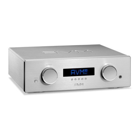
AVM PA 30.3 User manual

Operating Instructions
PA 30.3


Declaration of conformity (for EC only)
We herewith confirm, that the unit to which this manual belongs fulfils the EC rules necessary
to obtain the sign
the necessary measurements were taken with positive results.
AVM Audio Video Manufaktur GmbH
Daimlerstraße 8
D-76316 Malsch
Germany
www.avm.audio

Welcome!
We are pleased you have chosen an audiophile masterpiece of the AVM30 series and thank you
for your trust. With the PA 30.3 preamplifier you own an extraordinary HiFi component with
excellent sound and a wide range of functions. In the following, we would like to explain the use
of your PA 30.3 in a comprehensive way and therefore ask you to take a little time to study this
manual in detail.
Should you have any questions which we have not been able to answer with this manual, please
contact your dealer or distributor who will be able to configure the unit according to your needs
and personal requirements and also give you instructions for daily use.
Udo Besser – AVM Owner & General Manager

Table of contents
1!Getting started.................................................................................................................... 6!
1.1!What’s in the box?........................................................................................................ 6!
1.2!Control and operating elements................................................................................... 6!
1.3!Pin assignments ........................................................................................................... 7!
1.4!Installation and cooling................................................................................................. 8!
1.5!Connection to mains .................................................................................................... 8!
1.6!Connecting analogue signal sources ........................................................................... 8!
1.7!Connecting digital signal sources ................................................................................ 9!
1.8!Connecting a power amplifier ...................................................................................... 9!
1.9!Installing the Bluetooth antenna................................................................................... 9!
1.10!Connecting a recording device .................................................................................... 9!
1.11!AV Pass Through (Home Theater Loop)....................................................................... 9!
1.12!Connection of switching voltages .............................................................................. 11!
1.13!Connecting headphones ............................................................................................ 11!
1.14!RC 3 remote control ................................................................................................... 11!
2!Operation .......................................................................................................................... 13!
2.1!First power on / self test............................................................................................. 13!
2.2!Switching device on / off ............................................................................................ 13!
2.3!Input selection ............................................................................................................ 13!
2.4!Bluetooth .................................................................................................................... 13!
2.5!Volume settings .......................................................................................................... 14!
2.6!Input sensitivity (level adjustment).............................................................................. 14!
2.7!Balance....................................................................................................................... 14!
2.8!Sound settings (Bass/Treble) ..................................................................................... 15!
2.9!Reset (factory settings)............................................................................................... 15!
2.10!Automatic power-off................................................................................................... 15!
2.11!Demo-Mode ............................................................................................................... 16!
3!Appendix ........................................................................................................................... 17!
3.1!Care of the housing .................................................................................................... 17!
3.2!Troubleshooting.......................................................................................................... 17!
3.3!Conditions of warranty (EC only)................................................................................ 18!
3.4!Specifications ............................................................................................................. 19!

6
1 Getting started
1.1 What’s in the box?
• PA 30.3 preamplifier
• Bluetooth antenna
• Power cable
• RC 3 remote control
NOTE: After unpacking, please check the scope of delivery to ensure that all parts have been
supplied and are undamaged. In case the original packing has already been opened, please
contact your local dealer. Often, your dealer prepares your new device prior to delivery to adapt
and change the configuration to your personal needs.
1.2 Control and operating elements
The numbers in the drawings below mark the control elements. They refer to the numbers in
the text, where the operation of the unit is described.
1 Control LED
2 POWER button (on / off)
3 SOURCE selector
4 BASS button
5 TREBLE button
6 Display
7 LEVEL button
8 BALANCE button
9 VOLUME selector
10 Headphone output

7
11 Ground connection for record player
12 Phono MM / MC selector switch
13 Configuration port (Firmware)
14 LOAD Input for phono impedance (MC)
and capacity (MM) adjustment
15 Phono input
16 Bluetooth antenna socket
17 High-level analogue inputs CINCH
18 USB B input
19 High-level analogue input XLR
20 Digital inputs (COAX, OPTO)
21 IR input for external sensor
22 Trigger outputs (TRIGGER OUT)
23 Analog recorder output (FIX)
24 Analog preamplifier output RCA
25 Analog preamplifier output XLR
26 Mains switch
27 Mains connector
1.3 Pin assignments
1.3.1 Assignment XLR Input (19) and Output (25)
1) Ground (GND)
2) POS (+)
3) NEG (-)
1.3.2 Pin assignment of the 3.5 mm jack output for external trigger signals (22)
a) Ground (GND)
b) Trigger signal (+5V)

8
1.3.3 Pin assignment of the 3.5mm stereo jack input for external infrared
receivers (21)
c) Ground
d) IR signal (from receiver)
e) +5V (Supply for external receiver)
1.4 Installation and cooling
The unit can become hot depending on demanded output power or environmental temperature.
Therefore, it is important, that the cooling air can flow unhindered into the air inlet in the bottom
and flow out through the holes in the rear panel. Direct exposure to sunlight is not
recommended because this will heat up the unit and may cause unwanted malfunctions.
1.5 Connection to mains
Connect the supplied power cable to the power connection (27) and a power outlet. The blue
operation indicator LED (1) starts to light up and goes out as soon as the unit is switched on
with the on/off button (2) and the display (6) lights up.
NOTE: Please leave the unit switched off for the time being (power switch (26) in zero position),
until you have established all cable connections to the rest of the unit.
NOTE: Always disconnect the PA 30.3 completely from the power supply when you make
changes to the cabling.
1.6 Connecting analogue signal sources
High-level sources
To connect analog signal sources, connect them via suitable cables to the balanced XLR input
(19) or the unbalanced RCA inputs (17) at the rear of the unit. For the RCA inputs, the left
channel is connected to the upper row (white), the right channel to the lower row (red).
Phono
Connect your turntable to the ground terminal (11) and the phono input (15). Depending on the
design principle of the pick-up system used, use the Phono MM / MC selector switch (12) to
choose the correct setting for your pick-up.

9
If your pickup system works according to the MM or MC principle, please refer to the
corresponding documentation. Depending on the desired terminating capacitance (MM) or
terminating resistor (MC) of your pickup system, it can either be connected only to the phono
input (15) or additionally adjusted via the LOAD input (14). For this purpose, a corresponding
pair of plugs is plugged into the LOAD input for phono impedance (MC) and capacity (MM)
matching (14).
1.7 Connecting digital signal sources
Connect digital signal sources to either the coaxial or the optical digital input (20) using a
suitable cable. The COAX input is connected to the source devices via 75 Ohm cables, the
OPTO input via optical fiber.
NOTE: Please note that to play back a digital signal, a corresponding sound source with a
compatible input signal must be present. Otherwise the message NO DIG SIGNAL will appear
on the right side of the display instead of a volume value.
1.8 Connecting a power amplifier
To connect the PA 30.3 to a power amplifier, use the analog preamplifier output RCA (24) or
XLR (25). The power amplifiers can also be easily connected via the PA 30.3 can be switched
on remotely (see section Error! Reference source not found.).
1.9 Installing the Bluetooth antenna
For optimal use of the integrated Bluetooth functions, the Bluetooth antenna included in the
scope of delivery must be connected to the antenna connector (16) on the back of the device.
Please make sure that the antenna is aligned straight when screwing it on. Only then angle the
antenna to the desired position.
1.10 Connecting a recording device
The inputs of a recording device are connected to the analog recording output FIX (23). The
outputs of the recording device can again be connected to one of the analog high-level inputs
of the PA 30.3 (17, 19).
1.11 AV Pass Through (Home Theater Loop)
For integration of the PA 30.3 into a home cinema system, the PA 30.3 offers an AV Pass
Through function for all high-level inputs (17,19). If this function is activated, the input signal is
played back with a fixed level.

10
NOTE: In addition to the volume control (see section 2.5), the options for adjusting the input
sensitivity (see section 2.6), the balance (see section 2.7) and all sound settings (see section
2.8) of your PA 30.3 are disabled.
1.11.1 Activating the AV Pass Through function
To activate the AV Pass Through function for a high-level input (17,19), first select the desired
input with the source selector (3) in normal operating mode. Then switch the unit to stand-by
mode with the power button. Then keep the LEVEL button (7) pressed while switching on the
unit with the on/off button (1). Wait a short moment until the starting process is completed.
During the startup process, the name of the selected input is shown on the left side of the
display and a hint to the selected mode is shown on the right side.
FIX = AV Pass Through function is activated (fixed output level)
VAR = AV Pass Through is disabled (variable output level)
To activate the AV Pass Through function for another high level input (17,19), select the desired
input with the source selector (3) and repeat the procedure described above.
NOTE: When the AV Pass Through function is activated, the right part of the display shows
FIX instead of a volume value. Please note that when the AV Pass Through function is
activated, the volume control (9), BASS button (4), TREBLE button (5), LEVEL button (7) and
BALANCE button (8) have no function. When one of these controls is pressed, the FIX indicator
flashes briefly - but the corresponding function is only available again after deactivating the AV
Pass Through function (see following section).
1.11.2 Disabling the AV Pass Through function
The AV Pass Through function remains active even after the power is turned off for a selected
high-level input. To deactivate the AV Pass Through function, first select the desired high-level
input with the source selector (3) in normal operating mode. Then switch the unit to stand-by
mode with the power button. Now hold down the LEVEL button (7) while you switch on the unit
with the on/off button (1). Wait a short moment until the starting process is completed. During
the startup process, the name of the selected input is shown on the left side of the display and
a hint to the selected mode is shown on the right side. When the display VAR appears instead
of FIX, the AV Pass Through function is disabled for the selected high-level input.
To deactivate the AV Pass Through function for another high-level input, select the desired
input with the source selector (3) and repeat the procedure described above.
NOTE: To deactivate the AV Pass Through function of several high-level inputs with one
keystroke, you can also use the RESET function (see section 2.9). However, please note that
a reset will reset the entire device to its factory settings.
11
1.12 Connection of switching voltages
If a connected power amplifier is equipped with a trigger input, you can connect the switching
signal of the PA 30.3 (TRIGGER OUT) to one of the two switching outputs (22). This allows a
comfortable remote switching of power amplifiers or subwoofers. Please refer to section 1.3
for details on the control socket assignment.
1.12.1 AIR Trigger (AVM Intelligent Remote)
If you have connected a compatible AVM power amplifier model of the MA or SA series as
power amplifier, it can be switched on and off from your PA 30.3 using the RCA or XLR cable
connected to one of the two analog outputs (FIX or PREAMP OUT). You do not need a
separate control cable for this. Please refer to the corresponding documentation regarding
the operating mode setting of your power amplifier.
1.13 Connecting headphones
The PA 30.3 preamplifier is equipped with a 6.3 mm jack socket for connecting headphones
(10). Please note that the preamp outputs RCA (24) and XLR (25) are deactivated as long as
headphones are connected. The recording output FIX (23) remains active.
1.14 RC 3 remote control
The included RC 3 remote control made of aluminium allows you to control your PA 30.3
comfortably. The ON and OFF buttons are responsible for all AVM devices of a system and
switch them on and off together.
As an alternative to the RC 3 remote control supplied, you can also use the models RC 8 or RC
9 from AVM. These two remote controls allow you to control a wider range of functions and are
available from your dealer for an additional charge.
The keys < INPUT > are used to select the input of an available source, which is shown on the
display of the PA 30.3.
Use the < VOLUME > buttons to adjust the desired output volume of the PA 30.3. Further
buttons such as < STATION >, < SKIP >, STOP, PLAY serve to control further AVM
components. For example, the STOP, PLAY, and < SKIP > buttons enable control of a CD
player. The PLAY key switches between PLAY and PAUSE when pressed several times - the
STOP key ejects the CD when pressed several times. The buttons < SKIP > switch to the next
/ previous track on a CD when pressed briefly - when pressed longer, the search is accelerated
through the current track.

12
Please note the following if the remote control does not work properly: Always hold the remote
control with the front end facing the device you want to operate. If the remote control is placed
too far away from the device to be controlled, or if the batteries are dead or objects are placed
between the remote control and the device to be controlled, the remote control may not
function properly.
1.14.1 Battery replacement
Bottom of the RC 3 remote control
If the range of the remote control decreases significantly, new batteries must be installed.
Remove the six screws on the bottom of the remote control marked with arrows (ATTENTION:
do not open the two middle screws without arrow marking!) Now turn the remote control over
and take out the bottom with the printed circuit board. Now remove the used batteries and
replace them with two new ones of the same type (Lithium button cell 3V, type CR2032). Make
sure that the polarity of the batteries is correct when inserting them (marking "+" upwards),
otherwise the electronics may be damaged.

13
2 Operation
2.1 First power on / self test
When the PA 30.3 is switched on for the first time, a self-test is performed first, provided that
the unit has been completely disconnected from the power supply via the power switch (26).
The unit checks configuration and functionality of the installed components and then goes into
stand-by mode. This process may take a few seconds.
2.2 Switching device on / off
With the on/off button (2) you can switch between operation and stand-by mode. In stand-by
mode, the display is dark and the operation indicator LED (1) lights up. As soon as the machine
is in operation, the operation indicator goes out and the display (6) is activated.
ATTENTION: The device is not completely disconnected from the power supply in stand-by
mode. For complete disconnection from the power supply, press the power switch (26) at the
rear of the device or pull the power cable out of the cold appliance connection (27).
2.3 Input selection
The input selection is done by turning the INPUT source selector (3). Available are one phono
input (15), two analog high-level inputs CINCH (17), one analog high-level input XLR (19), two
digital inputs OPT, COAX (20), one USB B input (18), and one channel for receiving a high-
resolution Bluetooth signal.
The currently selected program source is shown in the display (6) on the left side (e.g. IN RCA1,
IN RCA2, IN XLR, BLUTOOTH, DIG USB, DIG COAX, DIG OPTO, IN PHONO).
2.4 Bluetooth
The integrated Bluetooth function enables the wireless transmission of a music signal from a
Bluetooth-enabled playback device such as a smartphone, tablet or computer. In order to use
the Bluetooth function, an appropriate playback device must first be connected to your PA
30.3. This process is also called Pairing and is done in no time at all.
First select the Bluetooth input with the source selector (3). The display shows ON AIR in the
lower left corner, indicating that the Bluetooth input is active and ready for operation. Then
navigate to the Bluetooth menu of your player. Make sure that the Bluetooth function is
activated and start the search process for available Bluetooth devices in your vicinity. If in
doubt, please refer to the documentation of the respective manufacturer for details on how to
operate the Bluetooth settings on your playback device.

14
Now select the PA 30.3 ("AVM-30.3") as the device for audio playback and wait a short moment
until the connection is established. The display CONNECTEDon the lower left side of the
display (6) indicates a successful connection of both devices. In this state the device is locked
for further playback devices so that the already started music playback cannot be interrupted
by another Bluetooth playback device. To start music playback from another Bluetooth device,
the Bluetooth connection to the PA 30.3 must first be interrupted on the current device. The
message ON AIR appears again in the lower left corner of the display. You can then pair your
PA 30.3 with another device.
NOTE: If the Bluetooth input is not selected, the integrated Bluetooth module is disconnected
from the power supply. The antenna does not emit any signal in this state. This prevents
possible interference. As soon as the Bluetooth input is selected again, your amplifier
automatically reconnects to the last connected Bluetooth device.
2.5 Volume settings
Use the VOLUME rotary control (9) to adjust the volume. The currently selected volume value
is shown on the right side of the display (6) with a numerical value from 0 to 99.5. If FIX is
displayed at this point, the AV Pass Through function is activated for the selected input and
the volume control is disabled. For details on the AV Pass Through function, refer to section
1.11 AV Pass Through (Home Theater Loop).
2.6 Input sensitivity (level adjustment)
Often the signal sources present in a hi-fi system have different levels. When switching between
them, this results in a volume jump, which can be prevented by individually adjusting the input
sensitivity of the inputs. Select a local digital or analog input or BLUETOOTH with the source
selector (3) and adjust the monitoring volume to a comfortable level with the volume control (9).
Check by switching to other inputs whether the levels are nearly identical. If there is a
difference, press and hold the LEVEL button (7). By turning the volume control (9) you can now
adjust the level of the selected input in a range of -9.5 to +10.0 dB. After releasing the LEVEL
button (7), the sensitivity value for the selected input will be stored and the unit will return to its
normal operating state. Repeat this procedure until all levels are approximately identical.
NOTE: During level adjustment, all remote controls are disabled. While you are making menu
settings on the main unit, the supplied RC 3 remote control cannot be used.
2.7 Balance
By pressing and holding the balance button BAL (8) the right-left balance of the output signal
can be adjusted globally for all input channels by means of the volume control (9). The current
setting is shown in the display (6) on the right side while the BAL button is pressed. As soon
as you release the button, the set value is stored and the unit returns to its normal operating
state.

15
2.8 Sound settings (Bass/Treble)
By pressing and holding the balance button BAL (8) the right-left balance of the output signal
can be adjusted globally for all input channels by means of the volume control (9). The current
setting is shown in the display (6) on the right side while the BAL button is pressed. As soon
as you release the button, the set value is stored and the unit returns to its normal operating
state.
The integrated tone control electronics for adjusting the bass or treble components of the PA
30.3 is activated as soon as you make a setting under BASS or TREBLE. If a neutral setting
(BASS = 0, TREBLE = 0) is selected, the tone control electronics will remain deactivated until
one of these parameters is changed. The display will show TONE ON when the tone control is
activated and LINEAR when it is deactivated.
2.9 Reset (factory settings)
The RESET option offers you the possibility to reset the device to the original delivery state
and thus to all factory settings. The following settings are reset in the course of a RESET:
ü Individual input sensitivities (level settings). For details see section 2.6.
ü Cross-channel adjustments of the right-left balance (see section 2.7) and the bass/treble
sound settings (see section 2.8)
ü AV Pass Through function for high level inputs (17,19) (see section 1.11)
ü AV Pass Through Funktion für Hochpegel-Eingänge (17,19) (siehe Abschnitt 1.11)
To perform a RESET, switch off the device with the mains switch (26) on the back. Then press
and hold the TREBLE button (3) and the LEVEL button at the same time and switch the unit
on again with the power switch (26) on the back. Now press the BAL button (8) to perform the
RESET or BASS (4) to cancel the process. Wait until the unit changes to standby mode. Your
PA 30.3 integrated amplifier is now reset to its factory settings.
2.10 Automatic power-off
The PA 30.3 integrated amplifier is equipped with an energy-saving automatic power-off. If no
music is played for a period of 20 minutes or no function is activated on the unit, the PA 30.3
automatically switches to standby mode. By pressing the on/off button (2) the unit can of
course be switched on again at any time.
The automatic switch-off can be deactivated or reactivated as follows: Switch off the unit with
the rear power switch (26). Keep both keys BASS (4) and TREBLE (5) pressed and switch on
the unit with the rear power switch (26). Depending on the selected setting, the display appears:
AUTO OFF ACTIVE or AUTO OFF NOT ACTIVE. You can change the setting by repeatedly
pressing the LEVEL button (7) and then permanently store it by pressing the POWER button
(2).

16
NOTE: Please note that disabling the auto power off feature will result in higher power
consumption, as the device will remain in operation even if you do not listen to music with it for
a longer time.
2.11 Demo-Mode
The PA 30.3 integrated amplifier is equipped with a so-called Demo Mode. This demo mode is
primarily intended for specialist dealers to show the respective features of the unit in the form
of a 'slide show' on the display (6) while the unit is presented, for example, in a store or
exhibition.
To activate the Demo Mode, first switch off the device via the power switch (26). Then keep
both buttons LEVEL (7) and BAL (8) pressed while switching on the device via the power switch
(26).
The Demo Mode is deactivated by switching off the mains voltage via the mains switch (26).
As soon as you switch on the unit again, it will return to normal operating mode.

17
3 Appendix
3.1 Care of the housing
The surface and the printing on the housing are largely scratch-resistant. The PA 30.3 can be
cleaned with mild soapy water or a gentle glass cleaner and a soft duster.
ATTENTION: Do not allow any liquid to enter the inside of the housing during cleaning. In
addition, for safety reasons, the power cord should be disconnected before damp wiping. Do
not use solvents or abrasive cleaners that could damage the surface or printing on the housing.
3.2 Troubleshooting
Often, supposed defects can be traced back to operating errors. Sometimes other components
connected to the PA 30.3 are also responsible for a malfunction. Before you contact your dealer
or us about a defect, please check the following list to see if you can correct the malfunction
yourself, e.g. by resetting the device to the factory settings - see RESET in section 2.9.
1. No music playback
a) Accidentally switching to stand-by mode via remote control. Press the on/off button (2).
b) If the display is dark and the operation indicator LED (1) is not lit, the mains fuse may be
defective. Since this is usually caused by a defect in the power supply unit or amplifier
electronics (e.g. due to a lightning strike), please contact your dealer.
c) The unit has automatically gone into standby mode after a period of 20 minutes without
playing music or activating a function on the unit (see section 2.10)
2. The device switches off during operation
a) If no music is played for a period of 20 minutes or if a function on the unit is activated, the
automatic switch-off function of the unit is activated and the unit switches automatically to
standby mode (see section 2.10 Automatic switch-off).
b) One of the protective circuits of the unit (e.g. overload, overtemperature, short circuit) has
responded. Please contact your specialist dealer.
3. Remote control without function
a) The batteries of the remote control are empty. Please replace the batteries (see section
1.14.1)
b) There is no direct connection between the remote control and the device or the distance is
too great.

18
3.3 Conditions of warranty (EC only)
If despite expectations a defect occurs that cannot be repaired by yourself or your dealer, we
undertake the repair of your unit free of charge for up to three years from date of purchase. The
warranty covers the costs of material and working time, transport costs are to be borne by the
owner.
Provisions for this warranty are:
• The unit must have been purchased from an authorised dealer. Equipment from other
sources will not be repaired, not even at charge.
• The warranty registration card, together with a copy of the bill of sale, must be received
by us within four weeks of the date of purchase.
• The defect must not have been caused by improper handling or misuse.
• Return the unit to us only in its original packing. If this is not possible, we are entitled to
refuse acceptance. We will not assume responsibility for transport damage under any
circumstances.
• A short description of the defect is to be included with the returned unit.
• In cases of doubt we reserve the right to request a copy of the bill of sale.
• We also reserve the right to levy a handling charge for items returned without good or
valid reason, or if the unit proves to be not defective.
NOTE: If you are returning the unit from a country other than Germany you should ensure that
correct export documents are obtained. We cannot accept any charges for costs arising from
improper or incomplete export documentation.
If you have purchased your unit from a dealer outside Germany, please refer to him or the
relevant importing firm to process the warranty.

19
3.4 Specifications
3.4.1 Analog inputs & outputs
Input sensitivity RCA 62 mV +/-9,5 dB, adjustable
Input sensitivity XLR 125 mV +/-9,5 dB, adjustable
Input sensitivity Phono MM 0,5 mV +/-9,5 dB, adjustable
Input sensitivity Phono MC 0,05mV +/-9,5 dB, adjustable
Signal-to-noise ratio RCA (500 mV) 98dB / 101dB (A)
Signal-to-noise ratio XLR (1 V) 98dB / 101dB (A)
Signal-to-noise ratio Phono MM (5 mV) 79dB / 83dB (A)
Signal-to-noise ratio Phono MC (0,5 mV) 69dB / 72dB (A)
Input impedance RCA 6,8 kΩ
Input impedance XLR 40 kΩ
Input impedance Phono MM 47 kΩ//200pF, adaptable via LOAD sockets
Input impedance Phono MC 1 kΩ//1000 pF, adaptable via LOAD sockets
Output impedance LINE OUT 1 kΩ
Output impedance PRE OUT RCA 50 Ω
Output impedance PRE OUT XLR 110 Ω
Output impedance Headphones 50 Ω
THD (Ua = 1V) 0,0013%
Frequency Response RCA, XLR <10 Hz - > 150 kHz
Frequency Response Phono RIAA +/- 0,3 dB
Maximum output voltage RCA 3,4V
Maximum output voltage XLR 3,4V (optional 6,8V)
Maximum output voltage Headphones 12V
3.4.2 Digital inputs & outputs, Bluetooth
Sampling frequency SPDIF 32 to 192 kHz / 24 Bit (opt. up to 96/24)
Sampling frequency USB 32 to 48 kHz
Frequency Response SPDIF <20 - >50 kHz
Frequency Response USB <20 - 24 kHz
Input format DIG IN OPT SPDIF, linear PCM 32 - 96 kHz / 16 - 24 Bit
Input format DIG IN COAX SPDIF, linear PCM 32 - 192 kHz / 16 - 24 Bit
USB input Linear PCM to 48 kHz / 16 Bit
Input impedance DIG IN COAX 75 Ω
Input impedance DIG IN COAX According to IEC 908

20
Bluetooth Standard v4.2
Codecs: SBC, MP3, AAC, FastStream, aptX
Samplerate (adaptive): Max 96 kHz/16Bit
Frequency Response: 20 Hz – 20 kHz
Signal-to-noise ratio: 96 dB
3.4.3 Miscellaneous
Supply voltage 100 - 240V / 50 - 60 Hz
Power consumption 7 W
Power consumption stand-by 0,3 W
Trigger Out Voltage +5 V
Dimensions (B x H x T) 430 mm x 110 mm x 345 mm
Weight 7 kg
Changes reserved without notice.
2020/09/23.
Table of contents
Other AVM Amplifier manuals

AVM
AVM EVOLUTION MA3.2S User manual

AVM
AVM OVATION SA8.2 User manual

AVM
AVM OVATION MA 8.3 User manual

AVM
AVM INSPIRATION SD 2.2 User manual

AVM
AVM EVOLUTION A3.2 User manual

AVM
AVM OVATION PH 8.3 User manual

AVM
AVM A 30.3 User manual

AVM
AVM EVOLUTION PA3.2 User manual

AVM
AVM OVATION SD 6.2 User manual

AVM
AVM OVATION MA 6.3 User manual