AVM OVATION PA 8.3 User manual

OVATION PA 8.3
Operating Instructions

Declaration of conformity (for EC only)
We herewith confirm, that the unit to which this manual
belongs fulfills the EC rules necessary to obtain the sign
the necessary measurements were taken with positive
results.
AVM Audio Video Manufaktur GmbH
Daimlerstraße 8
76316 Malsch
Germany
www.avm.audio
info@avm.audio

1. Getting started
1.1 What’s in the box? ... 1
1.2 Control and operating elements ... 2
2. Basic operation
2.1 First operation / self test ... 8
2.2 Selecting a sound source ... 10
2.3 Volume setting ... 10
2.4 Analog inputs ... 11
2.5 Digital Inputs ... 12
2.6 Phono Input ... 14
2.7 Phono Settings ... 15
2.8 FM-Tuner ... 18
2.9 FM Tuner Settings ... 20
2.10 Advanced FM Tuner Settings ... 22
2.11 Sound settings ... 23
2.12 Remote Control ... 27
3. Appendix
3.1 Personal Setup ... 29
3.2 Reset (Factory Settings) ... 33
3.3 Cleaning ... 34
3.4 Troubleshooting ... 34
3.5 Conditions of warranty (EC only) ... 36
3.6 Specifications ... 37


OVATION PA 8.3 | 1 |
CHAPTER
1Getting started
1.1 What’s in the box?
• PA 8.3 Preamplifier
• Power cord (in some countries)
• RC 3 remote control
After unpacking, please check the scope of delivery
to ensure that all parts have been supplied and are
undamaged. In case the original packing has already
b ee n o p e n e d , p l e a s e c o nt a c t y o u r l o c a l d e a l e r.
Often, your dealer prepares your new device prior to
delivery to adapt and change the configuration to
your personal needs.

Getting started
OVATION PA 8.3 | 2 |
1.2 Control and operating elements
1.2.1 Front
1. Power button (on/off)
2. Source selector
3. Control LED
4. Menu buttons
5. Display
6. Volume knob
7. Headphone output (6,35mm)
1.2.2 Back plate

Getting started
OVATION PA 8.3 | 3 |
CAUTION
Pl ea se u se o nly Sl o t 8
t o i n s t a l l t h e I N P U T
T O N E c a r d ( 9 ) . T h e
Slots 1-7 may be alloca-
ted wit h all other inpu t
c a r d s : I N P U T, T U N E R ,
PH O N O M M / M C , D I G I -
TAL IN (8).
8. Slot 1-7 for all input cards (except INPUT
TONE)
9. Slot 8 only for INPUT TONE card
10. Slot 9-11 for all output cards
11. Mains connector
12. Mains switch
13. Trigger outputs (TRIGGER OUT)
14. Input for external IR receiver (EXT IR)
15. Phase LED
16. Link-Port
17. Configuration port (Firmware)
1.2.3 Pin assignment: XLR
XLR input (left)
XLR output (right)
1. Ground (GND)
2. Non-inverting input/output POS (+)
3. Inverting input/output NEG (-)

Getting started
OVATION PA 8.3 | 4 |
1.2.4 Pin assignment: Trigger outputs
Pin assignment of the 3,5mm jack output
for external trigger signals(13)
a) Ground (GND)
b) Trigger signal (+5V)
1.2.5 Pin assignment: Input for external IR receiver
Pin assignment of 3,5mm stereo jack input for
external IR receiver (14)
c) Ground (GND)
d) IR signal
e) +5V

Getting started
OVATION PA 8.3 | 5 |
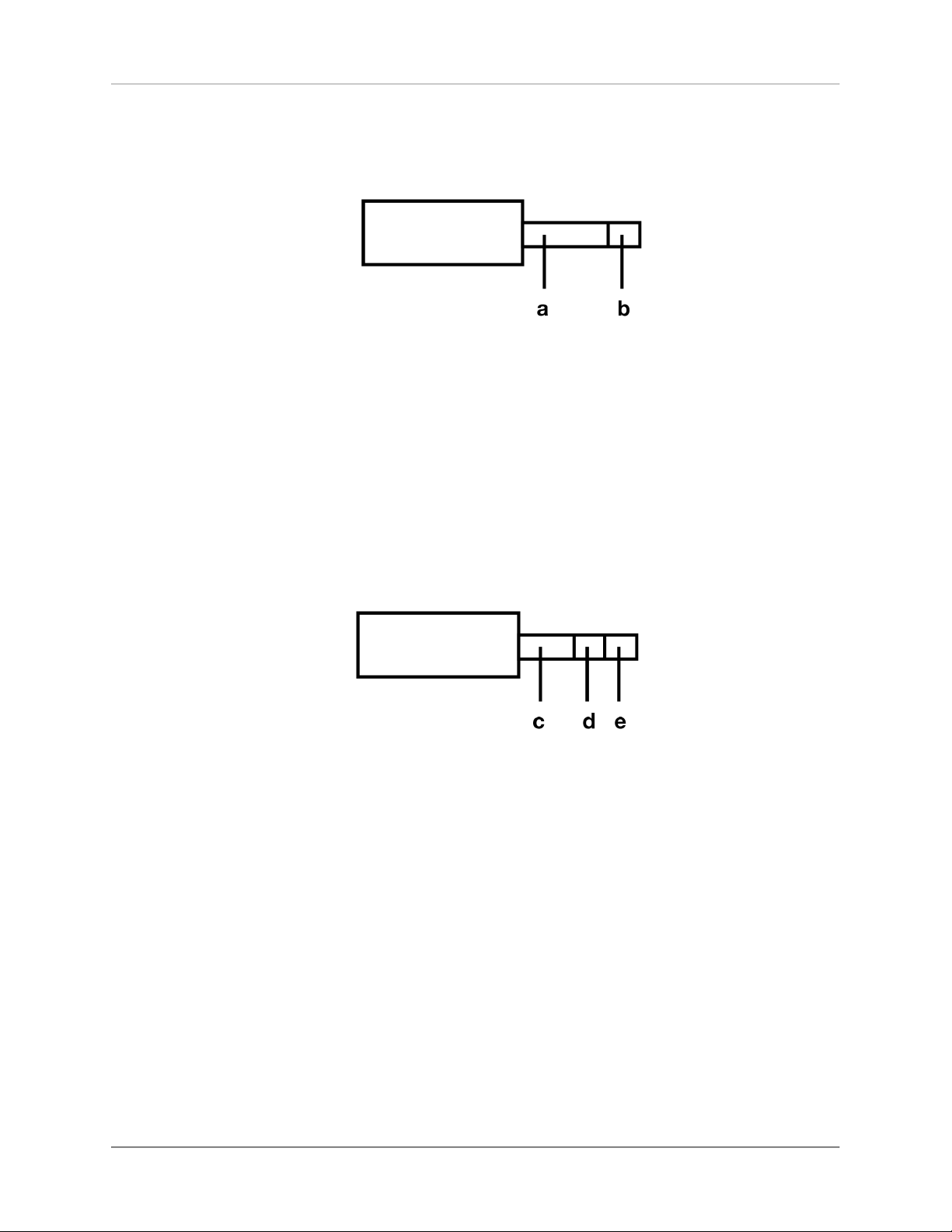
1.2.6 Assembly of input and output cards
CAUTION
P l e a s e ma k e s u r e t h e
mai n s p l u g i s rem ov e d
b e f o r e y o u o p e n t h e
unit. Pl ug-i n cards may
n e v e r b e i n s t a l l e d o r
re m ove d whil e th e uni t
is p o we red on . In c ase
o f a n y d o u b t , p l e a s e
con s u lt yo ur l oca l dea-
l e r t o a s s i s t y o u w i t h
t h e a s s e m b l y of i n o u t
and output cards.
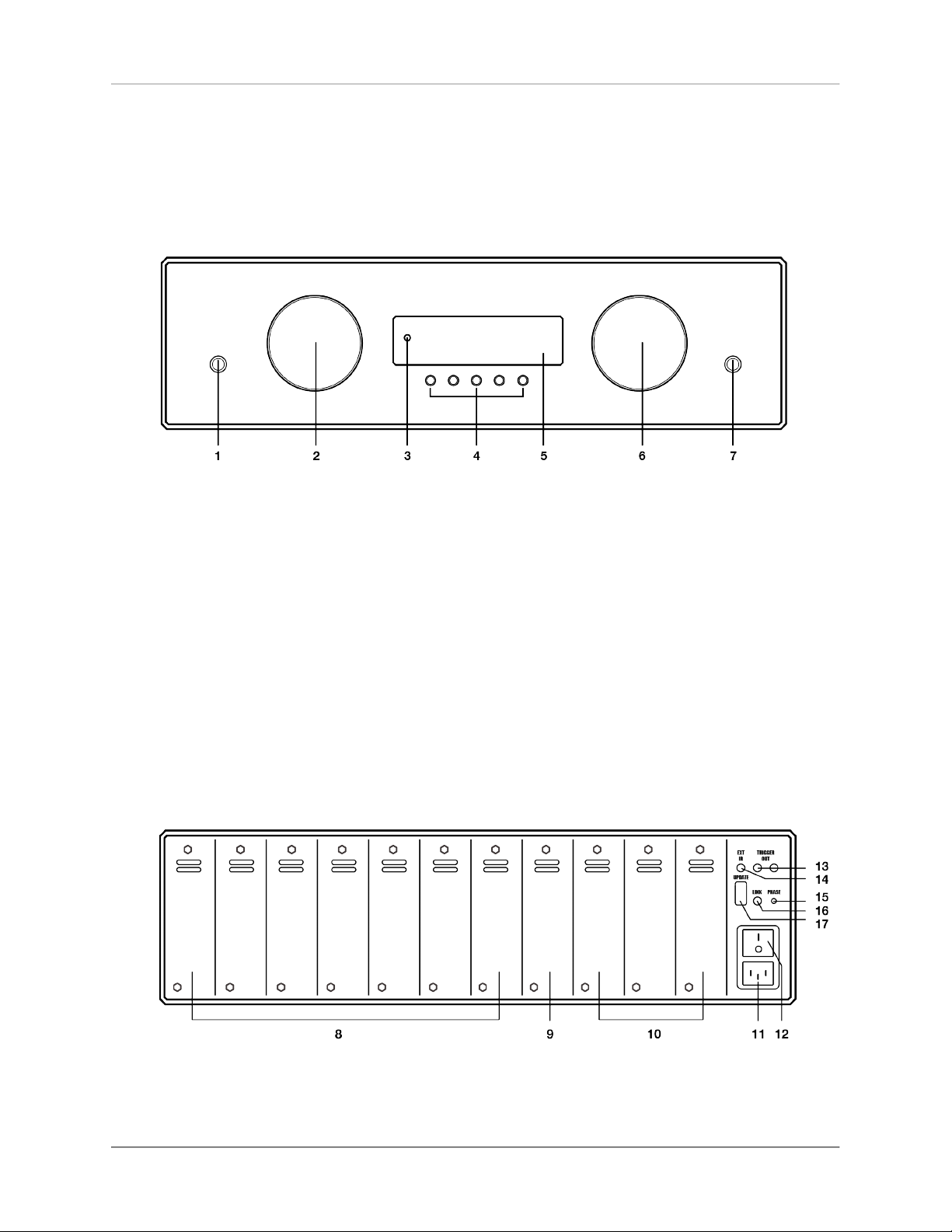
At the back of the PA 8.3, there is a total of 11 slots
which may be allo ca t e d with optionally ava ilab le
inp u t a nd ou tp ut c ar d s ( s l ot -in mod u les) . T h es e
slots are counted from the left to the right (see sec-
tion"B a ck plate" on pa ge 2). Existing p lug-in cards
can be in almost any order. Unused slots come with
a blanking plate covered.
The nature of all plug-in cards is identical (width
of the cover plate, position of the plug). Neverthe-
less, to ensure correct operation of the PA 8.3, some
placement rules must be observed:
NOTE
Ke ep th e un it s witched
o f f u n t i l a l l a u d i o
connections are made.
1. Input cards can be placed in any order to the
slots 1-7 (8).
2. The INPUT TONE card with integrated sound
control may exclusively be installed in slot 8
(9).
3. Output cards are installed in slots 9-11 (10).
Please n o te: Each time t he device i s powered on
with the power switch on the rear side (12), the unit
goes through a hardware test and verifies the confi-
gura tion and functionality of the input and o utput
cards used. The current status od the test is shown
on the display (5). If the module is placed incorrec-
tly or in the wrong position (e.g. input module in the
position of an output module), the hardware test will
be aborted and an error message is displayed.

Getting started
OVATION PA 8.3 | 6 |
1.2.7 Connection of sound sources
An alog an d di g i t a l sour c es are co nn ecte d to t he
inputs of the installed input cards of the PA 8.3. The
left channel is connected to the white marked RCA
input, the right one channel at the red marked. At
the XLR inputs, the upper port is intended for the left
channel (L), the lower one for the right channel (R).
1.2.8 Connection of power amplifiers
NOTE
M a k e s u r e w h e n
co nnec ti ng XLR c ab les
t h a t c o r r e c t w i r i n g o f
t h e X L R p l u g i s u s e d
(se e sec tion"P in as s ign-
ment: XLR" on page 3).
Use suitable cables to conne ct your power amp li-
fi er ( s ) to th e c o n ne ctor s of t he in s t all ed ou t p ut
cards in the slots 9-11 (see section"Back plate" on
page 2).
The left channel transitions to the white marked
RCA, the right channel to the red marked RCA.
For the XLR outputs, the upper port is for the left
channel (L), the lower connection for the right chan-
nel (R).
1.2.9 Remote activation of power amplifiers
1.2.9.1 Remote activation of power amplifiers with
analog trigger input
If your amplifier is equipped with a trigger input, the
PA 8.3 can remotely turn it on. To do th is, connect
one of the two trigger outputs of the PA 8 . 3 (1 3)

Getting started
OVATION PA 8.3 | 7 |
with a trigger input of your amplifier. For a correct
p i n a s s i g n m e n t , p l e a s e r e f e r s e c t i o n , s e e s e c -
tion"Pin assignment: Trigger outputs" on page 4.
1.2.9.2 Remote activation of latest generation AVM
amplifiers
If you have an AVM amplifier of the latest genera-
tion connected (E VOLUTION MA 3.2, SA 3.2, OVA-
TI O N M A 6 / 8 . 2 , SA 6 / 8 . 2 ) , i t w i l l a ut o m a t i c a l l y
turned on, provided the respective mode is activated
at your AVM amplifier. A connection of a separate
trigger cable (see section"Remote activation of power
amplifiers with analog trigger input" on page 6) is not
required in this case.
1.2.10 Connection of headphones
HINWEIS
Please note that all out-
p u t s i g n a l s ( 1 0 ) a r e
m u t e d as l o n g as t h e
headphone output (7) is
connected.
Through the headphone output on the front of the
unit (7), headphones with a 6,35 mm jack plug may
be connected. The volume of the headphone output
signal is regulated with the volume control (6).

OVATION PA 8.3 | 8 |
KAPITEL
2Basic operation
2.1 First operation / self test
CAUTION
If the device is too cold,
condensation water can
f o r m i n s i d e t h e u n i t .
T h i s m a y d a m a g e t h e
unit if it is s witched on
t o o e a r l y . T h e r e f o r e ,
a l l o w t h e P A 8 . 3 t o
s t a n d i n t h e l i s t e n i n g
r o o m f o r a t l e a s t o n e
hour before switching it
on so that it ca n adapt
to the current room tem-
perature.
First, press the power switch on the rear panel (12)
and a hardware test will be performed. The device
chec ks the conf i guration and fu nctional i ty of the
input and output cards used. The current status of
the hardware test is shown in the display (5 ). If a
module is not inser ted properly or in the wrong posi-
tion (for example, input module in the position of an
output module), the hardware test is aborted and a
correspond i ng error mes sage appears. Up on suc-
cessful completion of the hardware test, the device
enters standby mode.
The on / off button (1) allows you to switch bet-
ween operation and standby mode. In standby mode,
the display is dark and the control LED (3) is lit. As
soon as the device is in operation, the control LED
goes out and the display is activated.

Basic operation
OVATION PA 8.3 | 9 |
Please note: The device is not entirely disconnected
in standby mode. To disconnect completely, press
t h e m a i n s s w i t c h o n t h e re a r p a n e l ( 1 2 ) o r d i s -
connect the power cable from the mains connector
(11).
2.1.0.1 Phase LED
A glowing phase LED on the back (15) indicates an
inc or rec t phase . Th erefo re , m ak e su re the p hase
LED does not light up after switching on the device
for the first time. Otherwise change the phase posi-
tion, e .g . by tur ni n g the m ai n s plu g to the p ow e r
socket.
2.1.0.2 Tube warm-up
I f a n o p t i o n a l T U B E O U T c a rd i s in s t a l l e d , t h e
switch-on process will take about 30 seconds due to
the required tube warm-up time. Please wait until
the entire display waiting for tube warmup changes
completely from lower case to uppercase and then
goes out. The device is now ready for use.
Without a TUBE OUT card installed, the switch-on
proc es s ta ke s ap p r ox. f i ve s e con d s. T he display
shows a corresponding countdown during this time.

Basic operation
OVATION PA 8.3 | 10 |
2.2 Selecting a sound source
NOTE
I n p u t na m e s o f s o u n d
sources can be adjusted
as d esired via the p e r-
sonal setu p m enu (se e
section "Person a l Set up"
on page 29).
To sele ct a sound source, turn the source selector
(2). The selected program source is shown in large
letters on the display (5) - e.g. RCA, XLR, USB, OPTO
or C OA X. An exc e pt ion i s th e T U NER inpu t c a rd :
Here, e.g. the frequency RDS name of the currently
selected station is displayed in large letters instead
(see section "Set RDS display" on page 20).
2.3 Volume setting
To adjust the volume, use the right-hand rotary con-
t r o l ( 6 ) . T h e c u r re nt vo l u m e v a l u e i s d i s p l a y e d
numerically (0 to 99.5 dB) in large letters in the dis-
play (5).
The step size of the volume change depends on
the ro ta tion s p e e d. S l o w rotat i o n cau s es a leve l
change in steps of 0.5 dB, fast turning changes the
volume in 2 dB steps.
Please note: If an optional digital input is selected
and there is no valid digital signal, the display will
show NO DIG SIGNAL instead of a volume value. In
this state, adjusting the volume is not possible.

Basic operation
OVATION PA 8.3 | 11 |
2.4 Analog inputs
NOTE
To use an analog input,
it is necessary to install
an o p t i o na l i n p u t c a rd
(INPUT or INPUT TONE)
(see section "Assembly of
i n pu t a nd ou t p ut ca r d s "
on page 5).
To se l e ct a n ava ilable an a l og ue i np u t, p re ss t he
source selecto r sw it ch (2) unti l the desired input
name i s shown on the disp lay in large le tters (d).
Additional sound settings are available by pressing
the MENU (e) button (see section "Sound settings" on
page 23).
a) SLOT: Indicates the selected slot of an
input card (slot 1-8).
b) IN: Numeric display of the selected input on a
card, e.g. 1 for RCA, 2 for XLR. The name of the
selected input is shown in large letters below.
c) LINEAR: Sound control is deactivated.
TONE: Sound control is activated.
((see section "Sound settings" on page 23).).
d) Name of the selected input. This can be
adjusted as needed (see section "Define input
names" on page 31).
e) MENU button to select the sound settings (see
section "Sound settings" on page 23).
f) VOLUME: Volume indicator (see section "Vol-
ume setting" on page 10).

Basic operation
OVATION PA 8.3 | 12 |
2.5 Digital Inputs
NOTE
To u s e a d i g i t al in p u t ,
t h e i n s t a l l a t i o n o f a n
o p t i o n a l i n p u t c a r d
(DIGITAL IN) is required
(see section "Assembly of
i n pu t a nd ou t p ut ca r d s "
on page 5).
To select an available digital input, turn the source
selector (2) until the desired input name is shown
on the display in large letters (h). Additional sound
settings are available by pressing the MENU (l) but-
ton (see section "Sound settings" on page 23).
g) SLOT: Indicates the selected slot of an input
card (slot 1-8).
h) IN: Numeric display of the selected input on a
card, e.g. 1 for USB, 2 for OPTO, 3 for COAX 1,
4 for COAX 2. The name of the selected input is
shown in capital letters below and can be
adjusted as required (see section "Define input
names" on page 31).
i) LINEAR: Sound control is deactivated.
TONE: Sound control is activated.
j) VOLUME: Volume indicator (see section "Vol-
ume setting" on page 10).
k) CONV Menu buttons for selecting the sample
rate and the filter setting (m) - see section
"Samplerate and Filter settings" on page 13.

Basic operation
OVATION PA 8.3 | 13 |
l) MENU button to select the sound settings (see
section "Sound settings" on page 23)
PLEASE NOTE: MENU only displayed if a valid
signal is applied to the selected digital input.
m) Display of the current sample rate (NATIVE or
CNV) and the filter setting (FAST or SLOW) -
see section "Samplerate and Filter settings" on
page 13.
2.5.1 Samplerate and Filter settings
NOTE
F o r U S B , o n l y t h e
two options NATIVE
FA S T a n d N AT I V E
SLOW are available.
By pressing the two menu buttons CONV (k) once or
several ti mes, you ca n c hoose betwee n availa b le
sa mp le rate s a n d filte r s ett i ng s for the se lec t e d
digital input. The setting is saved for each individual
input until the next manual change.
N AT I V E i nd ic at es th a t t h e sa mpl e r a t e of t he
applied signal is processed directly. CNV stands for
'conversion' and means that it upsamples or down-
samples to the desired and displayed sample rate.
The filter settings FAST and SLOW can be selec-
ted according to your tonal preferences. Depending
on the signal played back , different filter settings
can produce the most preferable sound.
Technically speaking, FAST means steep filtering
at the band end with a flat amplitude response, but
with st rong ph ase rotation. By co ntrast, SLOW fil-
ters less steeply and already has a small amplitude
drop bef ore the end of the freque ncy band, but a
lowe r phase shift. The sel ect ed filter setting only
applies to the current input and remains stored even
after the device has been switched off. It c an be
changed at any time by pressing the menu buttons
CONV (k) again.

Basic operation
OVATION PA 8.3 | 14 |
2.6 Phono Input
NOTE
To use a phono input, an
o p t i o n a l l y a v a i l b a l e
p h o n o i n p u t c a r d
(P H O N O M M / M C ) i s
r e q u i r e d ( s e e s e c t i o n
"A s s e m b l y o f i n p u t a n d
outp ut cards" on page 5).
To select an available phono input, turn the source
selector (2) until the desired input name is shown
on the display in large letters (q). Setting options
(MM / M C, phono g ai n , subso n i c fil t er, e tc.) are
available by pressing the MENU button (see section
"Phono S ettings" on page 15). For more options, see
section "Sound settings" on page 23.
All settings made for the phono card take effect
imm ed iat el y. T hi s way, d i ffe re n t o ption s m ay b e
compared in real time while a record is playing.
n) SLOT: Indicates the selected slot of an
input card (slot 1-8).
o) IN: Numeric display of the selected input on a
card (in case of the phono card, only one input

Basic operation
OVATION PA 8.3 | 15 |
is available). The name of the selected input is
shown in large letters below.
p) LINEAR: Sound control is deactivated.
TONE: Sound control is activated.
q) Name of the selected input. This can be
adjusted as needed (see section "Define input
names" on page 31).
r) MENU Button to access the phono settings
(see section "Phono Settings" on page 15) and
sound settings (see section "Sound settings"
on page 23).
s) VOLUME: Volume indicator (see section "Vol-
ume setting" on page 10).
2.7 Phono Settings
A short press on the MENU button takes you to the
Phono Settings menu. The label of the same menu
key now changes to EXIT. Press the button again to
exit the menu and return to t he norma l operating
state.
Individual menu items may be selected with the
<ITEM> keys. The selected menu item is always dis-
pla ye d in t he upp er are a of the di sp l a y. U s e t he
<VALUE> keys to change the value of the selected
menu item. The settings made take effect immedia-
tely. This way, you may immediately control respec-
tive adjustments while a record is playing.
Pleas e no t e: Be s i d e s t he pho n o s et tin g s ex p-
lained below, you will find further sound settings in
t h e sa me m e n u ( s e e se c t i o n " S o u n d s e t t i n g s " o n
page 23).

Basic operation
OVATION PA 8.3 | 16 |
2.7.1 Set phono mode (MM/MC)
De p e n d i n g o n t h e c o ns t r u c t i o n p ri n c i p l e o f t h e
pickup system, use MM for electromagnetic trans-
ducers (M M = Moving Ma gne t) , or s el ect MC fo r
el e ctro dyn amic t rans ducers (M C = M oving Coil) .
Please refer to the corresponding documentation of
yo ur p i c ku p sy s te m to f i nd o u t w he th e r it wo r ks
according to the MM or MC principle.
Please note: In case the output level of your MC
system is high enough, the MM setting can also be
used. For fur ther i nforma ti on, please ref er to the
operating instructions of your turntable or pickup.
2.7.2 Set phono gain
Use the set phono gain function to adjust the gain to
match the pickup you are using. Depending on the
output voltage of the system, a setting between 43
dB and 52 dB (with MM setting) or 63 dB and 72 dB
(MC setting) may be selected.
Pleas e n o t e: Ev en w ith a ' wro ng' set ting, yo ur
phono card will not be damaged. If the gain is too
high, however, an audible overload by the pickup is
possible.Please make sure to reduce the gain in this
case.
2.7.3 Set subsonic filter
The function set subsonic filter offers you an optio-
nal subsonic filter to reduce audible rumble noise in
Table of contents
Other AVM Amplifier manuals

AVM
AVM OVATION MA 6.2 User manual

AVM
AVM EVOLUTION A3.2 User manual

AVM
AVM OVATION MA 8.3 User manual

AVM
AVM OVATION MA 6.3 User manual

AVM
AVM EVOLUTION A2 User manual

AVM
AVM OVATION PA8 User manual

AVM
AVM OVATION SA8.2 User manual

AVM
AVM OVATION A 6.2 User manual

AVM
AVM PA 30.3 User manual

AVM
AVM OVATION A 6.3 User manual