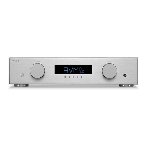
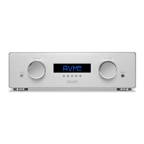
AVM OVATION A 6.3 User manual

OVATION A 6.3 / 8.3
Operating Instructions

Table of Contents
1 Getting started
1.1 What's in the box? ... 1
1.2 Packaging instructions ... 1
1.3 Contr ol and operating elements ... 1
1.4 Installation and cooling ... 4
1.5 Conn ec tion to m ains ... 5
1.6 Conn ec ting sign al sour ce s ... 5
1.7 Conn ec ting lo udspeake rs ... 6
1.8 Trig ger Outputs ... 6
1.9 Conn ec ting he adph one s . .. 7
1.10 External IR remo te co ntro l i npu t .. . 7
2 Basic op eration
2.1 First operation / self test ... 9
2.2 Switc hing on / stand by ... 9
2.3 Sele cti ng a signal source ... 10
2.4 Volume ... 10
2.5 Inp ut sensitivi ty ( Leve l Setting) . .. 1 1
2.6 Di gital in pu ts ... 12
2.7 USB B input ... 13
2.8 Blueto oth ... 14
3 Advan ced Settings
3.1 Globa l Settings ... 18
3.2 Analog Line Settings (XLR/RCA) ... 21
3.3 AUTO-ON Function ... 21
3.4 Personal Setup ... 21
3.5 Set au to standby ... 24
3.6 Rese t (factory default settings) ... 24
3.7 RC 3 remote control ... 25
4 Append ix
4.1 Clean ing ... 27
4.2 Conditions of warranty (EC only) ... 27

Table of Contents

OVATION A 6.3 / 8.3 1
Ge tt i ng s t ar ted
1. Getting started
1.1 What's in the box?
• OVATION A 6.3 / A 8.3 integrated amplifier
• Power cord (i n some countries)
• RC 3 remote control
1.2 Packaging instructions
The A 6.3 / 8.3 comes in a rugged and sturd y OVATI ON f light
cas e. Please note that the bottom of the flig ht case is not
symmetrical. If you need to put the unit into the flight cas e
again, please ens ure that the unit and the flight case is cor-
rectly positione d.
1.3 Control and operating elements
The numbers in the drawings below mark the control ele-
ments. They re fer to the numbers i n the text, where the opera-
tion of t he unit is de scr ibe d.

Ge tt i ng s t ar ted
2 OVATION A 6.3 / 8.3
Fig. 1. Front
1. Power button (on/of f)
2. Source selector
3. Control LED
4. Menu keys ( a,b,c,d ,e)
5. Display
6. Volu me control
7. He adphone outp ut
Fig. 2. Real pan el

OVATION A 6.3 / 8.3 3
Ge tt i ng s t ar ted
8. Sp eaker term inals RIGHT
9. Module bay
10. Digital inputs (USB B, OPT, COAX)
11. Configu ration p or t (Firmware)
12. Connector f or external IR sen sor
13. Bluetooth antenna connector
14. Mains switch
15. Mains con nector
16. Analog inputs (RCA /CI NCH, XLR)
17. Trigger outputs
18. LINE OUT (Recording Output RCA/C INCH)
19. PRE OUT (Preamp Output RCA/CINC H)
20. PRE OUT (Preamp Output XL R)
21. Speaker terminals LEFT
1.3.1 Pin assignments
Abb . 3. Assignment of XLR conn ectors
XLR input XLR output
1) Ground (GND)
2) Non-inverting In/Output POS (+)
3) Inverting In/Output NEG (-)

Ge tt i ng s t ar ted
4 OVATION A 6.3 / 8.3
Abb . 4. Pin ass ignm ent of 3,5 mm jack outpu t f or external
trigger signals (17)
Fig. 5. Pin assi gnment of 3,5 mm jack input f or exter nal
infra red receiver (12 )
1.4 Installation and cooling
The unit can become hot depending on de manded output
power or en vironmental temperature. There fore, it is impor t-
ant, that t he cooling air can fl ow unhindered into the ai r inlet
in the bottom and flow out through the holes in the rear panel.
Direct exposure to sunli ght is not re commended becaus e this
will heat up th e un it.
a) Ground (GND)
b) Trigger signal (+5V)
c) Masse (GND)
d) IR-Signal
e) +5V

OVATION A 6.3 / 8.3 5
Ge tt i ng s t ar ted
1.5 Connection to mains
Con nect the unit to the mains outlet (15) by usi ng the power
cord which is (in some countri es) deliv ered together with the
unit. Make sure that mains voltage i s according to the value
printe d on the rear panel of the amp (near mains connector).
ℹ CAUTION
Keep t he un it switched off u nt il all au di o c onn ect io ns are
made.
1.6 Connecting signal sources
You can connect up t o five an alog and five d igital li ne sources
to your A 6.3 / 8.3. Connect the outpu ts of your signal
sources to the re spective inputs of the A 6.3 / 8.3 on the rear
side of the unit (10, 16).
ANA LO G SOURCES (16): The up per row of the analog RCA /
Cinch or XLR connectors is for l eft channels (white), the lower
row is for right channe ls.
DIGITALQUELLEN (10): The COAX inputs may be connected
via 75 ohm cables, the optical inputs via op tical fibe rs to
respective source devices.
The USB Port (10) is intended for a connection to your PC or
MAC . Please note this may require a suitable driver to b e
installed on you r computer. You can down load res pect ive
audio drive rs from the AVM website via avm.audi o/d own loads

Ge tt i ng s t ar ted
6 OVATION A 6.3 / 8.3
1.7 Connecting loudspeakers
The l oudspeaker outputs A und B (8, 21) can be ind iv idually
act ivated and deactivated v ia the menu (see “Set spe akers
out A/B” on p age 20).
Use only g ood quality cables of sufficient cross section to
connect your speakers . In case of doubt, please refer to your
spe cialist de aler. Furthermore, make sure the polarity is cor-
rect when conne cti ng your speakers. The red marked output
jacks must be con nected to the re d marked s peaker termi-
nal s. Right and left channel must hav e the same polarity of
the speakers.
ℹ PLEASE NOTE
If yo u are usi ng b anana pl ugs, tighte n the out er pa r ts of t he
jacks before ins erti ng them (cloc kwise ) to avoid dist ur bing
rattling noises duri ng operation . If yo u use bare cable ends
or cable lugs, turn t he ou te r parts of the so cke ts to the left
as f ar a s possible, in ser t th e stripped cable e nds or cab le
lugs f rom bel ow into the ope nings provide d in the sp eaker
ter minals and th en tigh ten the ou ter par ts of the s oc kets by
turnin g them clo ckwise.
1.8 Trigger Outputs
If an option ally connected power amp lifier with a trigger input
is used in conj unction with your A 6.3 / 8.3, you may connect
the switching signal (TRIG GER OUT) to on e of the two trig ger
outputs (1 7). This al lows ad ditional power amplifiers or s ub-
woofers to be comfort ab ly switched on remotely. The pinning
OVATION A 6.3 / 8.3 7
Ge tt i ng s t ar ted
of the trigger outputs is describ ed in section 1. 3.1 Pin assi-
gnments .
1.8.1 AIR Trigg er (AVM Intelligent Remote)
If you are using a curren t AVM model of the MA or SA ser ies
as a separate powe r ampl ifier, th ere is no need f or an additio-
nal tri gger cable: Your separate AVM pow er amp lifier can be
com for tably switched on and off by the A 6.3 / A 8. 3 v ia a
connected audio cable (PRE XLR and PRE CINCH) without any
sound inte rfe rence.
1.9 Connecting headphones
Plug a 6.35 mm headphone connector to th e headphone jack
(7). The loudspeaker (8, 21) and pream p outputs (19,20) wil l
mut e automaticall y while a he adp hone is pl ugged in.
1.10 External IR remote control input
If your A 6.3 / A 8 .3 is i n a pos ition that is not directly visibl e
from the listening position, the RC 3 i nfrared remote control
may not work properly. In this case, you can connect an exter-
nal IR receiver to the EX T IR socket (12), ensur ing unrestric -
ted remote op erability of you r A 6.3 / A 8.3. Ple ase refe r to
your dealer for suitable IR receiver compon ents.

Ge tt i ng s t ar ted
8 OVATION A 6.3 / 8.3

OVATION A 6.3 / 8.3 9
B as ic o pe rat ion
2. Basic operation
2.1 First operation / self test
When switching on for the first time, a so-called self-test will
be performaned if the device had previously been completely
disconnected from the power supply or switched off via the
mains switch (14). The device checks the configuration and
functionality of the built-in components and then goes into
stand-by mode (if no AUTO-ON function is enabled). This pro-
cess may take a few seconds to complete.
2.2 Switching on / stand by
Using the power button (1) you can switch between on (ope-
rate) and stand by. When switched on, the display (5) lights
up and the LED (3) is off. This LED only lights up if the mains
plug is connected with the incorrect polarity and remains dark
if the polarity is correct.
2.2.1 Tube warmup (A 8.3)
Due to the warm-up phase of the integrated tube stage, the
switch-on process of the A 6.3 / 8.3 takes about 30 seconds
lon ger. Please wait until the entire reading on the display wai-

B as ic o pe rat ion
10 OVATION A 6.3 / 8.3
ting for tube wa rmu p ch an ges completely from lowe r to up per
cas e and then goes out. The dev ice is now ready for use.
ℹ CAUTION
In s tandby mod e, th e device is not comp let ely di sconnected
from the mains. To disconnect complet ely, pre ss the power
switch (14) o n t he back of the unit o r unplug t he power cord
from the mains con nector (15).
2.3 Selecting a signal source
A desired input signal can be selected with the source selec-
tor (2) on the front panel. You can choose from five analog
and five dig ital i nputs, as we ll as a Bluetooth i nput. The cur-
rent source is shown on the dis play (5).
2.4 Volume
To adjust the volume, turn the volume control (6). A resulting
volu me chang e depends on the speed of rotation. Slow turn-
ing causes a level change in steps of 0.5 dB, f ast turning
changes the volum e in larg er steps. The current se tti ng is
shown on the dis play (5) numerically (0 to 99. 5).
ℹ PLEASE NOTE
If a di gital sou rce is selected without a com pa tible s ignal
incoming, the functionality of the volu me con trol (6) and t he

OVATION A 6.3 / 8.3 11
B as ic o pe rat ion
remo te con trol is dea ctivated for safety reason s (e.g. acci-
dentally turning up th e vo lum e to ma ximu m etc. ).
2.5 Input sensitivity (Level Setting)
The level of different signal sources of ten varies by several
dBs resultin g in u npleasant increases/decre ases in volum e
when switching between inp uts. This may be avoide d by
adjusting the input sensitivity of respecting sources.
Use the source s ele ctor (2 ) to choose an analog or digital
input or BLUETOOTH and set the volume (6) to a conveni ent
level. If you now notice an unpleas ant in crease or decrease in
vol ume after switching to another local input by turni ng th e
source selector (2), press the menu button MENU unde r th e
display for more than two seconds . Now you can s witch bet-
ween different sources with the source selector (2) and
adjust the levels of your analog and digital sources i ncluding
BLUETOOTH by turnin g the volum e kn ob (6 ). The sensitivity of
each i nput can b e adjusted between -9.5 dB and + 10.0 dB.
Pressin g the menu button EXIT LVL unde r the d isplay wil l
save your setting s and br ing the u nit back to normal operating
mode.
2.5.1 Level adjustment of dig ital inputs
To adjust the i nput sensiti vity of a digital i nput, a dig ital sig-
nal must be connected to the respective inp ut. If you sel ect a
dig ital input that has no val id signal, NO DIG SIGN AL or NO
USB PLUGGE D is shown on the di splay ( 5) and the ME NU but-
ton under the disp lay leading to the sensiti vity setting menu
(se e section above) is deactivated.

B as ic o pe rat ion
12 OVATION A 6.3 / 8.3
ℹ NOTE
Infrared remote c ontrols such as the RC 3 remote control are
dis abled while the input sensitivi ty m enu is active .
2.6 Digital inputs
The digit al i nputs allow additional cu stom izations beyond the
nor mal setti ngs. Thes e are descr ibe d below.
2.6.1 Samplerate and filter settings
By pre ssing the <CONV> key once or several times or, w ith
USB <FILTER > (4), you can choose between availab le sampl e
rates and filte r settings for the selected source. The currently
set fil ter setting (SMOOTH / STEEP) and sam ple rate are
displayed at the top lef t of t he display (44. 1, 48, 88.2, 96 ,
176.4, 192, 352, 384 kHz). NAT stands for native and m eans
the applied sampl e rate of the signal i s di rectly processed
and conver ted. CN V s tands f or conver sion and me ans the
sample rate is upsampled or dow ns ampled.
ℹ PLEASE NOTE
Pl ease note that o nly t he sett ings NATIVE STEEP and NATIVE
SMOOTH are avail able if US B is sele cted.
The digital filter s etting s SM OOTH and STEEP can be set
accordi ng to your pers onal prefere nce. Technically speak ing ,
the setti ng STEEP indicates a steep fil ter characteristic at th e

OVATION A 6.3 / 8.3 13
B as ic o pe rat ion
upper end of the frequency b and, leading both to a f lat ampli-
tud e frequency response and a rather strong ph ase rotation.
SMOOTH however leads to a les s steep filter characteristi c by
showing a s lightly earli er attenuation of the amplitude fre-
quen cy res pons e with almost n o phase rotation.
The selected filter setti ng only applies to t he curren t inp ut
and remains store d eve n after the device has bee n switched
off. It can be changed at any ti me by p res sing the <C ONV> /
FILTER buttons (4) agai n.
ℹ PLEASE NOTE
Pl ease not e yo u need to selec t th e HI RE S mode in order to
play b ack DSD64 or D SD 128 files.
2.7 USB B input
If a di gital signal f rom a computer (PC or Mac) is connected
to the USB B digital in put (10), you can choose be tween two
dif ferent modes (LO RES or HI R ES) by pres sing the RES menu
buttons (4).
The curre ntly selected resolution is shown to the left of the
VOLUME on the dis play (5).
LO RES can be used to play back a digital input sig nal with a
sample rate of up to 96kHz without the need for an additi onal
audio driver on your Windows P C or M ac.
HI RE S can be u sed to play back a di gital input signal wi th a
sample rate of up to 3 84kHz/24Bi t (P CM) wi thou t the need to
install an audio driver on your M ac. If you are us in g a Win-

B as ic o pe rat ion
14 OVATION A 6.3 / 8.3
dows PC you will need to install an additional driver w hich is
availab le for download on the res pective p roduct page at
www.avm.audio/do wnloads.
2.8 Bluetooth
2.8.1 Activatio n
The Bluetooth input may be selected and activated with the
source selector (2 ) on the front p anel or via the RC 3 remote
control.
2.8.2 Pairing a Bl uetooth device
Whe n the Bluetooth input is selected, ON AIR is shown in the
low er le ft par t of the display (5). This indicates that th e A 6.3
/ 8.3 is ready to be p aired with a Bluetooth dev ice su ch as a
tablet, or smartphone etc. For details on pairing your B lue-
tooth device, refer to the resp ecting user guide.
The Bl uetooth input of your A 6.3 / 8.3 is shown on you r B lue-
tooth device as "AVM-x -xxxxx", with the seri al number of you r
A 6.3/ 8.3 being displayed instead of the l ette rs "x" .
As soon as the A 6.3 / 8.3 is paired with your device, CON -
NECTED is shown in the low er le ft part of the display (5 ). Now
you may stre am mus ic from your Blu etooth d evice dire ctl y to
the A 6.3 / 8.3 .

OVATION A 6.3 / 8.3 15
B as ic o pe rat ion
2.8.3 Auto matic Pair ing
As soon as another inp ut is selected, the Bl uetooth function
is deacti vated to protect other sound sources from possi ble
interfe rence by the Bluetooth ante nna. As soon as the Blue-
tooth inp ut is selected agai n, the A 6 .3 / 8.3 autom ati cal ly
connects to the l ast paired device, provide d it i s within range.
2.8.4 Pairing of o ther devices
Your A 6.3 / 8.3 can only be paired w ith one dev ice at a time .
To sw itch to another device, an exis ting conne cti on must first
be disconnected. The d isplay (5) then shows ON AIR again
instead of CONNECTED an d the A 6.3/8.3 is ready to connect
to another Bluetooth device .
2.8.5 Range
Bluetooth is a shor t distance connection. Its range de pen ds
on the room your A 6.3 / 8.3 is b eing used . It i s generaly in the
range of about 8-10 meters, in large rooms even more.

B as ic o pe rat ion
16 OVATION A 6.3 / 8.3
This manual suits for next models
1
Table of contents
Other AVM Amplifier manuals

AVM
AVM EVOLUTION A2 User manual

AVM
AVM INSPIRATION SD 2.2 User manual

AVM
AVM OVATION PA8 User manual

AVM
AVM OVATION SA8.2 User manual

AVM
AVM evolution m3ng User manual

AVM
AVM OVATION A 6.2 User manual

AVM
AVM OVATION MA 6.3 User manual

AVM
AVM OVATION MA 6.2 User manual

AVM
AVM OVATION SD 6.2 User manual

AVM
AVM PA 30.3 User manual