AVM OVATION PH 8.3 User manual

OVATION PH 8.3
Operating instructions
AUDIOPHILE MEISTERSTÜCKE
SEIT 1986

1 Getting started 1
1.1 What‘s in the box? 1
1.2 Packaging instructions 1
1.3 Control and operating elements 2
1.4 Installation of input cards 5
1.5 Software update 6
1.6 Installation and cooling 7
1.7 Connection to mains 8
1.8 Mains phase indicator 8
1.9 Connection of a turntable 9
1.10 Connection to a (pre)amplifier 9
1.11 AVM turntable supply 10
2 Basic operation 11
2.1 First operation / self test 11
2.2 Switching on / standby 11
2.3 Input selection 12
2.4 Adjustment of the cartridge system 12
2.5 Selection of a suitable input card 13
2.6 Gain adjustment 14
2.7 Selection of an equalization curve 15
2.8 Subsonic Filter 16
3 Advanced S ettings 18
3.1 Personal Setup 18
3.2 Reset (Factory settings) 20
3.3 Info 20
3.4 Demo Mode 21
3.5 RC 3 PHONO remote control 22
4 Appendix 25
4.1 Cleaning 25
4.2 Troubleshooting 25
4.3 Warranty conditions 27
4.4 Specifications 28

OVATION PH 8.3 1
Ge tt i ng s t a r t ed
1. Getting started
1.1 What‘s in the box?
• PH 8 .3 Phono preamplif ier
• Power cord
• RC 3 PHONO remot e control
1.2 Packaging instructions
The PH 8.3 comes in a rugged an d sturd y OVATION flig ht
case. Aft er unp acking , please check the scope of delive ry to
ensure that all par ts have b een supplied and are undamag ed.
In case the or igi nal packi ng has al ready been opened, please
contact your local d eale r. Often , your de aler prep ares your
new device prior to deli very to adapt and change th e confi gu-
ration t o your personal need s.
ℹ NOTE
The bottom of the flight c as e is not s ymmetr ical: The dis-
tance s bet we en th e ho les fo r t he feet a nd the out er edge s of
the stand are different . If you ne ed to put the unit into the
flight ca se again, pleas e ma ke sure the feet are po sitio ned
corre ctly. If in doub t, measu re the dist an ces of the h oles
from t he inn er edge s of the ba se.

Ge tt i ng s t a r t ed
2 OVATION PH 8.3
1.3 Control and operating elements
The number s i n the drawings be low mark the control e le-
ments. They re fer to the numbers in the text, where the opera-
tion of the unit is de scr ibed.
Abb . 1. Front
1. POWER button (on/off)
2. INPUT selecti on keys
3. MODE s election key
4. EQ selection keys
5. Standby LED
6. Display
7. LOAD i mpedance / cap acity se lection keys
8. SU B Sub sonic s electi on key
9. GAI N sele ction keys
10. MUTE key

OVATION PH 8.3 3
Ge tt i ng s t a r t ed
Abb . 2. Rear pa nel
11. Unbalan ced audio outputs RCA
12. Balanced aud io ou tp uts XL R
13. Slot 1-4
14. Supply socket for AVM turntable s (15V )
15. Phase I ndicator LED
16. Input for external infrared sensor (IR EXT)
17. Configu ration port (fi rmware u pdate )
18. Mains switch
19. Mains connector

Ge tt i ng s t a r t ed
4 OVATION PH 8.3
1.3.1 Pin Assignments
Abb . 3. Assign ment of XLR connector s
Abb . 4. Pin a ss ignm en t of the 3.5mm s tereo jack input for
ex tern al in frare d receivers (16)
XLR Input XLR Output
1) Ground (GND)
2) POS (+)
3) NEG (-)
c) Ground (GND)
d) IR signal
e) +5V

OVATION PH 8.3 5
Ge tt i ng s t a r t ed
Abb . 5. Pin a ss ignm en t of the su pply socket for AVM
turnt ables (14)
1.4 Installation of input cards
ℹ CAUTION
Keep the un it switched off unt il all audi o conn ectio ns are
mad e. Ple ase make su re th e ma ins plug i s re move d b efore
you open t he u nit. I nput cards may never be insta lled or
removed while the un it is powere d o n. In case of any dou bt,
pleas e consult your local de aler to as sist you wit h t he
assembly o f input cards .
The PH 8.3 is equippe d with a total of four slots on its rear
side and can be fitted with optionally available inp ut cards
(slot-in modules). Th ese slots are cou nted from the left side
(se e Figure 2, “Rear panel,” on page 3). Exis ti ng in put cards
can be arranged in any order. The dimen si ons of t he different
input cards are identical ( width of the cover pl ate, position of
the connectors). Unus ed slots are covered with a dummy
plate sup plied.
1) 15V
2) Ground (GND)

Ge tt i ng s t a r t ed
6 OVATION PH 8.3
Ins er ting a card: Pos ition the card in a w ay that the connector
for the lef t channel (L) is at the top. Inse rt the input card in to
the free sp ace. Make sure the plug of the b oard meets the
correspondi ng socket inside the device. Now press the card
firmly. The backplane of th e card must b e in the same plan e
as other backp lanes . After attaching the two fi xi ng screws,
the PH 8.3 i s ready for operation.
Remov ing a c ard: To remove a card or blind plate, first
unscrew both screws completel y. Now the blind plat e can be
removed or a p lug-in card can be pul led out.
1.5 Software update
In cas e new input cards for the PH 8 .3 are offered , the inter-
nal op erating sof tware (f irmware) may ne ed an update. Th e
correspondi ng software is stored on a small data carrie r, a
so-called EEPROM dongle. If ne ce ss ary, this will be suppl ied
with t he p urch ase of a new inpu t card.
To perf orm an update, switch off th e device wi th the mains
switch (18) and insert the EEPROM dongle i nto the config ura-
tion port (17). The contacts of the EEPROM dongle must be
turn ed away from the mains plug (1 9) . Incor re ct inser ti on
does not cause any damage, but prevents laun ching the
upd ate proces s.
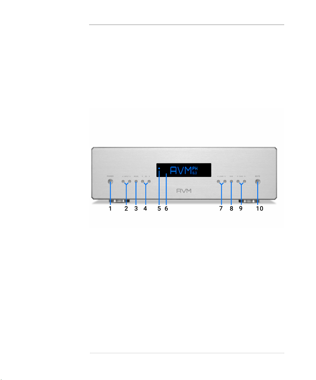
Now switch on the unit with the mains switch (18). The di s-
play (6) shows the number of the new fi rmware versi on at the
bottom lef t, the number of the existing version is shown on
the rig ht. To update, press the POWER butt on (1), i f you want
to cancel the update , press the MUTE button (1 0).

OVATION PH 8.3 7
Ge tt i ng s t a r t ed
The update takes about one minu te. After successful com ple-
tion you will b e aske d to switch of f the mains voltage (mains
switch 18) and remove the EEPROM Dongle . Th e device can
now b e switched on again and is ready for operati on.
ℹ CAUTION
Do n ot switch o ff the PH8.3 dur ing t he update pro cess. This
may l ead to un stab le operat ing con ditio ns .
If the update process was interru pted, due to a power failure
for exampl e, please proce ed as follows: Leave the EEP ROM
dongle inser ted. Switch of f th e main s voltage with the mains
switch (1 8) on the rear panel for ab ou t 10 seconds and then
switch i t on again. The software is now installed a second
time. Duri ng thi s proce ss (about one minute) the dis play (6)
remains dar k and th e standby L ED (5) flashes. Whe n the pro-
cess is complete, you will be asked to switch off the mains
voltag e (mains switch 18) an d remove the EEPROM Dongle .
The unit can the n be s witche d on again and i s re ady f or op era-
tion.
1.6 Installation and cooling
The unit may become hot depe nding on demande d output
power or en vironmental temperature. Therefore, it is impor t-
ant, that the cooli ng air can fl ow unhindered into the air in let
in the b ottom and flow out through the holes i n the rear panel.
The cooling openings in the base and re ar ensure sufficient
heat dissip ation when the un it is freely p ositioned . Th e PH 8.3
may be easily installed in a rack as long as the shelf ab ove
the unit is at least 5 cm away from the cover of t he device. If

Ge tt i ng s t a r t ed
8 OVATION PH 8.3
the unit is placed in a cabinet, p lease m ake sure t he ai r
around the uni t can circulate freely. We also recommend you
choose a l ocation that is protected f rom direct sunlig ht s o
you can read the dis play easily and th e effect of the remote
control is not impaired by extremel y bri ght sunlig ht or direct
illumination with strong hal ogen lamps . Nor t l east, th e PH 8.3
should n either be pla ced in the direct vicinity of a heating
system nor i n a par ticul arly damp environment.
1.7 Connection to mains
Connect the supplied p ower cord to the mains conne ctor (27)
and a wall outlet.
ℹ NOTE
Keep the un it swi tched off until all audi o conn ections are
mad e. I f the un it is st ill cold after un pa ckin g or fro m trans-
port, le ave i t in your listening room for about one hour with-
out mains power so that it can adju st to the room
temperature.
1.8 Mains phase indicator
Phono amplifie rs are by natu re very sen si tive to mains hum.
Therefore, i t is very important to connect the mains phase
correctly. T he PH 8.3 is equi pped with a P hase Indicator L ED
(15) on the rear panel for th is purpose.
To p erform a phase che ck , switch on th e unit with the POWER
button (1) and take a look at the Phase Indicator LED (15).

OVATION PH 8.3 9
Ge tt i ng s t a r t ed
The P hase In dicator LED only l ights up if the mains connector
is incorrectly connected and remains dark if the polarity is
correct. Phase Indication fun ctionality has deli berately been
desig ned in this way, as the control electronics of the phase
LED (1 5) produces slight interf erence when the LED is swit-
che d on. This is not the case when the mains pol arity is cor-
rect (and the LED is switched of f).
1.9 Connection of a turntable
The PH 8.3 offer s connections of up to four tur ntables with
MM or MC cartridge systems via option ally availab le input
cards (slot-in modules). To find out whether your pick-up s ys-
tem works accordin g to the M M or MC principle , please refe r
to the corresponding documentation of your pick-up syste m.
Dep ending on the design princip le of the cartridge system
used, select a suitable PH 8.3 in put board with an unbalanced
RCA inp ut or balanced XL R input of the inpu t b oard. Now con-
nect the turntable to the sockets of the input card using an
appropr iate RCA or X LR cab le. C onnect the ground cabl e
coming from the re cord pl ayer to the g rou nd contact (knur led
nut below the inp ut connectors) of the corresp onding inp ut
card.
1.10 Connection to a (pre)amplifier
Connect the outputs of the PH 8. 3 (11 , 12) to an analog high
level input of your (pre)amplifi er using s uitab le cabl es. Make
sure t he XLR connection has the correct pin ass ignme nt (see
Figure 1.3.1 , “Pi n Assig nments,” on page 4) which is also
printed on the rear panel of the device.

Ge tt i ng s t a r t ed
10 OVATION PH 8.3
ℹ CAUTION
Do n ot u se any exis ting ph ono i nputs on you r (pre)am plifier.
This would lead to input d istor tion and clip pin g.
1.11 AVM turntable supply
The PH 8.3 p rov ides a per fectly condi ti oned power supp ly for
joi nt operation wi th an AVM turntable of the ROTATION
seri es. This special power su pply whi ch is both complete ly
inde penden t from the rest of the power suppl y unit of the PH
8.3 and has an elaborately fil tered output, replaces the stan-
dard power supply unit sup plied wit h your AVM tur ntable. In
this case, us e the supply socket for AVM turntables (1 5) on
the rear p anel. You r spe cialis t dealer wi ll be pleased to supply
you w ith an appropriate cabl e.
1.11.1 External infrared input
If you have installed your PH 8.3 in su ch a way that the sup-
plie d RC 3 PHONO infrared remote control has no visual con-
tact wi th the devi ce, please connect an external receiver to
the input for an external infrared se nsor IR EXT (16).

OVATION PH 8.3 11
B as ic o pe r at io n
2. Basic operation
2.1 First operation / self test
When the unit is switched on via the mains swi tch (18), a so-
call ed self-te st is performed. The device che ck s the con figu-
ration and fu nctionality of the installed components. The cur-
rent status of the hardware test is shown on the displ ay (6 ).
Upon success ful comple ti on of the hardw are te st, the devi ce
switch es to standby mode. This process may take a few
seconds.
2.2 Switching on / standby
Usin g the pow er button (1) you can s witch betw een on (ope-
rate) an d standby. When s witche d on, the display (6) li ghts up
and the LED (3) is switched off. In standby mode the display
is switched off and the LED is on to indicate that the unit is
still connected to mains.

B as ic o pe r at io n
12 OVATION PH 8.3
Tube w ar mup
Due to the warm-up phas e of t he in te grat ed tube stage, th e
switch -on process takes ab out 30 add itional seconds . P lease
wait un til the entire re ading on the display waiting for tu be
warmu p change s comp letel y f rom lowe r to uppe r case. The
devi ce is now ready for use.
ℹ NOTE
In stand by mo de, th e device is not complet el y di sconn ected
from t he mains. To dis connect comp lete ly, u se the mains
switch (18) on the back o f th e un it or un pl ug the power cord
from t he main s conne ctor (19).
2.3 Input selection
Select the desire d in put card with the INPUT selection keys
(2). The currentl y s elected input card i s indicated on the di s-
play (6).
2.4 Adjustment of the cartridge system
For optim al sound reproduction, the ad justment of the se lec-
ted cart ridge system is of great importance. The PH 8.3
offers a wi de rang e of adjustme nt options for this purpose .

OVATION PH 8.3 13
B as ic o pe r at io n
2.4.1 Selection of a suitabl e input card
Use an MM or MC input card depend ing on the instal led car-
tri dg e syste m. Ple ase refer to the relevant documentation of
your pick- up system , to find out whether your pick-up system
works accordi ng to th e MM or MC principle.
There are two types of inputs for MC systems: The most com-
mon RCA conn ector or the balanced XLR con nector found on
some turntable s. Both types of in put cards are available for
the PH 8.3.
For MM systems, only one inp ut board with an RCA connector
is avail able .
2.4.2 Setti ng the termi nating impedance/capacity
In orde r to achieve op tim um s ound quality, each cartridge
system mus t be op erated w ith the appropr iate terminating
impedance or capacity. This is particularly im portant for MM
system s, as the termi nating capaci ty generate s a hig h-fre-
quen cy res onance that extends the frequency respons e. If the
cap acity is too low, th e sound of the pick -up system may l ack
bril liance. If the capacity is too high, the resonance shifts too
far down and thus cause s strong pe ak s in the upper fre quency
range, res ultin g in harsh and unp leasant sound rep roduction.
We recommend a cons ultation of the ope rating instructions
of you r cartridge system before ad justing th e respe ctive
impedance or capaci ty on the PH 8.3. In the oprari ng instruc-
tions you will usually fi nd the optimum termination impe-
dance or capacity. Other wi se you may use a gen eral rule: For
MM systems app rox. 200 pF cap acity, for MC systems 100
Ohm termi nating impedance.

B as ic o pe r at io n
14 OVATION PH 8.3
Dep ending on the selected card typ e (M M or MC), the imp e-
dance or cap acity may be adjusted in six ste ps. The PH 8.3
stores the last set valu e for each ind ivid ual card an d recalls it
when the cor resp onding card is selected again at a later time .
You may ad just the final impedance/capaci ty (pre ferab ly
while a record is p laying) with the LOAD impe dance /capacity
keys on the un it ( 7) or vi a the RC 3 P HONO re mote con trol.
ℹ NOTE
Plea se note th at the te rmina tion ca pacity o f MM cart ridges is
incre ased by the ca pacity o f the cable by ab out 100 pF. We
reco mmend to sele ct a setti ng o n the PH 8.3 that is a bout
100 pF bel ow the manufacturer's recom mend ed capacity.
It is wor th e xperime nting to find o ut the settin g for optimu m
soun d quality. Wrong settings will not harm the car tri dge or
the PH 8.3.
2.4.3 Gain adjustment
The output voltage of car tri dges is not standard ized. There-
fore, the re are very "loud" and very "qui et" models. However,
this has nothin g to do w ith their sound quality. In order to get
the best out of each car tr idge, the g ain of the PH 8.3 can be
set indi vidually for each i nput i n 5 dB steps. It i s re com men-
ded to star t with "0dB " and in cre as e the gain un til you are
satisf ied with t he overall sound.

OVATION PH 8.3 15
B as ic o pe r at io n
ℹ NOTE
If the gain is too h igh, the inpu t may be over loa ded an d dis-
tor ted . In this case reduce the gain of the PH 8. 3 by one or
two step s.
2.5 Selection of an equalization curve
There are two basi c p roblems i n the production of records
(also cal led "pres si ng"): Since mos t of the energy is available
in the b ass range of the musi c sig nal, very large def lections
would have to be cut into the vinyl. How ever, the large groove
spacing required f or this w ou ld reduce th e playing time of the
record to only a few minutes . Conver sely, the sign als in th e
high freque ncy rang e are very weak and would be l ost i n
groove nois e wi th "linear" cutting. Therefore, the musi c sig nal
is pre-equali zed during the prod uction process: In the bass
range the leve l i s l owered, in the hig h frequency range th e
level is rais ed. Since this is a linear distor ti on that does not
produce any harm onics, this pre-e qualization process can be
compe nsated when the re cord is pl ayed b y appl yi ng an inver-
ted e qualization cur ve to the actual p ressing cur ve.
Before the so- called RI AA equalization became standard in
the mid 1950s, recording studios of ten us ed d ifferent f re-
quen cy respon se curves when cutting their records. Whe n
such records are playe d back via an RIAA equalizer, the s ound
quali ty suffer s. The PH 8 .3 theref ore offer s a selection of th e
six most common equali zation curves us ing the EQ sel ection
keys (4). Often the labels or record sle eves of older records
show the pre-equalization used at the t ime. This can be used
to set the correct equal izati on curve on the PH 8.3 .

B as ic o pe r at io n
16 OVATION PH 8.3
If the record sle eves or labe ls do not provide any information,
tri al and error may help. For newer recordings (from the 60's
onwards) the RIAA setting i s usually applied.
ℹ NOTE
Deta iled in format ion on the time con st ants / cu t-off frequen-
cies can be found fur th er down in “Specif ications” on
page 28.
2.6 Subsonic Filter
Tu rntable s ofte n emit ve ry low frequency nois e, which has
nothing to do w ith the played back mu sic signal, but is caused
by wavy records or turntables th at are sensi ti ve to footfal l
sound . To s uppress such noi ses, the PH 8.3 i s p rovi de d with a
highl y effective subsonic fi lter which suppresses al l signals
below 3 0 Hz with a steep slop e. For activation / deactivation
use the Subs onic se lection key SUB (8 ). Th e PH 8.3 stores
the su bsonic fil ter set ting f or each ind ividu al card and recalls
it whe n the corres ponding card is se lected at a later time.
2.6.1 Mute Function
To te mp orarily mute the audi o outpu t of the PH 8.3, p lease
press the MUTE button ( 10). Press ing the button agai n turns
the MU TE function of f.

OVATION PH 8.3 17
B as ic o pe r at io n
2.6.2 Special playback setting s
With the M ODE selection key (3) the PH 8.3 may be s et to
mono m ode ("MONO" sh own i n the display) or, by p ressi ng th e
button several times, to phase rotati on by 180° in STEREO
(disp lay: "stereo-") or MONO ( "mono-" ).
For playb ack of olde r mono records th e setting of the PH 8.3
to MONO can be ver y help ful, as the groove noise (p rese nt in
stereo) is suppres se d to a ce rtai n degre e. I f, in addition, a
record has be en recorded out of p hase, the PH 8.3 can easily
correct thi s: In thi s case, choos e on e of the f ol lowing s et-
tin gs: "stereo-" or "mono" .
Table of contents
Other AVM Amplifier manuals

AVM
AVM A 30.3 User manual

AVM
AVM OVATION PA8 User manual

AVM
AVM OVATION PA 8.3 User manual

AVM
AVM OVATION MA 6.3 User manual

AVM
AVM OVATION MA 6.2 User manual

AVM
AVM A 30.3 User manual

AVM
AVM evolution m3ng User manual

AVM
AVM INSPIRATION SD 2.2 User manual

AVM
AVM EVOLUTION PA3.2 User manual

AVM
AVM OVATION SA8.2 User manual