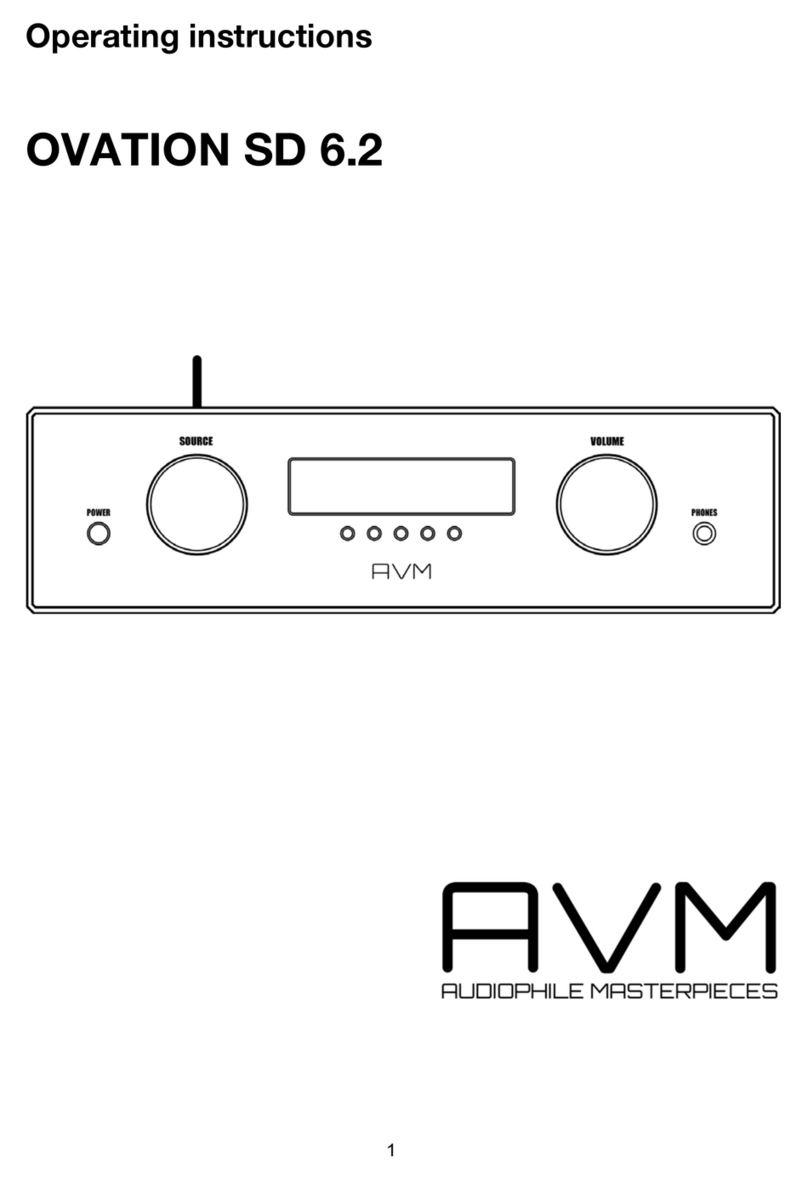
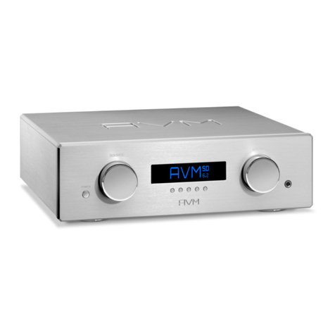
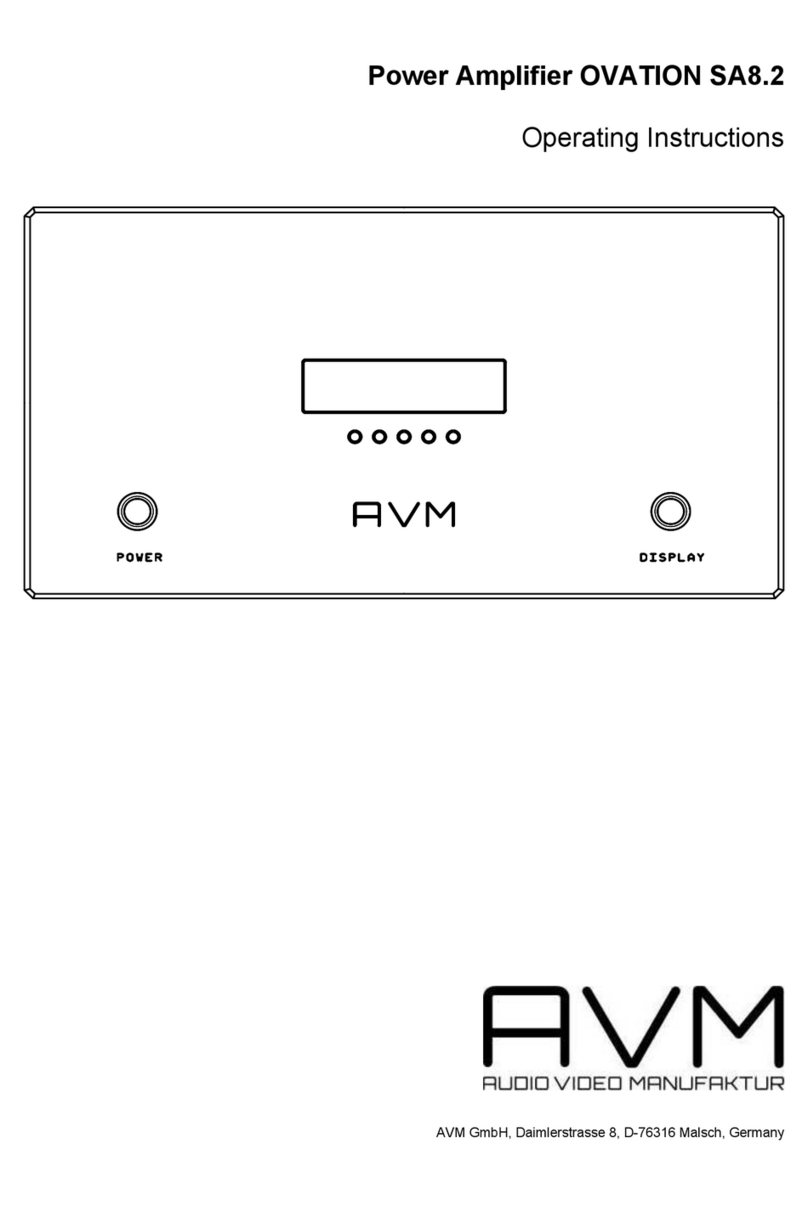
AVM OVATION MA 8.3 User manual

OVATION MA 8.3 / SA 8.3
Operating Instructions

1 Getting star ted
1.1 What‘s in the box? ... 1
1.2 Control and operating elements ... 1
1.3 Installation and cooling ... 4
1.4 Connection to mains ... 5
1.5 First start-up ... 6
1.6 Connecting trigger inputs ... 7
1.7 AIR Trigger (AVM Intelligent Remote) ... 7
1.8 Firmware update ... 8
1.9 Connecting a preamplifier ... 9
1.10 Connecting loudspeakers ... 9
2 Bas ic operation
2.1 POWER button ... 13
2.2 DISPLAY button ... 13
2.3 Operation of the menu system ... 14
2.4 Display brightness ... 14
2.5 Display modes ... 15
2.6 Operating modes ... 15
2.7 Define load impedance ... 16
2.8 Set illumination ... 16
3 Appendix
3.1 Cleaning ... 17
3.2 Troubleshooting ... 17
3.3 Conditions of warranty (EC only) ... 21

OVATION MA / SA 8.3 1
Ge tt i ng s t ar ted
1. Getting started
1.1 What‘s in the box?
• OVATION MA 8.3 (Pair) / SA 8.3
• Power cord (i n some countries)
• Trigger plu g(s) 3,5mm
1.2 Control and operating elements
The numbers in the figures below mark the control e lements.
They re fer to the numbers in the text, where the operation of
the unit is describ ed.
Fig. 1. Front panel

Ge tt i ng s t ar ted
2 OVATION MA / SA 8.3
1. Power button on/ off
2. Control LED
3. Display
4. Menu buttons (soft keys) a-e
5. Disp lay button
Fig. 2. Rear pa nel MA 8. 3
Fig. 3. Rear pa nel SA 8.3

OVATION MA / SA 8.3 3
Ge tt i ng s t ar ted
6. RC A i npu t (MA) / RC A inputs ( SA) unb alanced
7. XLR input (M A) /XLR inputs (SA) balanced
8. Mains sw itch
9. Mains ou tlet
10. Speaker terminals
11. Configu ration p or t (fi rmware upd ate s)
12. Trigger input
13. Serial por t (RS2 32)
1.2.1 Pin assignment
Fig. 4. Pin assi gnment of XLR in put(s)
1) Ground (GND)
2) Non inverting input POS (+)
3) Inverting input NEG (-)

Ge tt i ng s t ar ted
4 OVATION MA / SA 8.3
Fig. 5. Pin assi gnment of 3,5 mm trigger input (12)
1.3 Installation and cooling
The unit can be come hot d epending on the demanded output
power or en vironmental temperature. The re fore, it is impor t-
ant, that the cooling air can flow unhindered into the air i nlets
in the bottom and flow out through the holes in the rear panel.
Set up the power amplifiers so that there is at least 10 cm
distan ce arou nd the device to adjacent componen ts or w alls.
Whe n placi ng the amp lifier on a carpet, make sure that th e
feet of the unit do not sink i n ( if necessary, underl ay pucks)
and that the carpet pile d oes not seal the air slots in the floor.
Direct exposure to sunli ght is not re commended becaus e this
will heat up th e un it and may cause unw anted mal fun cti ons.
ℹ NOTE
The installed tran sformers emit magnetic stray fields . To
prevent interfere nce , it is reco mmende d to not place the
unit (s) eith er direc tly on or near a preamplifier or a record
player.
a) Ground (GND)
b) Triggervsignal (+5V to +20V)

OVATION MA / SA 8.3 5
Ge tt i ng s t ar ted
ℹ CAUTION
Heat sen si tive objects such as can dles , pl astics , records or
CD’s may also be da ma ged by th e gen erated hea t of the MA /
SA 8. 3. Great care sho uld a lso b e taken to ensure small c hil-
dre n do not bu rn themselves by accid entally touching the
amplifier( s). The hous ing does not fee l extre mely hot to
adu lts bu t small ch ild ren gen erally react more sensiti vely.
1.4 Connection to mains
Con nect the supp li ed mains cable to the powe r socket (15)
and plug it into a Schuk o socket.
ℹ NOTE
Keep the un it(s) switched off until all audio conne ctions are
made. Als o, kee p your loudspeakers disconne cte d when sw it-
ching the un it on for the first ti me. I f the device is still cold
after unpack ing from transport, place it in your liste ning
room for about one hour withou t a ma ins connecti on so t ha t
it can ad apt to t he ro om temp erature.
ℹ CAUTION: Impor tant inform ati on on ele ctrica l safety
Dep ending o n the co nnec ted loudsp eake r and the requi red
out put power, the power ampl ifiers can take u p to 3500 watts
from th e ma ins. The power co nsumpti on can be up to 16
amps. The refore, standard mains c ables (max imu m curren t

Ge tt i ng s t ar ted
6 OVATION MA / SA 8.3
10 Am père) canno t be used. The su pplied power cord is
design ed for u p to 16 a mperes. If yo u wish to replace t he
mains c able with another cable, please not e that i t is appro-
ved for at least 16 amperes and has a suitable coupling on
the device si de (IEC-60320 C19).
Con nect each out put stage to a se parate socket. Do not u se
power di str ib ution strips, as those are not designed for the
high currents req uired in total.
If the power amplifiers a re in standby mode, they a re not
completely dis con nected from the ma ins. To protect your
dev ice from d amage, unplu g the devi ce du ring a thunders-
torm o r when you are a way for a longer pe riod of ti me or
switch off t he d evice with th e mains switch (8).
1.5 First start-up
ℹ NOTE
If your power amplifi ers are still cold after unpacking due to a
previous transport, p lace them in your li stening room for at
least one hour without mains connection so t hat they can
adapt to the room temperat ure. Other wise, condensati on
could dam age or destroy th e un it.
Do not connect any loudspeakers dur ing the initial star t-up.
Turn on the power switch (8). Whil e the AVM log o ap pears i n
the display (3), the amplifier performs a self-test and s wit-
che s to standby mode aft er a few seconds . The power LED (2)
lights up.
OVATION MA / SA 8.3 7
Ge tt i ng s t ar ted
As soon as the se lf-test is completed, swi tch off the amplifier
at the mains switch (8). The device is now ready f or wiring
with other components of your sys tem.
ℹ CAUTION
Never conn ect cables to sw itched-on dev ices or disconnect
cables from s witched-on devices. Th is could damage yo ur
power amp lifier or any other conn ecte d device. Before d oing
so , turn off th e power switch or un plug the pow er cord.
1.6 Connecting trigger inputs
If you use a pre-amp lif ier that is e quipped w ith trigger out-
puts, connect them to t he trigger i nput (s) of your MA / SA 8.3
(11 ) which will automatically switch on and off together with
your pre-am plifier. The pinning of the tr igger outputs is
des cribed in section 1.6 Connecting tri gger inputs.
1.6.1 AIR Trigg er (AVM Intel lig ent Remote)
If you have connected a compati bl e AVM model such as the
OVATI ON PA 8.2 as a preampl ifier, no separate trigg er con-
nection is ne eded, since those AVM preamplifi ers send
swi tch -on/off signal s to your power amplifier i naudibly via
the connected audio cable (6, 7).

Ge tt i ng s t ar ted
8 OVATION MA / SA 8.3
1.7 Firmware update
The firmware of the MA / SA 8.3 can be updated via the confi-
gurat ion por t (11) using a special AVM update dongle. To
update your amp lifier, switch it off at the mains switch (8).
Now pl ug in the don gle as shown in the foll owing f igure and
swi tch on the device again.
Fig. 6. Firmware update wi th a special AVM don gle at the
configu ra tio n por t (11)
The disp lay (3) now show s the vers ion number of the cur-
rently installed fir mware in the left section un der current. On
the right side the ver sion number of the avai lable update is
shown und er new . With the menu buttons 4a and 4e you may
sele ct whethe r you woul d like to star t th e process (UPDATE)
or cancel it (EX IT). After the up date has been completed,
swi tch off the device at the mains switch (8) and remove the
dongle. After restarting, the device starts with the new firm-
ware .

OVATION MA / SA 8.3 9
Ge tt i ng s t ar ted
1.8 Connecting a preamplifier
The MA 8.3 provid es one RCA (6 ) and one XLR input socket
(7) each, whi ch can onl y be used alternatively. Here the pre-
amplifier is connected with a suitable cable.
The SA 8. 3 is equipped with two RCA (6) and two XLR input
sockets (7), which can also only be used al ternatively. Here
the pre amp lifier is connected wi th a suitable cable.
For longer distance s, we recommend the us e of a b alanced
XLR connection, as thi s may shield interference s more effec-
tive ly than a RCA connection.
ℹ CAUTION
Pl ease make sure th at either th e RC A or the XLR cable is
connected to the analog inputs. Otherwis e, d epe nding on the
out put impedance of the connected source d evice, simulta-
neous assign ment of the RCA (6) and X LR (7) conne ctors m ay
res ult in unfavorable s ound effects or even a short circuit .
1.9 Connecting loudspeakers
ℹ IMPORTA NT NOTES on electrical safety
The MA 8.3 i s a bri dge ou tput sta ge . This means not only t he
red (+) loudspeaker te rm inal carr ies the s ign al, b ut also t he
bla ck ( -) terminal. Never con nect one of the spe aker termi-
nals to th e cabinet or the signal ground - this may damage
your power am pli fie r or other devices o f yo ur HiFi syste m.

Ge tt i ng s t ar ted
10 OVATION MA / SA 8.3
Sin ce th e MA 8.3 delivers over 1000 watts of po wer, high vol-
tages can occur at the loudspeaker term inals. Therefore, do
not touch the terminals of either the power amplifier or t he
lou dspeaker during operation. If you want to change or
reconn ect the s pea ker cables, first switch off the power
amplifier using the ma ins switch (8).
We recomm end owners of SA 8.3 also follo w the ab ove inst-
ructions.
Make su re small ch ildren or pets do not touch the terminals
or speaker cables while the system is in op eration. To con-
nect speakers to the output jacks (10), use only good quality
spe aker cables of suffi cient cross- section . If in dou bt, ask
your dealer to recomm end the be st cab le for your speake r.
Make sure the polar ity is correct when connecting the spea-
kers. The red output term inals (10) must be connected to the
red sp eaker terminals or to the speaker terminals marked w ith
a plus sign. On the SA 8.3, the right an d left channels must
have the same pol arity of th e loudspeakers for optimum
sound reproduction.
If you are using banana plugs, turn the outer parts of the
spe aker ter minals tight (to the right) before plugging them in
so that t hey do not cause annoying rattling noises at a later
time. I f you w ant t o contact bare cable end s or cable lugs,
turn the outer par ts of the speaker terminals to the le ft as far
as th ey will go, inser t the stripped cable ends or cable lugs
from be low into the openings provid ed in the speaker termi-
nal s and then tighten the outer p ar ts of the speaker terminals
by turning them to the r igh t.
To take full advantage of the monoblock concept, we re com-
mend you place the MA 8.3 as close as pos sible to the
respective lou dspeake r. This resu lts in shor test p ossible dis-

OVATION MA / SA 8.3 11
Ge tt i ng s t ar ted
tances for the transport of the electrical powe r from the
amplifier to your loudspeaker. This installation method also
saves you long and expensive loudspeaker cab les and, last
but not leas t, makes pl ayback less sensiti ve to in terference.
If your loudspeakers react to cables that are too short with
tight b ut too thin bass, this may be due to the f act that thos e
lou dspeake rs we re design ed to operate with long cab les. Th e
cab le is therefore a 'component of the crossover ' and has an
effect on the bass rep roduction. As a result, we recomm end
you use longer cables to op erate such speakers. In case of
doubt, pleas e get i n touch with your dealer.

Ge tt i ng s t ar ted
12 OVATION MA / SA 8.3

OVATION MA / SA 8.3 13
B as ic o pe rat io n
2. Basic operation
2.1 POWER button
In perm ame nt mode the u nit i s swi tched on and of f by pre s-
sing the POWER button (1). In other operating modes (see
section 2.6 Op erating modes), the power stage is swi tche d on
and off from an external source. The POWER button is ineffec-
tive in these operating modes, which is indicated on the dis-
play wh en pres sed.
After switchi ng on, the power amplifier needs a short amount
of time to warm up the tube section. The message tube
wa rmup appears in the disp lay. Ple ase wait until th e e nti re
wa itin g for t ube warm up display changes completely from
low er case to up per case characters. The two anal og transfor-
mers for the pow er am plifiers are the n switched on and, after
che cking th at there are no errors, the protective rel ay is relea-
sed (a s equence of clicks can be heard from the device). The
MA 8.3 / SA 8.3 is now re ady for operati on.
2.2 DISPLAY button
If you wish to s witch off the dis play w hile listen ing to music,
you may deacti vate it by pressin g the DISPLAY button (5).

B as ic o pe rat io n
14 OVATION MA / SA 8.3
2.3 Menu sytem
The MA 8 .3 and SA 8.3 provide a variety of individ ual se ttings
via a key-controlled me nu system. The corresponding func-
tion of a key is shown in the display ab ove the respective key.
If no display ap pears above a key, no f unction i s assigned to
this menu i tem. The menu system works both in operat ion and
in standby mode by pressing the Menu key ( 4c) .
2.3.1 Operation of the menu system
To enter the menu , p res s the middle men u but ton (4c). Th e
display (3) now show s the fi rst menu i tem.
The current setting is hi ghl igh ted by a frame. You may chang e
the settin g b y press ing the ri ght menu buttons ( 4d, 4e). To
access other m enu items, press the left buttons (4a, 4 b). To
exi t the menu and save your settings, press the middle menu
button (4c).
If no button is pressed for more than 10 seconds, the me nu
swi tch es off automatically. Previously made sett in gs are stil l
saved.
2.4 Display brightness
Adjusts the display brightness: 100% / 75% / 50% / 25% / from
remote signal. See also se cti on 2.6 Ope rating m ode s.

OVATION MA / SA 8.3 15
B as ic o pe rat io n
2.5 Display modes
bargraph & value : During operation, a bar in di cates the cur-
rent ou tput level. A numeric display indicates the cur rent pe ak
power.
bargraph only: During op eration, a bar indicates the current
output leve l.
value only: A nume ric display shows the cu rrent peak power
output.
2.6 Operating modes
permanent (ke y POWER): The MA 8.3 / SA 8.3 is always ready
for operation as soon as it is switched on with the m ains
swi tch (8) ( standby mode).
auto : The M A 8.3 / SA 8.3 swit ches on automatically as soon
as an audio signal is detected from the preamplifier. If no si g-
nal is detected for more than ab out 6 minutes, the p owe r
amplifier switches back to standby m ode.
trigge r: The switch- on signal of a preamp lifier with sw itching
output activates the MA 8. 3 / SA 8.3 as soon as the preampli-
fier is activated. If th e p reampli fie r is switched off, the outp ut
stage als o goes into standby mode . See al so section 1.6 Con-
necting trigger inputs.
remo te: If you are using an AVM model of the PA or SD seri es,
set the operating mode to re mote. The M A / SA 8.3 switches
on automatically as soon as the correspondi ng PA or SD com-
ponent with preamp function is switched on. The s am e
applies to the switch-off process. The di gital switching sig nal

B as ic o pe rat io n
16 OVATION MA / SA 8.3
is transm itted inaudibly and without any i nfl uence on the
sound via the audio lin e (RCA or XLR). The connection of a
sep arate trigger cable is not necessary in this case. In addi-
tion, the d isplay brightness of the displ ay (4) is also adapted
to the setting of the connected PA or SD component (see sec-
tion 2. 4 Disp lay brightness ).
ℹ NOTE
If you p res s the POWER button in one of the op erating modes
auto mat ic, tr igger or remote, the d isplay shows this butt on is
without function. If you want to change this setting, press th e
menu button 4c.
2.7 Define load impedance
Here you can adju st the imped ance of the con nected spea-
kers: 2 / 4 / 8 Ohm . This setting is used exclus ivel y for cali-
brating the power display and has n o effect on the power
amplifier itself.
2.8 Set illumination
Thi s men u item allow s you to activate and deactivate add itio-
nal blue LED s in th e d evi ce as a sp ecial optical effect.

OVATION MA / SA 8.3 17
Ap p en d i x
3. Appendix
3.1 Cleaning
The surface of the housing is largely scratch-resistant and
may be cle aned wi th mild soapy wate r or a g lass cleaner and
a soft dust cloth.
ℹ CAUTION
Never allow liquid to enter the ins ide of the housin g during
cleaning. For safety rea sons, t he power cord shou ld also be
dis con nected before da mp wi ping. Do not use sol vents or
abra sives as they may damage the su rfa ce or p rin ting. The
ple xiglas panel of the cover is ve ry sensitive .
3.2 Troubleshooting
Often, supposed defects can be traced back to operating
errors. Before you contact us abou t a defect, please check th e
functions of your power amplifi er(s) accordi ng to the follo-
wing check lis t:
This manual suits for next models
1
Table of contents
Other AVM Amplifier manuals

AVM
AVM OVATION PH 8.3 User manual

AVM
AVM OVATION SA8.2 User manual

AVM
AVM OVATION A 6.2 User manual

AVM
AVM OVATION PA8 User manual

AVM
AVM evolution m3ng User manual

AVM
AVM OVATION SD 6.2 User manual

AVM
AVM OVATION MA 6.2 User manual

AVM
AVM OVATION MA 6.3 User manual

AVM
AVM INSPIRATION SD 2.2 User manual

AVM
AVM A 30.3 User manual