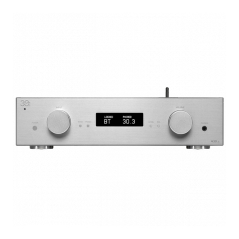
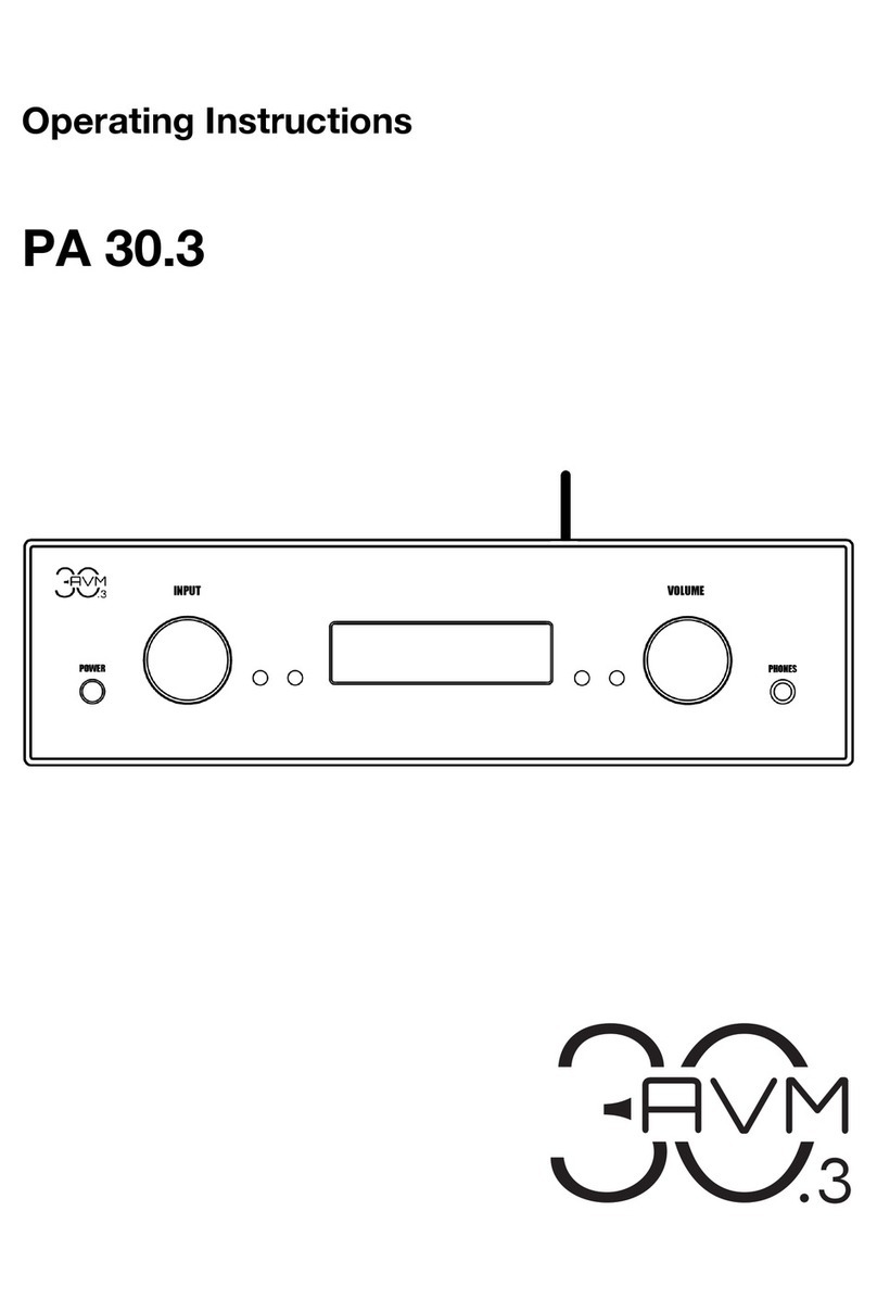
AVM A 30.3 User manual

Operating Instructions
A 30.3


Declaration of conformity (for EC only)
We herewith confirm, that the unit to which this manual belongs fulfils the EC rules necessary
to obtain the sign
the necessary measurements were taken with positive results.
AVM Audio Video Manufaktur GmbH
Daimlerstraße 8
D-76316 Malsch
Germany
www.avm.audio

Welcome!
We are pleased you have chosen an audiophile masterpiece of the AVM30 series and thank you
for your trust. With the MA 30.3 mono amplifiers you own extraordinary HiFi components with
excellent sound and a wide range of functions. In the following, we would like to explain the use
of your MA 30.3 in a comprehensive way and therefore ask you to take a little time to study this
manual in detail.
Should you have any questions which we have not been able to answer with this manual, please
contact your dealer or distributor who will be able to configure the unit according to your needs
and personal requirements and also give you instructions for daily use.
Udo Besser – AVM Owner & General Manager

Table of contents
1!Getting started.................................................................................................................... 6!
1.1!What’s in the box?........................................................................................................ 6!
1.2!Control and operating elements................................................................................... 6!
1.3!Pin assignments ........................................................................................................... 7!
1.4!Installation and cooling................................................................................................. 8!
1.5!Connection to mains .................................................................................................... 8!
1.6!Connecting a preamplifier ............................................................................................ 8!
1.7!Connection of a switching voltage ............................................................................... 8!
1.8!Connecting speakers.................................................................................................... 9!
2!Operation ............................................................................................................................ 9!
2.1!Switching device on / off .............................................................................................. 9!
2.2!Selecting the operating mode ...................................................................................... 9!
3!Appendix ........................................................................................................................... 11!
3.1!Cleaning...................................................................................................................... 11!
3.2!Troubleshooting.......................................................................................................... 11!
3.3!Conditions of warranty (EC only)................................................................................ 12!
3.4!Specifications ............................................................................................................. 13!

6
1 Getting started
1.1 What’s in the box?
• 2 x MA 30.3 mono power amplifier
• 2 x Power cord
NOTE: After unpacking, please check the scope of delivery to ensure that all parts have been
supplied and are undamaged. In case the original packing has already been opened, please
contact your local dealer. Often, your dealer prepares your new device prior to delivery to adapt
and change the configuration to your personal needs.
1.2 Control and operating elements
The numbers in the drawings below mark the control elements. They refer to the numbers in
the text, where the operation of the unit is described.

7
1 Control LED
2 Balanced input (XLR)
3 Unbalanced input (RCA)
4 TRIGGER input
5 Speaker connections
6 Operating mode selector switch
7 Diagnosis LED (OVERHEAT)
8 Diagnosis LED (OVERLOAD)
9 Power supply connection
10 Power switch
1.3 Pin assignments
1.3.1 Assignment XLR and TRIGGER inputs
XLR input TRIGGER input
1) Ground (GND) a) Ground (GND
2) Non-inverting input b) Trigger signal (+2V to +24V)
3) Inverting input
b
a

8
1.4 Installation and cooling
The MA 30.3 power amplifiers are cooled via the floor. Thus, it is very important that the air
supply from below, as well as the flow of the heated air through the slots of the lid is unhindered.
Ideally, both mono blocks are set up as freely as possible. When placing the units on a carpeted
floor, you should also make sure that the feet of the unit do not sink in (if necessary, place
pucks underneath) and that the pile of carpet does not obstruct the air flow on the floor. Also
make sure that the installation location is protected from direct sunlight.
1.5 Connection to mains
Connect the supplied power cable to the power supply connection (9) and a shockproof socket.
NOTE: Please leave the device switched off (power switch (10) in zero position) until you have
established all cable connections to the rest of the system.
1.6 Connecting a preamplifier
Your MA 30.3 are equipped with one XLR (2) and one RCA input socket (3) each, which you
can use alternatively. Here, the preamplifier is connected with a suitable cable. In case of longer
connection distances, we recommend a balanced XLR connection, since this can shield
possible interferences more effectively than an unbalanced RCA cable.
NOTE: The output impedance of your preamplifier together with the capacity of the audio cable
forms a low pass filter. When selecting the connection cables (especially for long connection
paths), you should therefore ensure that the output impedance of the preamplifier is as low as
possible and that the cable capacity is low in order not to influence the transmission of high
frequency components in the music signal. Preamplifiers from AVM such as the PA 30.3
preamplifier from the AVM30 series are always low impedance,
1.7 Connection of a switching voltage
You can connect the switching signal of your preamplifier (if available) to the TRIGGER input
(4). This allows the MA 30.3 to be conveniently switched on remotely as soon as the preamplifier
is switched on. The assignment of the control socket is described in section 1.3.
NOTE: Please note that to play back a digital signal, an appropriate source with a compatible
input signal must be present. Otherwise the message NO DIG SIGNAL will appear on the right
side of the display instead of a volume value.

9
1.8 Connecting speakers
To connect the loudspeakers to the output sockets (5) of the MA 30.3, use only loudspeaker
cables of good quality and sufficient cross-section. If in doubt, ask your dealer to recommend
the optimal cable for your speaker. When connecting the loudspeakers, also ensure that the
polarity is correct. The output socket of the MA 30.3 marked in red must be connected to the
red speaker terminal or to the speaker terminal marked with a plus sign. The right and left
channels must have the same speaker polarity. The MA 30.3 power amplifiers are each
equipped with bi-wiring connections. The two red and white output terminals are internally
connected in parallel.
NOTES: If you use banana plugs, tighten the outer parts of the sockets (clockwise) before
plugging them in, so that they cannot make disturbing rattling noises during operation. If you
want to connect bare cable ends or cable lugs, turn the outer parts of the jacks
counterclockwise as far as they will go, insert the stripped cable ends or cable lugs from below
into the openings provided in the speaker terminals and then tighten the outer parts of the jacks
by turning them clockwise.
In order to take full advantage of the sonic benefits of the mono block concept, it is
recommended to place the power amplifiers as close as possible to the controlled speaker. In
this way, you obtain short distances for the transport of electrical power from the power
amplifier to the loudspeaker.
2 Operation
2.1 Switching device on / off
The mains switch (10) is located on the back of the MA 30.3 To switch on, set it to position "1".
In position "0", the MA 30.3 is disconnected from the mains.
ATTENTION: The unit is not completely disconnected from the mains in standby mode. To
prevent damage, we therefore strongly recommend that you disconnect your MA 30.3 from the
mains supply during a thunderstorm or when you are absent for long periods of time using the
mains switch (10) located on the rear panel or by pulling out the mains plug.
2.2 Selecting the operating mode
The control LED (1) on the front panel informs you about the operating status of the MA 30.3 In
standby mode, it only lights up weakly. As soon as the MA 30.3 is in operation, the operation
indicator LED lights up in a strong blue. With the operating mode selector switch (6) on the rear,
you can select from the following operating modes:
10
2.2.1 Remote activation via a preamplifier (TRIGGER / AIR)
Remote power-on via a preamplifier with a switching output activates the MA 30.3 as soon as
you switch on the preamplifier. When the preamplifier is switched off again, the MA 30.3 goes
into standby mode as well.
If you have a recent AVM preamplifier equipped with AIR technology (AVM Intelligent
Remote), this will send a signal to the MA 30.3 when it is switched on. If the preamplifier is
switched off, it sends the switch-off signal to the MA 30.3 beforehand and the MA 30.3
automatically goes into standby mode. A separate trigger cable is not necessary for this
operating mode, since the signals are sent inaudibly over an existing AF connection.
2.2.2 Continuous operation (ON)
The MA 30.3 are always ready for operation as soon as they are switched on with the mains
switch (10).
2.2.3 Automatic switch-on via audio signal (AUTO)
In position AUTO, the MA 30.3 switches on automatically as soon as an audio signal is detected
from a connected preamplifier. If no audio signal is present for more than 5-10 minutes, the MA
30.3 returns to standby mode.
Please note that to activate a newly selected operating mode, the MA 30.3 must be switched
off for a short time of approx. 10 seconds using the mains switch (10) on the rear panel. After
you have switched on the power amplifiers again, the newly selected operating mode is
activated.

11
3 Appendix
3.1 Cleaning
Surface and pressure of the housing are largely scratch-resistant. It can be cleaned with mild
soapy water or a glass cleaner and a soft duster.
ATTENTION: Do not allow any liquid to enter the inside of the housing during cleaning. In
addition, for safety reasons, the power cord should be disconnected before damp wiping. Do
not use solvents or abrasive cleaners that could damage the surface or printing on the housing.
3.2 Troubleshooting
Often alleged defects can be traced back to operating errors. Before you contact us about a
defect, please check the functions of your mono blocks using the following checklist:
No music playback
• First check if the preamplifier and the selected signal source work correctly. The easiest
way to do this is to check the function of the preamplifier e.g. with headphones. Please do
not forget to remove the headphone plug afterwards.
• Make sure that there is no interruption (or short circuit) in the signal cable between mono
blocks and preamplifier.
• Check the connection cables between the mono block sand the connected speaker for
short circuit or interruption.
After switching off the preamplifier, the mono blocks do not automatically go to
STANDBY (after about 5 to 10 minutes), although the operating mode has been selected
to AUTO.
• Please check if after switching off the preamplifier there are soft humming or chirping noises
coming from the speakers. If this is the case, interferences in the cable interfere with the
automatic switch-on. This interprets the interference as a music signal and therefore does
not switch off the mono blocks. Lay the cable so that no interference is interfered with. With
balanced cables, an error in the pin assignment can also be the cause.
Hum during music playback
• Possibly the cable is damaged: The shield of the audio cable has a break, or the RCA plug
does not have a good ground contact (bend carefully). Use a balanced cable with wrong
assignment (the assignment of the XLR socket is described in chapter 1).

12
Device does not switch on, or switches off during operation and the blue power indicator
LED flashes
In this case one of the protection circuits has responded. The underlying error is diagnosed by
the integrated processor and indicated by the diagnosis LEDs (7, 8) on the rear panel.
• LED OVERHEAT flashes: The output stage is overheated. Switch it off with the power
switch (10) on the rear panel and wait until it has cooled down again.
• LED OVERLOAD flashes: The MA 30.3 was overloaded due to a short circuit or a defect in
the loudspeaker. Switch off the device and check if the loudspeaker cable is short circuited.
In case of bi-wiring, a short circuit can also be caused by the wrong connection of the two
loudspeaker cables.
• LED OVERHEAT and OVERLOAD are flashing simultaneously: a defect has occurred at
the power amplifier. Please contact your specialist dealer.
3.3 Conditions of warranty (EC only)
If despite expectations a defect occurs that cannot be repaired by yourself or your dealer, we
undertake the repair of your unit free of charge for up to three years from date of purchase. The
warranty covers the costs of material and working time, transport costs are to be borne by the
owner.
Provisions for this warranty are:
• The unit must have been purchased from an authorised dealer. Equipment from other
sources will not be repaired, not even at charge.
• The warranty registration card, together with a copy of the bill of sale, must be received
by us within four weeks of the date of purchase.
• The defect must not have been caused by improper handling or misuse.
• Return the unit to us only in its original packing. If this is not possible, we are entitled to
refuse acceptance. We will not assume responsibility for transport damage under any
circumstances.
• A short description of the defect is to be included with the returned unit.
• In cases of doubt we reserve the right to request a copy of the bill of sale.
• We also reserve the right to levy a handling charge for items returned without good or
valid reason, or if the unit proves to be not defective.
NOTE: If you are returning the unit from a country other than Germany you should ensure that
correct export documents are obtained. We cannot accept any charges for costs arising from
improper or incomplete export documentation.

13
If you have purchased your unit from a dealer outside Germany, please refer to him or the
relevant importing firm to process the warranty.
3.4 Specifications
Input sensitivity RCA/XLR 332 mV (25 W / 4 Ω)
Input impedance RCA 33 kΩ
Input impedance XLR 66 kΩ
Signal-to-noise ratio (25 W / 4 Ω) 97 dB(A)
THD 0.03 %
Frequency response < 5 Hz- 50 kHz
Damping factor (8 Ω) >500
Output power 136 watts (8 Ω) / 232 watts (4 Ω) / 348 (2 Ω)
Supply voltage 230 Volt / 50 Hz
Power consumption 32 W
Power consumption max. (4 Ω) 380 W
Power consumption standby 0,2 W
Dimensions (W x H x D) 230 mm x 375 mm x 132 mm
Weight 10,1 kg
Changes reserved without notice.
2020/09/23.
Other manuals for A 30.3
1
Table of contents
Other AVM Amplifier manuals

AVM
AVM EVOLUTION A3.2 User manual

AVM
AVM OVATION MA 6.2 User manual

AVM
AVM OVATION A 6.2 User manual

AVM
AVM OVATION PA8 User manual

AVM
AVM OVATION MA 8.3 User manual

AVM
AVM OVATION PH 8.3 User manual

AVM
AVM OVATION SA8.2 User manual

AVM
AVM EVOLUTION MA3.2S User manual

AVM
AVM OVATION MA 6.3 User manual

AVM
AVM OVATION A 6.3 User manual