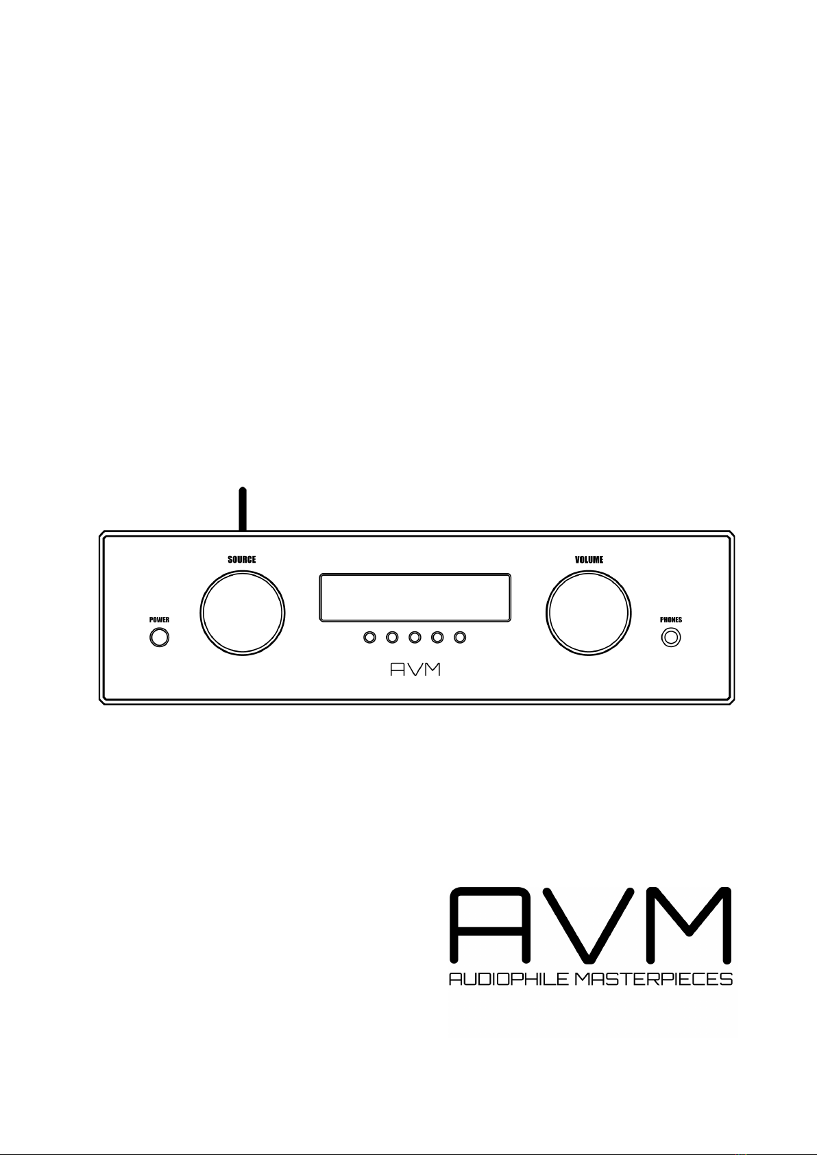
AVM OVATION SD 6.3 User manual

Operating instructions
OVATION SD 6.3
OVATION SD 8.3


Declaration of conformity (for EC only)
We herewith confirm, that the unit to which this manual belongs fulfills the EC rules necessary
to obtain the sign
the necessary measurements were taken with positive results.
AVM Audio Video Manufaktur GmbH
Daimlerstraße 8
D-76316 Malsch
Germany
www.avm.audio

A warm welcome!
We are pleased you have chosen an audiophile masterpiece from AVM and thank you for your
trust. With the OVATION SD 6.3 / 8.3 you own a high-end component with outstanding sound
quality and a wide range of functions. In the following, we would like to explain the use of your
OVATION Streaming DAC (SD) in a comprehensive way and therefore ask you to take a little time
to study this manual in detail.
Please note: Since the range of functions of your OVATION SD 6.3 / 8.3 may be expanded by
future software updates, it is in the nature of things that these instructions must also be
supplemented. The latest version of this manual is therefore always available for free download
from our website at www.avm.audio.
If you have any questions that we have not been able to answer with these instructions, please
contact your trusted dealer who will be able to configure the device according to your wishes
and personal needs and also provide you with instructions for daily use.
Udo Besser – AVM Owner & General Manager

Table of contents
1!Getting started ....................................................................................................................6!
1.1!What’s in the box? ........................................................................................................6!
1.2!Control and operating elements ...................................................................................6!
1.3!Installation and cooling .................................................................................................7!
1.4!Connection to mains .....................................................................................................7!
1.5!Connecting digital sources ...........................................................................................8!
1.6!Connecting analogue signal sources ............................................................................8!
1.7!Connecting a recorder ..................................................................................................8!
1.8!RC 9 remote control......................................................................................................8!
1.9!RC X App for iOS and Android .....................................................................................9!
1.10!Network installation (LAN, WiFi)....................................................................................9!
1.11!Software & Firmware Updates ....................................................................................18!
2!Basic operation .................................................................................................................20!
2.1!First operation / self test .............................................................................................20!
2.2!Switching on / stand by ..............................................................................................20!
2.3!Selecting a source ......................................................................................................20!
2.4!Volume setting ............................................................................................................20!
3!Advanced Settings (MENU)..............................................................................................21!
3.1!Global settings ............................................................................................................21!
3.2!Line Settings (XLR, RCA) ............................................................................................23!
3.3!Digital inputs (COAX, OPTO, USB) .............................................................................23!
3.4!Personal Setup............................................................................................................24!
3.5!Reset (Factory Settings)..............................................................................................27!
4!Appendix ............................................................................................................................28!
4.1!Cleaning ......................................................................................................................28!
4.2!Troubleshooting ..........................................................................................................28!
4.3!Conditions of warranty (EC only).................................................................................29!

6
1 Getting started
1.1 What’s in the box?
• OVATION SD 6.3 / 8.3
• WLAN antenna
• Power cable
• Optional accessory: RC 9 remote control with docking station, power supply unit,
USB charging cable
CAUTION: After unpacking, please check the scope of delivery to ensure that all parts have
been supplied and are undamaged. In case the original packing has already been opened, please
contact your local dealer. Often, your dealer prepares your new device prior to delivery to adapt
and change the configuration to your personal needs.
1.2 Control and operating elements
The numbers in the drawings below mark the control elements. They refer to the numbers in
the text, where the operation of the unit is described.
1 Power button (on / off)
2 Source Selector
3 Standby LED
4 Multifunctional buttons (a,b,c,d,e)
5 Display
6 Volume knob
7 Headphone output

7
8 Analog output left (XLR)
9 Analog output right (XLR)
10 Analog output left (Cinch, Var)
11 Analog output right (Cinch, Var)
12 Analog output left (Cinch, Fix)
13 Analog output right (Cinch, Fix)
14 Analog input right (XLR)
15 Analog input left (XLR)
16 Analog input right (Cinch)
17 Analog input left (Cinch)
18 Digital output (Optical)
19 Digital output (Coaxial)
20 Digital input USB B
21 Digital input (Optical 2)
22 Digital input (Optical 1)
23 Digital input (Coaxial 2)
24 Digital input (Coaxial 1)
25 Digital input (AES/EBU)
26 WiFi antenna socket
27 USB A input
28 Network port (LAN)
29 Status LED
30 Reset button (Streaming module)
31 Mains connector
32 Mains switch
33 Trigger outputs
34 Connector for external IR receiver
35 Phase LED
36 Link
37 Configuration port
1.3 Installation and cooling
The unit can become hot depending on demanded output power or environmental temperature.
Therefore, it is important, that the cooling air can flow unhindered into the air inlet in the bottom
and flow out through the holes in the rear panel. Direct exposure to sunlight is not
recommended because this will heat up the unit.
1.4 Connection to mains
Connect the unit to the mains outlet by using the power cord which is (in some countries)
delivered together with the unit. Make sure that mains voltage is according to the value printed
on the rear panel of the amp (near mains connector).
CAUTION: Keep the unit switched off until all audio connections are made.

8
1.4.1 Phase LED
Especially with high end audio components, which are by nature very sensitive to mains hum,
it is important to connect the mains phase correctly. The device is equipped with a Phase LED
(35) on the rear panel for this purpose.
To check the phase, switch on the unit with the power button (1) and have a look at the Phase
LED (35). This LED only lights up if the mains plug is connected with the correct polarity and
remains dark if the polarity is correct. The display has been deliberately designed in this way,
as the control electronics of the Phase LED (35) produces slight interference when the LED is
lit. This is not the case with correct mains polarity (and a dark LED).
1.5 Connecting digital sources
Connect the outputs of your digital sources to the corresponding digital inputs of the SD 6.3 /
8.3 (20 - 25). You con choose from two optical inputs (21, 22), two coaxial inputs (23, 24), the
USB B input (20), or the AES/EBU input (25).
1.6 Connecting analogue signal sources
Connect the outputs of your signal sources to the analogue inputs (14-17). The upper row is
for the left channel, the lower row is for the right channel.
1.7 Connecting a recorder
The input of a digital recorder must be connected to the digital outputs (18, 19). The signal on
the digital outputs depends on the selected source such as DIG COAX, DIG OPT.
1.8 RC 9 remote control
The optionally available RC 9 remote control allows for easy and comprehensive control of your
devices. Before you can use the RC 9 together with your device, both components need to be
connected. This process is also referred to as Pairing. In order to start the pairing process,
please follow the instructions as described in section 1.8.1. A detailed description of the entire
functionality of the optionally available RC 9 remote control can be found in a separate manual
on our AVM website at www.avm.audio.
1.8.1 Pairing
In order to control your device with a RC 9 remote control, both components need to be linked
first. This process is also referred to as Pairing. To start the pairing process, please switch off
your device by using the mains switch on the rear side of the unit. Now please navigate to the

9
Systems Settings menu on your RC 9 remote control by pressing the Settings key and
navigate to the menu item Start Pairing without selecting it with the Enter key yet. Switch on
your device by using the mains switch (30) on the rear side of the unit and immediately press
the Enter key of your RC 9 remote control to now start the Pairing process. The name of a
succesfully detected device will instantaneously be shown on the display of your RC 9 remote
control and can be edited by using the alphanumeric input keys of the RC 9 remote control.
After confirming the name of the paired device with the Enter key, you can also choose one of
four available Hotkeys. Details on how to use the Hotkey function of your RC 9 remote control
can be found in a separate manual on our website at www.avm.audio. By pressing the Enter
key on your RC 9 remote control again, the pairing process is completed.
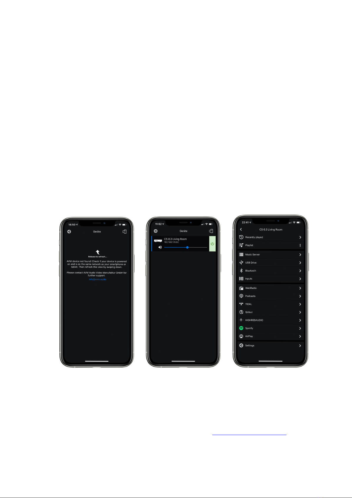
1.9 RC X App for iOS and Android
The RC X App for iOS and Android will turn your smartphone or tablet into an easy-to-use
remote control and provides a variety of intuitive features to get the most out of your network-
enabled AVM device with integrated AVM X-STREAM Engine®. The RC X App is available free
of charge and can be downloaded from the Apple App Store and the Google Play Store.
1.10 Network installation (LAN, WiFi)
To use the extensive streaming and networking features such as Spotify Connect®, Apple
AirPlay, TIDAL, QOBUZ, HIGHRESAUDIO, web radio, podcasts or music servers, your
device must be connected to your home network or the internet via a router. You can choose
from a wired LAN connection (28) or a wireless WiFi connection. When screwing the supplied
WLAN antenna onto the corresponding WLAN antenna connector (26), please make sure that
the antenna is aligned straight. Only then angle the antenna into the desired position.
LAN vs. WiFi
If you have the choice between a wired LAN or wireless WLAN connection, we generally
recommend that you use a wired LAN connection, which usually provides higher bandwidth
and is also less susceptible to interference and less dependent on the data traffic of your entire
network.
NOTE: All AVM devices with integrated AVM X-STREAM Engine® generally prefer a wired
network connection and will automatically access it once a LAN/network cable is installed on
the device (25). To still ensure smooth continuous operation via WLAN/WiFi, please remove
any LAN/network cables from the LAN/network connection (28). Otherwise, the device will re-
establish a wired network connection via LAN even during operation.
Please make sure to carefully follow all steps below to successfully set up a wired LAN
connection or a wireless WiFi connection.

10
1.10.1 Setting up a wired LAN connection
All AVM devices with integrated AVM X-STREAM Engine® are hot-pluggable. This means
that setting up a wired network connection does not require the AVM device to be restarted or
turned off and on again. Instead, a network cable (LAN cable) can be connected while the
device is running and a network connection is established immediately.
ü Plug a LAN cable from your local router or network switch into the LAN port of the device
(28).
ü The device automatically connects to your home network via the connected LAN cable
and is ready for use.
ü Make sure your smartphone or tablet is connected to your local network and start the
RC X App. After a short startup process, the RC X Appautomatically searches for
available AVM devices in your local network and lists them with their device names and IP
addresses. You can recognize an IP address by a sequence of numbers separated by
several dots. Often an IP address starts with "192.168.xxx.x".
ü Select an available device from the list by tapping it and wait a short moment until a
connection between your smartphone or tablet and the device is established.
NOTE: If you do not see any available devices, check if the network cable is installed correctly
and is on the same network as your smartphone or tablet. Then drag the view in the RC X App
slightly down to search for available devices again. Please also note the
RC X App is only compatible with AVM devices with integrated AVM X-STREAM Engine®.
You can find an overview over supported AVM devices at: www.avm.audio/rc-x-app.

11
ü To check on the network status, start the RC X App and select the AVM device.
ü Call up the menu item Network infoin Settings. In the Wireless section, you can check
on the WLAN configuration that has been established.
1.10.2 Setting up a wireless WiFi connection
To set up a wireless network connection (WLAN/WiFi) you have several options:
ü WPS
ü AirPlay configuration for iOS
ü RC X App for Android via WiFi Access Point
ü RC 9 remote control
1.10.2.1 Setup via WPS
WPS (Wi-Fi Protected Setup) is a standard for easy and secure wireless network connection
with encryption. All you need is a WiFi router with WPS function. Please refer to the relevant
documentation to find out whether your router is equipped with WPS. The setup of a WPS
connection is done via the Personal Setup Menu of your AVM device. For details on the
complete range of functions of the Personal Setup menu, please refer to section 3.4 Personal
Setup.
ü To call up the Personal Setup Menu, switch off the device completely using the mains
switch on the rear panel (32).

12
ü Now press and hold the menu button on the right below the display and switch on the
device again with the mains switch (32). As soon as the display first shows Entering setup
and then *** personal setup ***, the menu button can be released. In the Personal Setup
menu, individual menu items can be selected with the menu buttons < ITEM> and activated
accordingly with the menu button SELECT.
ü Now select the menu item set WLAN via WPS by pressing one of the menu buttons <
ITEM>.
ü Activate the WPS function by pressing the SELECT menu button. The display shows WPS
in progress.
ü Now activate the WPS function on your WiFi router within two minutes.
ü As soon as your AVM device has successfully established a WLAN connection via WPS,
the name of the connected WLAN is shown on the display, e.g.: Joined WLAN: WLAN
Name (SSID).
ü To finish the process, press the BACK menu button and then exit the Personal Setup menu
by pressing the EXIT menu button. After a short save procedure (the display shows Exit &
Save Settings) the device restarts and switches to normal operating mode.
ü Your AVM device is now connected to your local wireless network (WLAN/WiFi) and ready
for operation.
ü To check on the network status, start the RC X App and select the AVM device. Call up the
menu item Network info in Settings. In the Wireless section, you can check on the WLAN
configuration that has been established.

13
1.10.2.2 Setup via AirPlay configuration for iOS
ü First switch off the AVM device completely using the mains switch on the rear panel (32)
and wait a short moment until you switch it on again using the mains switch.
ü As soon as your AVM device has completed the startup process and is in the general
operating state, open the WLAN menu in the Settings of your iPhone or iPad. Make sure
the WLAN function is enabled and your iPhone or iPad is connected to the desired WLAN.
ü Select the AVM device you want to connect to your WLAN in the WLAN menu under the
menu item SET UP NEW AIRPLAY SPEAKER. In the example below, the AVM device is
listed as CS 6.3-00c440. Wait a moment if the device is not immediately displayed. Your
iPhone or iPad will continuously search for new devices and update the view of available
WLAN networks at short intervals. If the AVM device does not appear even after a short
wait, repeat the AVM device power-up procedure as described above.
ü In the following Airplay Setup menu, check that the desired WLAN is selected under
NETWORK and, if necessary, change the device name for your AVM device under Speaker
Name. Optionally set a password. Then start the connection process via Next. The WLAN
access data including the password is now automatically transferred from your iPhone or
iPad to your AVM device. As soon as the configuration is finished, you will receive a
corresponding feedback, which you confirm with Done. Your AVM device is now integrated
into your WLAN and ready for operation.

14
ü To check on the network status, download the RC X App for iOS from the Apple App Store
and install it on your iPhone or iPad. Then start the RC X App and select the AVM device
from the start menu.
ü Call up the menu item Network Info in the Settings. In the Wireless section, you can view
details of the WLAN configuration that has been carried out.

15
1.10.2.3 Setup via RC X App for Android & iOS via WiFi Access Point
ü Download the RC X App from the Google Play Store or Apple App Store and install it on
your smartphone or tablet.
ü Switch off the AVM device completely using the mains switch on the rear panel (32) and
wait a short moment until you switch it on again using the mains switch.
ü Once your AVM device has completed the startup process and is in general operating
mode, go to the Wireless & Networks menu in the Settings of your Android smartphone
or tablet and navigate to the WLAN menu item. Make sure that the WLAN function is turned
on and select the open WLAN network, which consists of the name softap and an attached
sequence of numbers and digits. In the example below softap_501E2D00C440.
ü If necessary, ignore the note that the selected WLAN network cannot access the Internet.
By selecting the WLAN network softap ... you create a temporary ad-hoc network, i.e., a
direct wireless connection between your Android device and the AVM device.
ü Start the RC X App and select the AVM device from the start menu.
ü Call up the menu item Network assistant in the Settings and select WLAN connection.

16
ü Use Scan to search for available wireless networks and select the wireless network you
want to use as soon as it appears in the search results. In the example below, the WLAN
network is named FRITZ!Box. A WLAN network name is also called SSID.
ü Enter the password for the WLAN network and complete the setup via Connect.
ü Call up the menu item Network Info in the Settings. In the Wireless section, you can view
details of the WLAN configuration that has been carried out.

17
1.10.2.4 Setup via optional RC 9 remote control
Before you can set up a wireless WLAN connection via the RC 9, both components must first
be connected to each other. This one-time procedure is called Pairing and is described in
section 1.8.1. A detailed description of the entire functionality of the RC 9 remote control can
be found in a separate operating manual at www.avm.audio.
ü First, perform the Pairing procedure as described in section 1.8.1 and select the newly set
up AVM device on the RC 9 using the Device Selection menu item. You can reach this
menu item via the System Settings menu that you call up by pressing the Settings button
(tool symbol) of the RC 9.
ü On the RC 9, select the menu item Settings (Einstellungen) in the main menu by pressing
the upper or lower navigation button several times.
ü By pressing the Enter button, select the menu item Network assistant and WLAN
connection.
ü By selecting the Scan menu item afterwards, your AVM device searches for available WLAN
networks and lists them in an overview.
ü Select the desired WLAN network and enter the network key (WLAN password) via the input
keys of the RC 9 after pressing Key.
ü Confirm the entered network key (WLAN password) by pressing the Enter button and select
Connect.
ü In the following overview Network Info, the Wireless section displays details of the WLAN
configuration.

18
1.11 Software & Firmware Updates
For maximum ease of use and to get the most out of your device, it is necessary to keep both
the firmware of the integrated AVM X-STREAM Engine® and the RC X App up to date. The
latest version of the RC X App can be downloaded from the Apple App Store or the Google
Play Store. To check on the installed AVM X-STREAM Engine® firmware version, use the RC
X App or the optionally available RC 9 remote control. Also, make sure your device has an
active internet connection before you perform either of the following two steps (see section
1.10).
1.11.1 AVM X-STREAM Engine® Update via the RC X App
ü Call up the menu item Firmware Update in the Settingsand select Check for Online
Update.
ü If a new version is available under SW Update or Host Update, install it by clicking Install
Update.
ü The device restarts to install the update. Do not switch off the device and wait until the
update process is completely installed. The update process will be shown on the display of
the device if necessary.
ü Once the update process is complete, the device will reboot and be ready for use again.
ü Call up the Settings of the RC X App. In the Version section, you can view details about
the currently installed firmware version.
To install a software update via a USB stick, please consult your dealer who will be happy to
assist you with the update.
1.11.2 AVM X-STREAM Engine® Update via the RC 9 remote control
ü Select the desired AVM device on the RC 9 using the menu item Device Selection. You
can reach this menu item via the System menu, which you call up by pressing the Settings
button (tool symbol) on the RC 9.
ü On the RC 9, select the menu item Settings in the main menu by pressing the upper or
lower navigation button several times.
ü Call up the menu item Firmware Update and select Check for Online Update.
ü If a new version is available under SW Update or Host Update, install it by clicking Install
Update.

19
ü The device restarts to install the update. Do not switch off the device and wait until the
update process is completely installed. The update process will be shown on the display of
the device if necessary.
ü Once the update process is complete, the device will reboot and be ready for use again.
ü Select the menu item Settings in the main menu by pressing the upper or lower navigation
key several times. In the Version section you can view details about the currently installed
firmware version.
To install a software update via a USB stick, please consult your dealer who will be happy to
assist you with the update.

20
2 Basic operation
2.1 First operation / self test
When switching on for the first time, a so-called self-test is performed if the device has been
completely disconnected from the power supply or switched off via the mains switch (32). The
device checks the configuration and functionality of the installed components. This process is
indicated by a flashing Standby LED (3) and may take a few seconds.
2.2 Switching on / stand by
With the power button (1) you can toggle between operation and standby mode. In standby
mode the display is dark and the Standby LED (3) is on. As soon as the machine is in operating
mode, the Standby LED (3) goes out and the display (5) is activated.
Tube warmup (SD 8.3)
Due to the warm-up phase of the integrated tube stage, the switch-on process of the SD 8.3
takes about 30 additional seconds. Please wait until the entire display waiting for tube warmup
changes completely from lower case to upper case. The device is now ready for operation.
CAUTION: When switched to stand by the unit is still connected to the mains. In case of a
thunderstorm or if you leave the house for a longer time, we recommend you switch the
amplifier off by using the mains switch (32) or pull the mains plug (31).
2.3 Selecting a source
A local source is selected by turning the source selector (2). You can choose between six digital
inputs and two analog stereo inputs. The selected source is shown on the left side of the display
in capital letters and is marked with SOURCE. Selecting additional sources such as Spotify
Connect®, Apple AirPlay, TIDAL, QOBUZ, HIGHRESAUDIO, Webradio, Podcasts, Music
Server or USB (STICK HDD) (24) is only possible using the optionally available RC 9remote
control or the free RC X App for iOS and Android.
NOTE: If a digital input is selected that has no valid signal, the display will show NO DIG
SIGNAL or NO USB PLUGGED instead of the volume indicator. In this state, the volume setting
is not adjustable due to the selected digital input.
2.4 Volume setting
Use the rotary encoder (6) to set the desired volume. Depending on rotating speed the volume
increases / decreases in 0.5 dB steps (slow) or 2 dB steps (fast). The actual setting is shown
on the display (5). NOTE: Please note that if the volume is changed using the optionally
available RC 9 remote control, the level always increases / decreases in 2 dB steps.
This manual suits for next models
3
Table of contents
Other AVM Media Player manuals