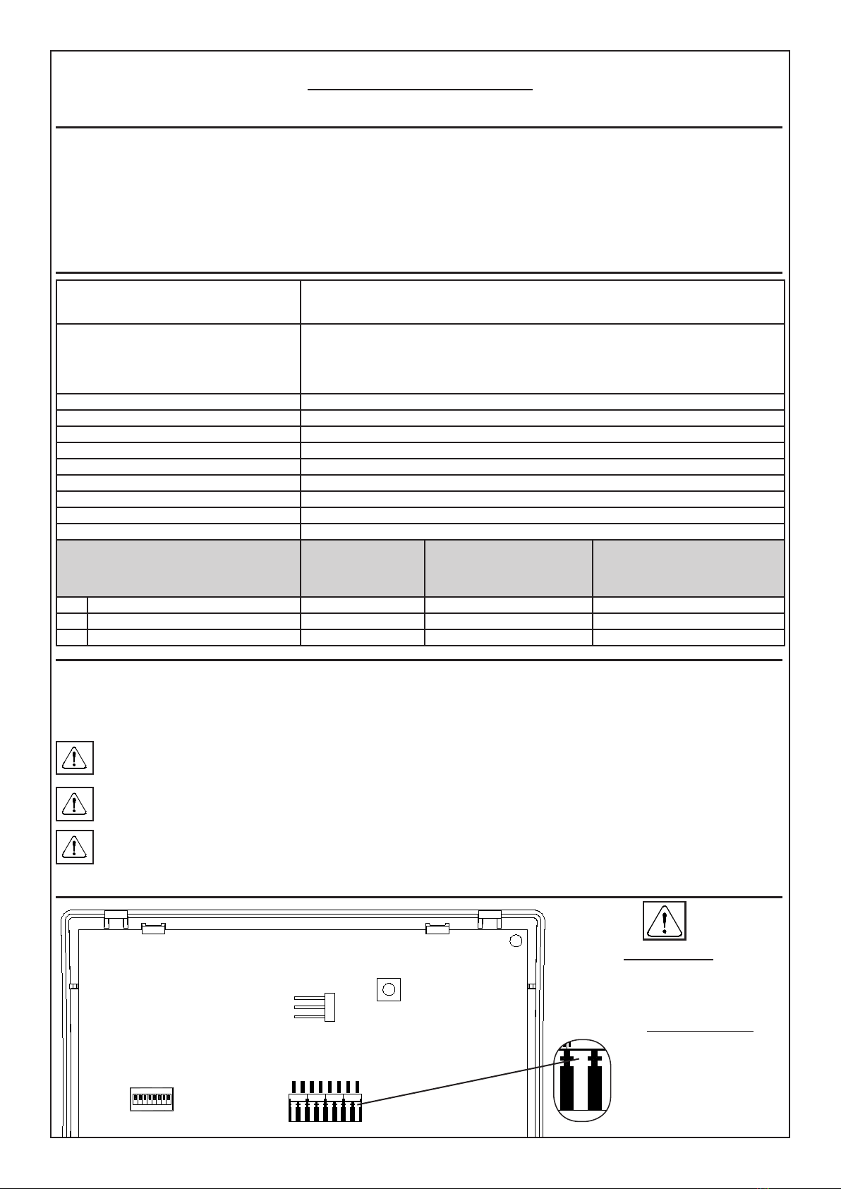
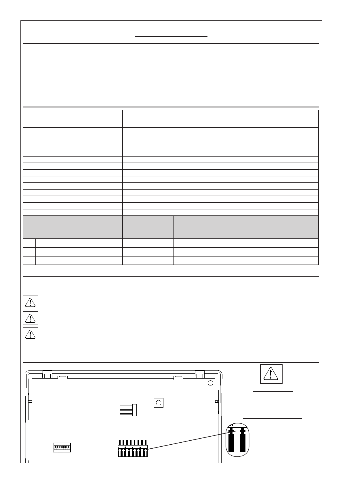
AVS Electronics XSAT WS 4 User manual

- 1 -
IST1001V1.1
Il prodotto è conforme alla direttiva CE per la compatibilità elettromagnetica.
SCHEDA SATELLITE
Via Radio
XSAT WS 4
SISTEMA DI QUALITA’
CERTIFICATO
UNI EN ISO 9001:2008
Via Valsugana, 63
35010 (Padova) ITALY
Tel. 049 9698 411 / Fax. 049 9698 407
www.avselectronics.com
assistenza tecnica 049 9698 444
I
T
A

- 2 -
ESPANSIONE XSAT WS 4
Manuale di Installazione
Generalità
• Il Ricetrasmettitore radio XSAT WS 4 permette di abbinare ad un impianto tradizionale via lo la linea dei prodotti via radio (sensori, sirene
e telecomandi) che consentono di ampliare la protezione dell’impianto
• Questa scheda è inserita in un contenitore termoplastico che ne ottimizza la resa
• Può essere posto anche a distanza dalla centrale a cui è abbinato a seconda delle esigenze installative sfruttando il collegamento seriale RS485
• Gestisce no a 32 sensori
• Gestisce no a 64 telecomandi
• Gestisce 1 sirena radio
• 2 terminali di ingresso / uscita
• Led multicolore di segnalazione
Caratteristiche generali
Linee di ingresso n° 32: congurabili con rilevazione automatica dello stato di allarme e di antimanomissione pro-
grammabile singolarmente; ogni ingresso può essere programmato in una delle possibili modalità
di funzionamento.
Terminali T1 e T2 n° 2: ingresso / uscita.
I terminali T1 e T2 possono essere programmati sia come ingresso di zona 7 e zona 8 del satellite
con singolo bilanciamento (solo allarme) o doppio bilanciamento (allarme e tamper), sia come uscite
Open Collector 7 e 8 con riferimento a negativo; oppure entrambi le programmazioni contempora-
neamente (l’ingresso di linea viene direttamente sbilanciato dall’attivazione del corrispondente O.C.)
Portata in campo aperto ~ 200 metri
Programmazione: Da tastiera con menù guidati
Collegamenti: Con quattro conduttori.
Dimensioni (L x H x P): 119 x 83 x 10 mm
Contenitore (L x H x P) 129,5 x 92 x 15,5 mm
Cond. ambientali: +5 °C / +55 °C
Tensione: nominale di alimentazione: 13,8 V =
Corrente assorbita: A riposo: 30 mA / In ricezione: 45 mA / In trasmissione: 70 mA
Grado di protezione: IPX0
Bande di frequenza usate
Occupied frequency bands
(ETSI EN 300 220-3-2 V1.1.1 (2017-02)
Wireless alarm equipment)
Massima
potenza irradiata
Maximum
radiated power
Numero di banda
Band number
According to EC Decision
2013/752/EU [i.2]
Numero di sottoclasse
della Classe 1
Class 1 sub-class number
Commision Decision 2000/299/EU [i.5]
A868,600 MHz to 868,700 MHz <10 mW e.r.p. 49 32
D869,300 MHz to 869,400 MHz <10 mW e.r.p. 53 72
E869,650 MHz to 869,700 MHz <10 mW e.r.p. 55 34
Compatibilità XSAT WS 4 con centrali AVS Electronics
Con le centrali compatibili, si possono programmare, visualizzare e monitorare continuamente tutte le funzioni relative al satellite XSAT WS 4 ed ai
sensori via radio. La centrale è in grado di riconoscere direttamente su collegamento seriale RS 485 tutti gli allarmi di zona, di tamper e tutte quelle
informazioni tecniche legate alle apparecchiature radio (antimascheramento sensori, sopravvivenza sensori, batteria bassa sensori ed interferenza
radio).
Il satellite deve essere installato ad almeno 20 cm di distanza da contenitori metallici o apparecchi elettrici che potrebbero di-
sturbarne il funzionamento.
L’alimentazione deve provenire da un circuito a bassissima tensione di sicurezza ed avente le caratteristiche di una sorgente a potenza
limitata protetta da fusibile.
INSTALLAZIONE E MANUTENZIONE DEVONO ESSERE FATTE DA PERSONALE QUALIFICATO
Scheda satellite XSAT WS 4
Inserimento cavi
Spellare il cavo per 3 - 4 mm ed inserirlo nel
morsetto corrispondente esercitando una leg-
gera pressione.
Disinserimento cavi
Esercitare una leggera pressio-
ne con un cacciavite a taglio
nel punto indicato in gura e
contemporaneamente estrarre il
cavo dalla sua sede.
ON
1 2 34 5 6 7 8
TAMPER
S1
1
1
2
3
-
T
T2
T1
-
DB
DA
+
ON
1 2 34 5 6 7 8

- 3 -
MORSETTI
+Positivo di alimentazione
DA - DB Porta per il collegamento in seriale su RS485
-Negativo di alimentazione
T1 Gestisce l’ingresso abbinato alla zona 7 e/o l’open collector abbinato all’uscita O.C. 7
T2 Gestisce l’ingresso abbinato alla zona 8 e/o l’open collector abbinato all’uscita O.C. 8
TIngresso di antimanomissione (TAMPER) bilanciato con riferimento a negativo.
-Negativo
JUMPER S1
1 - 2
2 - 3
APERTO
Pulsante TAMPER: DISABILITATO - ingresso T: DISABILITATO (LASCIARE LIBERO)
Pulsante TAMPER: ABILITATO - ingresso T: DISABILITATO (LASCIARE LIBERO)
Pulsante TAMPER: ABILITATO - ingresso T: ABILITATO
DIP SWITCH
SAT1 SAT2 SAT3 SAT4 SAT5 SAT6 SAT7 SAT8 SAT9 SAT10 SAT11 SAT12 SAT13 SAT14 SAT15 SAT16
DIP 1 Off On Off On Off On Off On Off On Off On Off On Off On
DIP 2 Off Off On On Off Off On On Off Off On On Off Off On On
DIP 3 Off Off Off Off On On On On Off Off Off Off On On On On
DIP 4 Off Off Off Off Off Off Off Off On On On On On On On On
DIP 5
DIP 6 Non usati
DIP 7 Off Disabilita la gestione degli ingressi abbinati alla zona 7 e zona 8
On Abilita la gestione degli ingressi abbinati alla zona 7 e zona 8
DIP 8 Non usato
LED MULTICOLORE
LED BIANCO Si accende quando l’antenna A è in ricezione
LED VERDE Si accende quando l’antenna B è in ricezione
LED ROSSO Si accende quando è in trasmissione
PROGRAMMAZIONE SENSORI SE ABBINATI A CENTRALI XTREAM
Parametro 1
Accelerometro attivo: impostando a “SI” si abilita la segnalazione dello strappo e del disorientamento del sensore radio come TAMPER.
Parametro 2 Basso consumo: impostando a “SI” si attiva il “Basso consumo” della batteria del sensore radio
Parametro 3 Sensibiltà Antimask: è possibile regolare la sensibilità dell’Antimask presente nel sensore impostando 4 - 100 % (Massimo) o
3- 75 % o 2- 50 %. Impostando a 1 - OFF l’Antimask risulta non attivo
Parametro 4 IR sensibilità ridotta: impostando a “SI” si attiva una riduzione della sensibilità dell’Infrarosso
Parametro 5 IR Semionda: impostando a “Doppio impulso” si attiva un’ulteriore riduzione della sensibilità dell’infrarosso
Parametro 6 Sensibilità microonda: è possibile regolare la sensibilità della Microonda presente nel sensore impostando 1 - 100 % (Mas-
simo) o 2 - 75 % o 3 - 50 % o 4 - 25 %.
Parametro 7 Abilita Morsetto IN1: nel sensore radio WIC 4 / WIC 4 Plus, impostando a “SI” si attiva il funzionamento dell’ingresso a morsetto IN1
NOTA: Nel caso di doppio canale, la congurazione di entrambi i sensori va fatta esclusivamente su quello con l’indirizzo più basso
Parametro 8 Impulsi inerziale / Switch Alarm: nel sensore radio WIC 4 / WIC 4 Plus, è possibile regolare il numero di impulsi per l’allarme
dell’ingresso IN1. 1 = Molto sensibile - 16 = Poco sensibile
Parametro 9 Abilita vibrazione: nel sensore radio WIC 4 Plus, impostando a “SI” si attiva la funzione “Vibrazione” dell’Accelerometro integrato.
Parametro 10 Sensibilità vibrazione Accelerometro: nel sensore radio WIC 4 Plus, è possibile regolare la sensibilità dell’Accelerometro
presente nel sensore. 1 = Molto sensibile - 8 = Poco sensibile
Parametro 11 Numero impulsi vibrazione: nel sensore radio WIC 4 Plus, è possibile regolare il numero degli impulsi dell’Accelerometro
presente nel sensore. 1 = Molto sensibile - 16 = Poco sensibile
PROGRAMMAZIONE SIRENA RADIO SE ABBINATA A CENTRALI XTREAM
Parametro 1
Accelerometro attivo: impostando a “SI” si abilita la segnalazione dello strappo e del disorientamento della sirena radio come TAMPER.
Parametro 2
Durata massima suono: un minuto / tre minuti
Parametro 3
Livello sonoro: è possibile selezionare tra 8 livelli sonori disponibili. 1è il Massimo e 8è il Minimo.
Parametro 4
Tono suono principale: è possibile selezionare una delle 8 tonalità a disposizione
Parametro 5
Tipo alimentazione: selezionare il tipo di alimentazione fornito alla sirena fra 1 - Batteria 6V o 2 - Alimentazione 12V +
Batteria tampone
Parametro 6
Tamper attiva sirena: impostando a “NO”, in caso di apertura del tamper/antistrappo la sirena esegue la trasmissione dell’evento
e suona in base alla programmazione della centrale abbinata
impostando a “SI”, in caso di apertura del tamper/antistrappo, la sirena esegue la trasmissione dell’evento e suona autonomamente
per il tempo impostato “Durata max. suono” o in base ai comandi inviati dalla centrale abbinata.
Parametro 7
Flash acceso/spento: abilita il ash della sirena a visualizzare con un lampeggio l’acceso/spentodella centrale; Acceso: accen-
sione continua per qualche secondo-Spento: tre lampeggi consecutivi
Parametro 8
Abilita vibrazione: (solo con “Accelerom. attivo”= SI ) impostando a “SI” si attiva la funzione “Vibrazione” dell’Accelerometro integrato.
Parametro 9 Sensibilità vibrazione Accelerometro: è possibile regolare la sensibilità dell’Accelerometro presente nella sirena. 1 = Molto sensi-
bile - 8 = Poco sensibile
.
Parametro 10
Numero impulsi vibrazione: è possibile regolare il numero degli impulsi dell’Accelerometro presente nella sirena. 1 = Molto
sensibile - 16 = Poco sensibile

- 4 -
Funzionamento
In base al tipo di centrale alla quale viene abbinato, XSAT WS 4 può gestire:
• no ad un massimo di 32 sensori radio
• no a 64 telecomandi
• n°1 sirena radio
• L’acquisizione e la programmazione dei vari accessori radio avviene tramite tastiera o software dedicato.
• Ogni impianto supporta una sola sirena radio della serie WS 4.
• Per l’attivazione e disattivazione della sirena in allarme, in centrale, deve essere programmata l’uscita relè relativa al satellite in cui è stata
memorizzata.
• Si posso attivare delle segnalazioni ottiche da parte del ash della sirena e ottiche acustiche da parte del telecomando BIP 4 Plus, program-
mando in modo adeguato le uscite O.C. 2, 3 e 4 del satellite in cui è stata memorizzata:
O.C. 2
Il ash della sirena esegue un lampeggio di “centrale accesa” quando l’o.c. si attiva e uno di “centrale spenta” quando si disattiva.
Nel BIP 4 Plus si accende il led rosso e il buzzer emette un suono lungo quando l’o.c. si attiva e si accende il led verde e il buzzer
emette due suoni brevi quando l’o.c. si disattiva
O.C. 3 Il ash della sirena esegue il lampeggio di “centrale accesa” quando l’o.c. si attiva e nessuno quando si disattiva. Nel BIP 4 Plus si
accende il led rosso e il buzzer emette un suono lungo quando l’o.c. si attiva e nulla quando l’o.c. si disattiva
O.C. 4 Il ash esegue il lampaggio di “centrale spenta” quando l’o.c. si attiva e nessuno quando si disattiva. Nel BIP 4 Plus si accende il led
verde e il buzzer emette due suoni lunghi quando l’o.c. si attiva e nulla quando l’o.c. si disattiva
• Con alcuni modelli più evoluti di centrale, anche per la programmazione della sirena radio, fare riferimento solo a quanto riportato nel ma-
nuale della centrale stessa.
Informazioni in conformità con la direttiva 1999/5/cee (r&tte)
Il prodotto oggetto della presente dichiarazione è conforme alle prescrizioni fondamentali della Direttiva 1999/5/CEE (R&TTE) sugli apparati radio-
trasmittenti di debole potenza e sull’uso delle frequenze dello spettro radioelettrico, in accordo anche con la raccomandazione CEPT 70-03.
Dichiarazione di conformità
Con la presente AVS Electronics S.p.A. dichiara che XSAT WS 4 è conforme ai requisiti essenziali e alle altre disposizioni rilevanti
stabilite dalla direttiva 2004/108/EC e conforme alla Norma Europea EN50131.
La dichiarazione di conformità può essere scaricatA al seguente link: http://www.avselectronics.com/it/software oppure uti-
lizzando il presente QRCODE
Marca AVS ELECTRONICS
Modello XSAT WS 4
Frequenza di lavoro 868 MHz
Tipo di alimentazione Corrente continua
Tensione nominale 13,8 V =
Corrente nominale 30 mA a riposo
45 mA in ricezione
70 mA in trasmissione
Paesi della comunità europea dov’è destinato ad essere utilizzato Nessuna limitazione nei Paesi UE
Data 06/07/2015
L’AVS ELECTRONICS S.p.a. si riserva il diritto di apportare modiche in qualsiasi momento e senza preavviso.

- 5 -
IST1001V1.1
The product complies with the CE directive on electromagnetic compatibility
SATELLITE
RADIO BOARD
XSAT WS 4
UNI EN ISO 9001:2008
CERTIFIED
QUALITY SYSTEM
Via Valsugana, 63
35010 (Padova) ITALY
Tel. 049 9698 411 / Fax. 049 9698 407
www.avselectronics.com
E
N
G

- 6 -
XSAT WS 4 EXPANSION
Installation Manual
General information
• The XSAT WS 4 radio transceiver combines a traditional wire system with a line of wireless radio products (sensors, sirens and remote
controls) that allow you to extend the protection of the system.
• This board is inserted in a thermoplastic container that optimizes its the performance.
• Depending on the installation needs, the XSAT WS 4 can also be placed at a distance from the controller with which it is combined using
the RS485 serial link.
• Manage up to 32 sensors
• Manage up to 64 remote controls
• Manage 1 wireless siren
• 2 terminal Input or Output
• Multi-color LED indicator
General characteristics
Input lines No 32 congurable with automatic detection of the individually programmable
alarm and anti-tamper status; each input can be programmed in one of the
possible modes of operation.
Terminal T1 and T2 n° 2: Input / Output.
The terminals T1 and T2 can be programmed as either an input zone 7 and zone 8 of the satel-
lite with one resistor (alarm only) or double resostor (alarm and tamper), both as Open Collector
outputs 7 and 8 with reference to negative; or both programs simultaneously (line input is unba-
lanced directly by activation of the corresponding OC)
Capacity in open eld ~ 200 meters
Programming: from keyboard with guided menu
Connections: Four-wire
Dimensions: (L x H x P): 119 x 83 x 10 mm
Container: (L x H x P) 129,5 x 92 x 15,5 mm
Environmental Conditions: +5 °C / +55 °C
Voltage: 13,8 V =
Current consumption: At rest: 30 mA / Receiving: 45 mA / Transmission: 70 mA
Protection grade: IPX0
Bande di frequenza usate
Occupied frequency bands
(ETSI EN 300 220-3-2 V1.1.1 (2017-02)
Wireless alarm equipment)
Massima
potenza irradiata
Maximum
radiated power
Numero di banda
Band number
According to EC Decision
2013/752/EU [i.2]
Numero di sottoclasse
della Classe 1
Class 1 sub-class number
Commision Decision 2000/299/EU [i.5]
A868,600 MHz to 868,700 MHz <10 mW e.r.p. 49 32
D869,300 MHz to 869,400 MHz <10 mW e.r.p. 53 72
E869,650 MHz to 869,700 MHz <10 mW e.r.p. 55 34
XSAT WS 4 compatibility with AVS Electronics controllers
You can program, display and continuously monitor all functions of the XSAT WS 4 satellite and the sensors via radio. Through an RS 485 serial
connection, the system directly recognizes all zone and tamper alarms and all technical information linked to the radio equipment (sensor anti-
masking, sensor survival, battery-low sensors and radio interference).
The satellite has to be installed at least 20 cm away from electrical appliances or metal containers that could disturb its operation.
The power supply must come from a very low voltage safety circuit and having the characteristics of a limited, fuse-protected power source.
INSTALLATION AND MAINTENANCE MUST BE PERFORMED BY QUALIFIED PERSONNEL
Satellite Card XSAT WS 4
ENTERING WIRES
Strip the cable for 3 - 4 mm and with soft pres-
sure insert it into the corresponding.terminal.
CABLES DISCONNECTION
With a screwdriver, press lightly
at the point indicated in the gu-
re, and pull out simultaneously
the cable from its housing.
ON
1 2 34 5 6 7 8
TAMPER
S1
1
1
2
3
-
T
T2
T1
-
DB
DA
+
ON
1 2 34 5 6 7 8

- 7 -
TERMINAL BLOCK
+Positive power
DA - DB DA / DB RS485 serial connection port
-Negative power
T1 Manages the input link to zone n° 7 and / or open collector output (OC 7)
T2 Manages the input link to zone n° 8 and / or open collector output (OC 8)
TTamper input (TAMPER) balanced with reference to negative.
-Negative
JUMPER
S1
1 - 2
2 - 3
OPEN
TAMPER Button: DISABLED - Input T: DISABLED (ALLOW FREE ENTRY T)
TAMPER Button: ENABLE - Input T: DISABLED (ALLOW FREE ENTRY T)
TAMPER Button: ENABLE - Input T: ENABLED
DIP SWITCH
SAT1 SAT2 SAT3 SAT4 SAT5 SAT6 SAT7 SAT8 SAT9 SAT10 SAT11 SAT12 SAT13 SAT14 SAT15 SAT16
DIP 1 Off On Off On Off On Off On Off On Off On Off On Off On
DIP 2 Off Off On On Off Off On On Off Off On On Off Off On On
DIP 3 Off Off Off Off On On On On Off Off Off Off On On On On
DIP 4 Off Off Off Off Off Off Off Off On On On On On On On On
DIP 5
DIP 6 Not used
DIP 7 Off Disable the input link to zone n° 7 e zone n° 8
On Enable the input link to zone n° 7 e zone n° 8
DIP 8 Not used
LED MULTICOLOR
WHITE LED It lights up when the antenna A is receiving
GREEN LED It lights up when the antenna B is receiving
RED LED It lights up when is in transmission
SENSOR PROGRAMMING IF COMBINED WITH XTREAM CONTROL PANELS
Parameter 1 Enab. accelerom.: setting to “YES” enables reporting of the strain and of disorientation of the radio sensor as TAMPER
Parameter 2 Low power mode: setting to “YES” enables the “Low consumption” of the radio sensor battery
Parameter 3 Antimask sensit.: it is possible to adjust the sensitivity of the Antimask present in the sensor by setting 4- 100% (Maximum) or
3- 75% or 2- 50% . By setting to 1- OFF the Antimask is not active
Parameter 4 IR Reduc. Sensit.: setting to “YES” enables a reduction in sensitivity of the infra-red
Parameter 5 IR Sig. integrat.: setting “Double pulse” activates a further reduction of the sensitivity of the infra-red
Parameter 6 MW Sensitivity: it is possible to adjust the microwave sensitivity present in the sensor by setting 1- 100% (max) or 2- 75% or
3- 50% or 4- 25%
Parameter 7
Enab. IN1 term.: in the radio sensor WIC 4 / WIC 4 Plus, setting to “YES” enables functioning of the terminal input IN1
NOTE: In case of double channel, conguration of both the sensors must be made exclusively on the one with the lowest
address
Parameter 8 Puls. inert/SW-AL: in the WIC 4 / WIC 4 Plus radio sensor, it is possible to adjust the number of pulses of the input alarm IN1.
1 = High sensitivity - 16 = Low sensitivity
Parameter 9 Vibration enable: in the WIC 4 / WIC 4 Plus radio sensor, setting to “YES” enables the integrated accelerometer “vibration” function.
Parameter 10 Vibration sens.: in the WIC 4 / WIC 4 Plus radio sensor, it is possible to adjust the sensitivity of the accelerometer present in
the sensor. 1 = High sensitivity - 8 = Low sensitivity
Parameter 11 Vibration pulses number: it is possible to adjust the number of pulses of the Accelerometer present in the sensor. 1 = Very
sensitive - 16 = Little sensitive
SIRENA RADIO PROGRAMMING IF COMBINED WITH XTREAM CONTROL PANELS
Parameter 1 Enab. accelerom.: setting to “YES” enables reporting of the strain and of disorientation of the radio siren as TAMPER
Parameter 2 Max time alarm: One minute/three minutes
Parameter 3 Sound level: there is a choice of 8 Levels. The values are relative to the sound level of both the Main Sound and the Alternative
Sound. 1 is the Maximum and 8 is the Minimum.
Parameter 4 Principal sound tone: it is possible to select one of 8 tones for the Principal Sound
Parameter 5 Power supply type: select the type of power supplied to the siren between 1 - Battery 6V or 2- Power supply 12V + Battery
Parameter 6
Tamper active siren: setting to “NO”, in case of tamper / antitear opening the siren transmits the event and sounds according
to the schedule of the combined central unit setting to “YES”, if the tamper / tear-off is opened, the siren transmits the event and
sounds autonomously for the time set “Max. sound “or based on commands sent from the combined control panel.
Parameter 7 Flash on / off: enables the siren ash to ash the on / off of the central ofce;
Parameter 8 Vibration enable: setting to “YES” enables the integrated accelerometer “vibration” function.
Parameter 9 Vibration sens.:it is possible to adjust the sensitivity of the accelerometer present in the siren. 1 = High sensitivity - 8 = Low
sensitivity.
Parameter 10 Vibration pulses number: it is possible to adjust the number of pulses of the Accelerometer present in the siren. 1 = Very
sensitive - 16 = Little sensitive

- 8 -
Operation
Depending on the type of controller with which it is combined, XSAT WS 4 can manage:
• up to a maximum of 32 wireless sensors
• up to 64 remote controls
• n°1 wireless siren
• The various wireless accessories are acquired and programmed through a keyboard or dedicated software.
• Each system supports only one wireless siren of the WS 4 series.
• To activate and deactivate the siren in alarm, the relay output relative to the satellite in which it is store must be programmed in the controller.
• The optical signals from the ash of the siren and the BIP 4 Plus can be activated by suitably programming the OC outputs 2, 3 and 4 of
the satellite in which it was stored:
O.C. 2
The ash of the siren does a “controller on” ash when the OC is activated and a “controller
off” ash when it is deactivated. BIP 4 Plus: when o.c. is activated the red LED lights up and the buzzer will sound and when the o.c.
is deactivated the green LED and the buzzer sounds two short beeps.
O.C. 3
The ash of the siren does a “controller on” ash when the OC is activated and none when
it is deactivated. BIP 4 Plus: when o.c. is activated the red LED lights up and the buzzer will sound and when the o.c. is deactivated
nothing happen.
O.C. 4 The ash does a “controller on” when the OC is activated and none when it is deactivated. BIP 4 Plus: when the o.c. is activated the
green LED lights up and the buzzer sounds two beeps and when the o.c. is deactivateed nothing happen.
• For programming the wireless siren of some of the more advanced controller models, refer only to what is shown in the controller manual.
Information in accordance with Directive 1999/5 / cee (r & tte)
The product covered by this declaration complies with the essential requirements of Directive 1999/5 / EC (R&TTE) on the equipment and use low
power radio transmitters frequency spectrum, in accordance with the CEPT 70-03 Recommendation.
Declaration of conformity
AVS Electronics S.p.A. declares that XSAT WS 4 complies with the essential requirements and other relevant regulations laid
down in Directive 2004/108 / EC and complies with the European Standard EN50131.
The declaration of conformity may be consulted using link: http://www.avselectronics.com/en/download-software-and-tech-
nical-manual or by using this QR CODE
Brand AVS ELECTRONICS
Model XSAT WS 4
Operating frequency 868 MHz
Type of power Direct Current
Rated voltage 13,8 V =
Rated Current 30 mA at rest
45 mA Receiving
70 mA Transmission
European Community countries where it is intended for use No restrictions in the EU countries
Date 06/07/2015
L’AVS ELECTRONICS S.p.a. reserves the right to make changes at any time without advance notice.

- 9 -
IST1001V1.1
Le présent produit est conforme à la directive CE sur la compatibilité
électromagnétique..
CARTE SATELLITE
par voie Radio
XSAT WS 4
SYSTÈME QUALITÉ
CERTIFIÉ
UNI EN ISO 9001:2008
Via Valsugana, 63
35010 (Padova) ITALY
Tel. 049 9698 411 / Fax. 049 9698 407
www.avselectronics.com
F
R
A

- 10 -
EXTENSION XSAT WS 4
Manuel d’installation
Généralités
• L’émetteur-récepteur radio XSAT WS 4 offre la possibilité de combiner à une installation traditionnelle par voie laire la ligne des produits
par voie radio (capteurs, sirènes et télécommandes) qui permettentd’augmenter la protection de l’installation.
• Cette carte est insérée dans un boîtier thermoplastique qui optimise son rendement.
• Le XSAT WS 4 peut même être placé à distance de la centrale à laquelle il est combiné en fonction des exigences de l’installation, en
utilisant la connexion sérielle RS485.
• Gère jusqu’à 32 capteurs
• Gère jusqu’à 64 télécommandes
• Gère jusqu’à 1 sirène radio
• 2 bornes d’entrée / sortie
• Indicateur LED Multi-couleur
Caratteristiche generali
Lignes d’entrée : No 32 lignes congurables avec détection automatique de l’état d’alarme et
d’anti-sabotage programmable individuellement ; chaque entrée peut être
programmée selon l’une des modalités de fonctionnement possibles.
Bornes T1 - T2 n° 2: entrée / sortie
Les bornes T1 et T2 peuvent être programmées soit comme une zone d’entrée 7 et 8 de la
zone satellite avec équilibrage individuel (alarme uniquement) ou double équilibrée (alarme et
toucher), les deux sorties de collecteurs ouverts que 7 et 8 avec référence à négative; ou les
deux programmes simultanément (entrée ligne est déséquilibrée directement par l’activation de
l’OC correspondant)
Portée en plein champ ~ 200 mètres
Programmation: à partir du clavier à l’aide de menus-guides
Connexions: Par quatre conducteurs
Dimensions (L x H x P): 119 x 83 x 10 mm
Boîtier (L x H x P) 129,5 x 92 x 15,5 mm
Conditions ambiantes: +5 °C / +55 °C
Tension: nominale d’alimentation: 13,8 V =
Courant absorbé:
Au repos: 30 mA / Pendant la réception: 45 mA / Pendant la transmission: 70 mA
Degré de protection: IPX0
Bande di frequenza usate
Occupied frequency bands
(ETSI EN 300 220-3-2 V1.1.1 (2017-02)
Wireless alarm equipment)
Massima
potenza irradiata
Maximum
radiated power
Numero di banda
Band number
According to EC Decision
2013/752/EU [i.2]
Numero di sottoclasse
della Classe 1
Class 1 sub-class number
Commision Decision 2000/299/EU [i.5]
A868,600 MHz to 868,700 MHz <10 mW e.r.p. 49 32
D869,300 MHz to 869,400 MHz <10 mW e.r.p. 53 72
E869,650 MHz to 869,700 MHz <10 mW e.r.p. 55 34
Compatibilité XSAT WS 4 avec les centrales AVS Electronics
L’on peut programmer, afcher et contrôler constamment toutes les fonctions relatives au XSAT WS 4 et aux capteurs par voie radio. La centrale
est en mesure de reconnaître directement, sur la connexion sérielle RS 485, toutes les alarmes de zone, de sabotage, ainsi que toutes les infor-
mations techniques liées aux appareils radio (anti-masquage des capteurs, survie des capteurs, faible batterie des capteurs et interférence radio).
Le satellite doit être installé à une distance d’au moins 20 cm par rapport aux boîtiers métalliques ou aux appareils électriques
susceptibles de perturber son fonctionnement.
L’alimentation doit provenir d’un circuit à très basse tension de sécurité et ayant les caractéristiques d’une source à puissance limitée
protégée par un fusible.
L’INSTALLATION ET L’ENTRETIEN DOIVENT ÊTRE EFFECTUÉES PAR UN PERSONNEL QUALIFIÉ
Carte satellite XSAT WS 4
INSERTION DES CÂBLES
Dénuder le câble sur 3 - 4 mm et l’insérer dans
le bornier correspondant en créant une légère
pression.
DÉSINSERTION DES CÂBLES
Créer une pression légère avec
un tournevis plat au point indiqué
dans le dessin et – simultaném-
ent – extraire le câble de son
siège
ON
1 2 34 5 6 7 8
TAMPER
S1
1
1
2
3
-
T
T2
T1
-
DB
DA
+
ON
1 2 34 5 6 7 8

- 11 -
BORNIER
+Positif d’Alimentation
DA - DB Connexion RS485
-Négatif d’alimentation
T1 Gère l’entrée couplée à la zone 7 et / ou de sortie de collecteur ouvert combinée OC 7
T2 Gère l’entrée couplée à la zone 8 et / ou de sortie de collecteur ouvert combinée OC 8
TTamper entrée (TAMPER) équilibré avec référence à négative.
-Négatif
JUMPER
S1
1 - 2
2 - 3
OUVERT
Bouton TAMPER: désactiver - Entrée T: désactiver (permettre l’entrée T libre)
Bouton TAMPER: Enable - Entrée T: désactiver (permettre l’entrée T libre)
Bouton TAMPER: Enable - Entrée T: activé
DIP SWITCH
SAT1 SAT2 SAT3 SAT4 SAT5 SAT6 SAT7 SAT8 SAT9 SAT10 SAT11 SAT12 SAT13 SAT14 SAT15 SAT16
DIP 1 Off On Off On Off On Off On Off On Off On Off On Off On
DIP 2 Off Off On On Off Off On On Off Off On On Off Off On On
DIP 3 Off Off Off Off On On On On Off Off Off Off On On On On
DIP 4 Off Off Off Off Off Off Off Off On On On On On On On On
DIP 5
DIP 6 Non utilisé
DIP 7 Off Disable the input link to zone n° 7 e zone n° 8
On Enable the input link to zone n° 7 e zone n° 8
DIP 8 Non utilisé
LED MULTICOLOR
LED BLANC Allume quand l'antenne A est en réception
LED VERT Allume lorsque l'antenne B est dans la réception
LED ROUGE Allume quand est dans la transmission
PROGRAMMATION DES CAPTEURS SI COMBINÉE AVEC LES PANNEAUX DE CONTRÔLE XTREAM
Parametro 1
Accéléromètre actif : oui, transmet un sabotage si le détecteur est bougé.
Parametro 2
Basse consommation : pour activer le mode basse consommation
Parametro 3
Sensibilité antimask : la sensibilité peut être réglée à 4 - 100% (maximum), 3 - 75%, 2 - 50%, 1 - OFF (pas d’antimasking)
Parametro 4
IR réduction sensibilité : pour diminuer la sensibilité IR
Parametro 5
IR sig. Integrat. : simple pulse (détection plus rapide) et double pulse (détection moins sensible).
Parametro 6
Sensibilité microonde : 1 - 100% (maximum), 2 - 75%, 3 - 50%, 4- 25% permet de réglé la distance jusqu’à laquelle le microonde va détecter.
Parametro 7
IN1 term. Actif : pour activer l’entrée auxiliaire des WIC4 et WIC4+
NOTE: Dans le cas du double canal, la conguration des deux capteurs doit être effectué exclusivement sur celui avec l’adresse la plus basse
Parametro 8
Puls inert/SW-AL : le nombre d’ouverture de l’entrée auxiliaire IN1 des contacts WIC4 qui va provoquer une alarme peut être réglé de
1=très sensible à 16=peu sensible
Parametro 9
Vibration actif : les contacts magnétiques WIC4 et WIC4+ ont également un détecteur de vibration. Ce pas de programmation permet de
l’activer.
Parametro 10
Sensibilité vibration : pour régler le détecteur de vibration desWIC4. 1=Très sensible,...,8=Peu sensible
Parametro 11
Nombre d’impulsions de vibration: dans le détecteur radio WIC 4 Plus, il est possible d’ajuster le nombre d’impulsions de l’accéléromètre
présent dans le détecteur . 1 = Très sensible - 16 = Peu sensible
PROGRAMMATION RADIO SIRENA EN COMBINAISON AVEC LES PANNEAUX DE CONTRÔLE XTREAM
Parametro 1
Accelerom.actif: si oui, transmet un sabotage si le détecteur est bougé.
Parametro 2
Durée maximum de l’alarme: une minute / trois minutes
Parametro 3
Niveau sonore : 8 niveaux sonores différents sont disponibles. Le niveau est xé pour les tonalités principales et secondaires. Le niveau
1 est le plus fort, le 8 le plus faible.
Parametro 4
Tonalité principale : Permet de choisir entre 8 sons différents pour le son de base.
Parametro 5
Type d’alimentation: sélectionnez le type d’alimentation fourni à la sirène entre 1 - 6V batteries ou 2 - Alimentation 12V + batterie de
sauvegarde
Parametro 6
Tamper attiva sirena: “NO”: en cas d’ouverture du sabotage/antiarrachage, la sirène transmet l’information et sonne selon les commandes
transmises par la centrale sur laquelle elle est installée. “OUI”: en cas d’ouverture du sabotage/antiarrachage, la sirène transmet l’informa-
tion et sonne indépendamment pour le temps réglé “Durée maximum de l’alarme” ou selon les commandes transmises par la centrale
sur laquelle elle est installée
Parametro 7
Flash Mise en/hors Service: active le ash de la sirène pour la visualisation avec un clignotement la Mise en/hors Service de la centrale.
Mise En Service : illumination continue pendant quelques secondes. Mise Hors Service : 3 clignotements consécutifs.
Parametro 8
Vibration actif: (seulement avec “Accelerom.actif”= OUI ) le réglage sur “OUI” active la fonction “Vibration” de l’accéléromètre intégré.
Parametro 9
Accéléromètre Vibration Sensibilité: Vous pouvez régler la sensibilité Accéléromètre présente dans la sirène. 1 = Très sensible - 8 =
Peu sensible
Parametro 10
Nombre Pulse Vibration: Vous pouvez régler le nombre d’impulsions Accéléromètre présentes dans la sirène. 1 = Très sensible - 16
= Peu sensible

- 12 -
Fonctionnement
En fonction du type de centrale auquel il est combiné, XSAT WS 4 peut gérer:
• jusqu’à un maximum de 32 capteurs radio
• jusqu’à 64 télécommandes
• n°1 sirène radio
• La saisie et la programmation des différents accessoires radio s’effectuent par l’entremise du clavier ou du logiciel prévu à cet effet.
• Chaque installation supporte une seule sirènes radio de la série WS 4.
• Pour activer et désactiver la sirène en alarme, dans la centrale, la sortie relais relative au satellite où celle-ci a été mémorisée doit être
programmée.
• Il est possible d’activer des signaux optiques de la part du ash de la sirène et télécommande (BIP 4 PLUS), en programmant de manière
appropriée les sorties Open Collector 2, 3 et 4 du satellite où celle-ci a été mémorisée :
O.C. 2
Le ash de la sirène émet un clignotement “centrale allumée” quand la sortie Open Collector s’active et un clignotement “centrale
éteinte” lorsqu’elle se désactive. BIP 4 Plus: quand O.C. est activé, la LED rouge allumée et le buzzer retentit et lorsque le oc est
désactivé le voyant vert et le signal sonore retentit deux bips courts
O.C. 3 Le ash de la sirène émet un clignotement “centrale allumée” quand la sortie Open Collector s’active et aucun lorsqu’elle se dés-
active. BIP 4 Plus: quand O.C. est activé, la LED rouge allumée et le buzzer retentit et lorsque le oc est désactivé rien arriver.
O.C. 4 Le ash émet un clignotement “centrale allumée” quand la sortie Open Collector s’active et aucun lorsqu’elle se désactive. BIP 4
Plus: quand O.C. est activé, la LED vert allumée et le buzzer retentit et lorsque le oc est désactivé rien arriver.
• Avec certains modèles plus évolués de centrale, pour la programmation de la sirène radio également, se référer uniquement à ce qui est
indiqué dans le manuel de la centrale.
Informations en conformité avec la Directive 1999/5/CEE (R&TTE)
Le produit faisant l’objet de la présente déclaration est conforme aux prescriptions fondamentales de la Directive 1999/ 5/CEE (R&TTE) sur les
appareils émetteurs-récepteurs de faible puissance et sur l’utilisation des fréquences du spectre radioélectrique, et ce également en accord avec
la recommandation CEPT 70-03.
Déclaration de conformité
Par la présente AVS Electronics S.p.A. déclare que XSAT WS 4 est conforme aux exigences essentielles et autres dispositions
pertinentes prévues par la directive 2004/108 / CE et est conforme à la norme européenne EN50131.
Déclaration de conformité
peut être téléchargé à l’adresse suivante
: http://www.avselectronics.com/en/download-softwa-
re-and-technical-manual
ou en utilisant ce QR Code
Marque AVS ELECTRONICS
Modèle XSAT WS 4
Fréquence de travail 868 MHz
Type d’alimentation Courant continu
Tension nominale 13,8 V =
Courant nominal 30 mA au repos
45 mA pendant la réception
70 mA pendant la transmission
Pays de la Communauté Européenne où il est destiné à être utilisé Pas de restrictions dans les pays de l’UE
Date 06/07/2015
L’AVS ELECTRONICS S.p.a. se réserve le droit d’apporter des modications à tout moment et sans préavis

- 13 -
IST1001V1.1
Das Produkt mit der CE-Richtlinie über elektromagnetische Verträglichkeit
SATELLITE RADIO BOARD
XSAT WS 4
ZERTIFIZIERTES
QUALITÄTSSYSTEM
UNI EN ISO 9001:2008
Via Valsugana, 63
35010 (Padova) ITALY
Tel. 049 9698 411 / Fax. 049 9698 407
www.avselectronics.com
D
E
U

- 14 -
XSAT WS 4 ERWEITERUNG
Installationsanleitung
ALLGEMEINE INFORMATIONEN
• Der XSAT WS 2 Funkempfänger bildet die Schnittstelle zwischen der verkabelten Zentrale und den verschiedenen Funkkomponenten
(Sensoren, Signalgeber und Fernbedienungen). Er bietet die Möglichkeit die Reichweite eines zu überwachenden Bereiches zu erhöhen.
• Das Modul ist in einem Kunststoffgehäuse verbaut, welches seine Leistung optimiert.
• Abhängig von den Anforderungen an das System, kann das XSAT WS 4 auch abgesetzt von der Zentrale montiert werden. Verbunden
werden die beiden Komponenten mittels serieller RS485 Schnittstelle.
• Verwaltung bis zu 32 Funk-Sensoren
• Verwaltung bis zu 64 Fernbedienungen
• Verwaltung 1 Funksignalgeber
• 2 Eingang oder Ausgang Anschlussklemmen
• Mehrfarbige LED-Anzeige
TECHNISCHE DATEN
Eingangslinien
32 kongurierbare, mit automatischer Detektion durch individuell programmierbaren Alarm und
Sabotage Status; jeder Eingang kann in einen der möglichen Betriebsarten programmiert werden.
Anschlüsse T1 und T2 2: Eingang / Ausgang.
Die Anschlüsse T1 und T2 können entweder als Eingänge Zone 7 und Zone 8 des Satelliten, mit
Einzelabgleich (nur Alarm) oder Doppelabgleich (Alarm und Sabotage) programmiert werden,
oder als Open-Collector-Ausgänge 7 und 8, mit Bezug auf negativ, oder beide Optionen gleich-
zeitig (Linien-Eingang ist unausgeglichen direkt durch Aktivierung des entsprechenden OCs).
Reichweite (im freien Feld) ~ 200 Meter
Programmierung mittels Bedienteil, menügeführt
Verkabelung vieradrig
Abmessungen Platine (L x B x H ) 119 x 83 x 10 mm
Abmessungen Gehäuse (L x B x H) 129,5 x 92 x 15,5 mm
Betriebstemperatur +5 °C bis 55 °C
Versorgungsspannung 13,8 V =
Stromaufnahme in Ruhe: 30 mA / in Empfang: 45 mA / in Übertragung: 70 mA
Schutzart IPX0
Bande di frequenza usate
Occupied frequency bands
(ETSI EN 300 220-3-2 V1.1.1 (2017-02)
Wireless alarm equipment)
Massima
potenza irradiata
Maximum
radiated power
Numero di banda
Band number
According to EC Decision
2013/752/EU [i.2]
Numero di sottoclasse
della Classe 1
Class 1 sub-class number
Commision Decision 2000/299/EU [i.5]
A868,600 MHz to 868,700 MHz <10 mW e.r.p. 49 32
D869,300 MHz to 869,400 MHz <10 mW e.r.p. 53 72
E869,650 MHz to 869,700 MHz <10 mW e.r.p. 55 34
XSAT WS 4 KOMPATIBILITÄT MIT AVS ELECTRONICS ZENTRALEN
Können alle Funktionen des XSAT WS 4 Satelliten und die Funksensoren programmiert, angezeigt und überwacht werden. Durch die serielle
RS485 Verbindung erkennt das System direkt alle Zonen und Sabotage Alarme und alle technischen Informationen in Verbindung mit den Funk
Komponenten (Sensor Abdecküberwachung, Sensor Verfügbarkeit, Sensor Batteriezustand und Funkstörungen).
Der Sender muss mindestens 20cm entfernt von elektrischen Geräten oder metallischen Gegenständen installiert werden um
einen störungsfreien Betrieb zu gewährleisten.
Die Spannungsversorgung muss von einer Sicherheitsniederspannungsschaltung kommen, mit den Eigenschaften einer begrenzten
Spannungsversorgung, durch eine Sicherung geschützt.
INSTALLATION UND WARTUNG MÜSSEN VON QUALIFIZIERTEM PERSONAL VORGENOMMEN WERDEN
SATELLITEN PLATINE XSAT WS 4
VERDRAHTUNG
Das Kabel ca. 3 - 4 mm abisolieren und mit
leichtem Druck in die entsprechende Klemme
bis zum Ende einfügen
KABEL ENTFERNEN
Mit einem Schraubendreher
leicht an den in der Abbildung
angegebenen Punkt drücken und
gleichzeitig das Kabel aus der
Klemme herausziehen.
ON
1 2 34 5 6 7 8
TAMPER
S1
1
1
2
3
-
T
T2
T1
-
DB
DA
+
ON
1 2 34 5 6 7 8

- 15 -
ANSCHLUSSKLEMMEN
+
Positive Spannungsversorgung
DA - DB
DA /DB RS485 serielle BUS-Anbindung
-
Negative Spannungsversorgung
T1
Verwaltet den Eingang (Einzel- oder Doppelausgleich-Widerstand), verknüpft mit Zone Nr. 7 und / oder Open Collector Ausgang (OC 7)
T2
Verwaltet den Eingang (Einzel- oder Doppelausgleich-Widerstand), verknüpft mit Zone Nr. 8 und / oder Open Collector Ausgang (OC 8)
T
Sabotageeingang (TAMPER), mit negativen Bezug
-
Negativ
JUMPER
S1
1 - 2
2 - 3
OFFEN
SABOTAGE Taster: DEAKTIVIERT:
SABOTAGE Taster: AKTIVIERT:
- Eingang T: DEAKTIVIERT (ermöglichen freien eingang T)
- Eingang T: AKTIVIERT
DIP SWITCH - Empfänger Adresse
ERW1 ERW2 ERW3 ERW4 ERW5 ERW6 ERW7 ERW8 ERW9 ERW10 ERW11 ERW12 ERW13 ERW14 ERW15 ERW16
DIP 1 Off On Off On Off On Off On Off On Off On Off On Off On
DIP 2 Off Off On On Off Off On On Off Off On On Off Off On On
DIP 3 Off Off Off Off On On On On Off Off Off Off On On On On
DIP 4 Off Off Off Off Off Off Off Off On On On On On On On On
DIP 5
DIP 6 Nicht benutzt
DIP 7 Off Deaktivieren Sie die Verwaltung der Eingänge in die Zone 7 und Zone 8 gekoppelt
On Ermöglicht die Verwaltung von Eingaben in die Zone 7 und Zone 8 gekoppelt
DIP 8 Nicht benutzt
MEHRFARBEN LED
WEISSE LED Leuchtet auf, wenn die Antenne A empfängt
GRÜNE LED Leuchtet auf, wenn die Antenne B empfängt
ROT LED Leuchtet auf, wenn überträgt
MELDER PROGRAMMIERUNG, IN VERBINDUNG MIT XTREAM ZENTRALEN
Parameter 1
Akti. Beschleunigungssensor.: Einstellung „JA” ermöglicht die Meldung des Abriss und / oder Verstellen des Funkmelders als
SABOTAGE
Parameter 2
Energiesoparmodus.: Einstellung „JA” aktiviert den „Energiesparmodus“ des Funkmelders
Parameter 3
Abdecküberw. Emp.: Ermöglicht die Empndlichkeit der Abdecküberwachung des Melders von 4 - 100% (Maximum) oder 3 -
75% oder 2 - 50% einzustellen. Bei auf 1 - AUS ist die Abdecküberwachung deaktiviert
Parameter 4
IR Empndlichkeit: Einstellung „JA” ermöglicht die Reduzierung der Infrarot-Empndlichkeit
Parameter 5
IR Signal: Die Einstellung „Doppelimpuls” aktiviert eine weitere Reduzierung der Empndlichkeit des Infrarots
Parameter 6
MW Empndlichkeit: Ermöglicht die Mikrowellen-Empndlichkeit von 1 - 100% (Maximum) oder 2 - 75% oder 3 - 50% oder 4 - 25
%einzustellen.
Parameter 7
Akti. IN 1 Eingang: Ermöglicht den Eingang IN1 der Funk-Melder WIC 4 / WIC 4 Plus durch „JA” zu aktivieren
HINWEIS: Bei Doppelkanal muss die Konguration beider Melder ausschließlich an der mit der niedrigeren Adresse vorgenommen
werden
Parameter 8
Anzahl Impulse Eingang: Ermöglicht die Anzahl der Alarmimpulse des Eingangs IN1 der Funk-Melder WIC 4 / WIC 4 Plus einzus-
tellen; 1 = Hohe Empndlichkeit – 16 = Niedrige Empndlichkeit
Parameter 9
Akti. Erschütterung: Einstellung „JA” aktiviert die „Vibrationerkennung“ im Funk-Melder WIC 4 Plus des Beschleunigungssensors
Parameter 10
Erschütterung Empf.: Ermöglicht die Empndlichkeit der Erschütterung des Funk-Melders WIC 4 Plus einzustellen; 1 = Hohe
Empndlichkeit – 8 = Niedrige Empndlichkeit
Parameter 11
Anzahl Impulse Erschütterung: Ermöglicht die Anzahl der Erschütterung des Funk-Melders WIC 4 Plus einzustellen; 1 = Hohe
Empndlichkeit – 16 = Niedrige Empndlichkeit
SIGNALGEBER PROGRAMMIERUNG, IN VERBINDUNG MIT XTREAM ZENTRALEN
Parameter 1
Akti. Beschleunigungssensor.: Einstellung „JA” ermöglicht die Meldung des Abriss und / oder Verstellen der Funk-Sirene als
SABOTAGE
Parameter 2
Max. Alarm-Zeit: 1 Minute oder 3 Minuten
Parameter 3
Lautstärke Ton: Auswahl von 8 Lautstärken. Werte in Ralation zum Klangpegel des Alarmtons; 1 = Maximum und 8 = Minimum.
Parameter 4
Tonklang: Auswahl von 8 verschiedenen Alarmtönen
Parameter 5
Spannungsversorung-Typ: Auswahl der Art der Spannungsversorung der Sirene zwischen 1 - Batterie 6V oder 2 - 12V Span-
nungsversorung + Batterie
Parameter 6
Sabotage aktiviert Sirene: Einstellung „NEIN”: bei Sabotage / Abriss / Öffnung sendet die Sirene das Ereignis und ertönt laut der
Zeitdauer der angebundenen Zentrale; Einstellung „JA”: bei Sabotage / Abriss / Öffnung sendet die Sirene das Ereignis und ertönt
autonom für die eingestellte Zeit „Max. Alarm-Zeit”oder basierend auf die Konguration der angebundenen Zentrale.
Parameter 7
Blitz scharf/unscharf: Ermöglicht die Signalisierung der Scharf- / Unscharfschaltung der Zentrale durch die Sirene
Parameter 8
Akti. Erschütterung: Einstellung „JA” aktiviert die „Vibrationerkennung“ des Beschleunigungssensors
Parameter 9
Erschütterung Empf.: Ermöglicht die Empndlichkeit der Erschütterung einzustellen; 1 = Hohe Empndlichkeit – 8 = Niedrige
Empndlichkeit
Parameter 10
Anzahl Impulse Erschütterung: Ermöglicht die Anzahl der Erschütterung einzustellen; 1 = Hohe Empndlichkeit – 16 = Niedrige
Empndlichkeit

- 16 -
BETRIEB
• In Abhängigkeit des eingesetzten Zentralentyps kann das XSAT WS 4:
• bis zu 32 Funk-Sensoren
• bis zu 64 Fernbedienungen
• 1 Funksignalgeber verwalten.
• Die verschiedenen drahtlosen Komponenten werden über das Bedienteil oder der speziellen Software erkannt und programmiert.
• Jedes System unterstützt einen Funksirenen der WS 4-Serie.
• Zur Aktivierung und Deaktivierung des Signalgebers bei Alarm, muss der entsprechende Relaisausgang des Satelliten in der Zentrale
programmiert werden.
• Die optische Signalisierung (Blitz) und der BIP 4 Plus werden durch die Programmierung der OC Ausgänge 2, 3 und 4 des jeweiligen
Satelliten aktiviert:
O.C. 2
Der Signalgeber gibt einen “Zentrale scharf”-Blitz wieder wenn OC aktiviert wird und ein “Zentrale unscharf”-Blitz bei OC Deaktivie-
rung.
BIP 4 Plus: Wenn der OC aktiviert wird leuchtet die rote LED auf und der Summer ertönt und bei OC Deaktivierung leuchtet die grüne
LED und der Summer ertönt zweimal kurz.
O.C. 3 Der Signalgeber gibt einen “Zentrale scharf”-Blitz wieder wenn OC aktiviert wird und es passiert nichts bei OC Deaktivierung.
BIP 4 Plus: Wenn der OC aktiviert wird leuchtet die rote LED auf und der Summer ertönt und bei OC Deaktivierung passiert nichts.
O.C. 4
Blitz bei “Zentrale scharf” wenn OC aktiviert wird und es passiert nichts bei Deaktivierung.
BIP 4 Plus: Wenn der OC aktiviert wird leuchtet die grüne LED auf und der Summer ertönt zweimal kurz und bei OC Deaktivierung
passiert nichts.
• Die Programmierung der Funksignalgeber in Verbindung mit weiteren Zentralen ist in dem entsprechenden Handbuch der Zentrale nach-
zulesen.
Information gemäß der Richtlinie 1999/5 / cee (r & tte)
Das hier beschriebene Produkt entspricht im Wesentlichen den Vorschriften der Richtlinie 1999/5 / CEE (R&TTE) über Funkübertragungseinrichtungen
niedriger Leistung und die Verwendung von Frequenzen des funkelektrischen Spektrums, entsprechend CEPT 70-03 Empfehlung.
KONFORMITÄTSERKLÄRUNG
AVS Electronics S.p.A. erklärt hiermit, dass der XSAT WS 4 mit den grundlegenden Anforderungen und anderen relevanten
Bestimmungen der Richtlinie 2004/108 / EC und mit der Europäischen Norm EN50131 übereinstimmt.
Die Konformitätserklärung kann unter folgendem Link eingesehen werden: http://www.avselectronics.com/en/downlo-
ad-software-and-technical-manual oder mit durch Nutzung dieses QR CODES
Hersteller AVS ELECTRONICS
Modell XSAT WS 4
Arbeitsfrequenz 868 MHz
Spannungsversorgung Direkte Versorgung
Nennspannung 13,8 V =
Stromaufnahme 30 mA (in Ruhe)
45 mA (in Empfang)
70 mA (in Übertragung)
Länder in der Europäischen Gemeinschaft in der es verwendet wird Keine Einschränkungen in EU-Ländern
Datum 06/07/2015
L’AVS ELECTRONICS S.p.a. behält sich das Recht vor, Änderungen jederzeit und ohne vorherige Ankündigung vorzunehmen
Table of contents
Languages:
Other AVS Electronics Transceiver manuals