AVS Electronics XSATWS 2 User manual

- 1 -
IST0886V2.3
Il prodotto è conforme alla direttiva CE per la compatibilità elettromagnetica.
SCHEDA SATELLITE
Via Radio
XSATWS 2
SISTEMA DI QUALITA’
CERTIFICATO
UNI EN ISO 9001:2008
Via Valsugana, 63
35010 (Padova) ITALY
Tel. 049 9698 411 / Fax. 049 9698 407
www.avselectronics.com
assistenza tecnica 049 9698 444
I
T
A

- 2 -
ESPANSIONE XSATWS 2
Manuale di Installazione
Generalità
• Il Ricetrasmettitore radio XSATWS 2 permette di abbinare ad un impianto tradizionale via lo la linea dei prodotti
via radio (sensori, sirene e telecomandi) che consentono di ampliare la protezione dell’impianto
• Questa scheda è inserita in un contenitore termoplastico che ne ottimizza la resa
• Può essere posto anche a distanza dalla centrale a cui è abbinato a seconda delle esigenze installative sfrut-
tando il collegamento seriale RS485
• Gestisce no a 32 sensori
• Gestisce no a 64 telecomandi
• Gestisce 1 sirena radio
• 2 terminali di ingresso / uscita
• Led multicolore di segnalazione
Caratteristiche generali
Linee di ingresso n° 32: congurabili con rilevazione automatica dello stato di allarme e di antimano-
missione programmabile singolarmente; ogni ingresso può essere programmato in
una delle possibili modalità di funzionamento.
Terminali T1 e T2 n° 2: ingresso / uscita.
I terminali T1 e T2 possono essere programmati sia come ingresso di zona 7 e zona
8 del satellite con singolo bilanciamento (solo allarme) o doppio bilanciamento (al-
larme e tamper), sia come uscite Open Collector 7 e 8 con riferimento a negativo;
oppure entrambi le programmazioni contemporaneamente (l’ingresso di linea viene
direttamente sbilanciato dall’attivazione del corrispondente O.C.)
Frequenza 868 MHz a singola frequenza
Portata in campo aperto ~ 150 metri
Programmazione: Da tastiera con menù guidati
Collegamenti: Con quattro conduttori.
Dimensioni (L x H x P): 119 x 83 x 10 mm
Contenitore (L x H x P) 129,5 x 92 x 15,5 mm
Cond. ambientali: +5 °C / +55 °C
Tensione: nominale di alimentazione: 13,8 V =
Corrente assorbita: A riposo: 30 mA / In ricezione: 45 mA / In trasmissione: 70 mA
Grado di protezione: IPX0
Compatibilità XSATWS 2 con centrali AVS Electronics
• Logitel8 Plus Advance (da vers.2.1)
• ADVANCE88
• Concorde Plus 54
• Xtream 640 - 64 - 32 - 6
con queste centrali, si possono programmare, visualizzare e monitorare continuamente tutte le funzioni relative al
satellite XSAT WS2 ed ai sensori via radio. La centrale è in grado di riconoscere direttamente su collegamento seriale
RS 485 tutti gli allarmi di zona, di tamper e tutte quelle informazioni tecniche legate alle apparecchiature radio (anti-
mascheramento sensori, sopravvivenza sensori, batteria bassa sensori ed interferenza radio).
Il satellite deve essere installato ad almeno 20 cm di distanza da contenitori metallici o apparecchi
elettrici che potrebbero disturbarne il funzionamento.
L’alimentazione deve provenire da un circuito a bassissima tensione di sicurezza ed avente le caratteristiche
di una sorgente a potenza limitata protetta da fusibile.
INSTALLAZIONE E MANUTENZIONE DEVONO ESSERE FATTE DA PERSONALE QUALIFICATO

- 3 -
ON
1 2 34 5 6 7 8
TAMPER
S1
1
1
2
3
-
T
T2
T1
-
DB
DA
+
Scheda satellite XSATWS 2
Inserimento cavi
Spellare il cavo per 3 - 4 mm ed in-
serirlo nel morsetto corrispondente
esercitando una leggera pressione.
Disinserimento cavi
Esercitare una leggera
pressione con un caccia-
vite a taglio nel punto in-
dicato in gura e contem-
poraneamente estrarre il
cavo dalla sua sede.
Morsetti
+ ROSSO Positivo di alimentazione
DA
DB
GIALLO
VERDE Porta per il collegamento in seriale su RS485
- NERO Negativo di alimentazione
T1 BIANCO Gestisce l’ingresso abbinato alla zona 7 e/o l’open collector abbinato all’uscita O.C. 7
T2 BLU Gestisce l’ingresso abbinato alla zona 8 e/o l’open collector abbinato all’uscita O.C. 8
T GRIGIO Ingresso di antimanomissione (TAMPER) bilanciato con riferimento a negativo.
- VIOLA Negativo
JUMPER
S1
1 - 2
2 - 3
APERTO
Pulsante TAMPER: DISABILITATO - ingresso T: DISABILITATO (LASCIARE LIBERO)
Pulsante TAMPER: ABILITATO - ingresso T: DISABILITATO (LASCIARE LIBERO)
Pulsante TAMPER: ABILITATO - ingresso T: ABILITATO
DIP SWITCH
SAT1 SAT2 SAT3 SAT4 SAT5 SAT6 SAT7 SAT8 SAT9 SAT10 SAT11 SAT12 SAT13 SAT14 SAT15 SAT16
DIP 1 Off On Off On Off On Off On Off On Off On Off On Off On
DIP 2 Off Off On On Off Off On On Off Off On On Off Off On On
DIP 3 Off Off Off Off On On On On Off Off Off Off On On On On
DIP 4 Off Off Off Off Off Off Off Off On On On On On On On On
DIP 5 Off Il satellite viene visto dalla centrale come se fossero due satelliti con indirizzo sequenziale che ge-
stiscono no a 16 sensori l’uno
On Il satellite gestisce no a 32 sensori
DIP 6 Off Non usato
On
DIP 7 Off Disabilita la gestione degli ingressi abbinati alla zona 7 e zona 8
On Abilita la gestione degli ingressi abbinati alla zona 7 e zona 8
DIP 8 Off Modalità XTREAM
On Modalità HIGH SPEED
LED MULTICOLORE
LED BIANCO Si accende quando l’antenna A è in ricezione
LED VERDE Si accende quando l’antenna B è in ricezione
LED ROSSO Si accende quando l’antenna A è in trasmissione
LED BLU Si accende quando l’antenna B è in trasmissione
ON
1 2 34 5 6 7 8

- 4 -
Funzionamento
In base al tipo di centrale alla quale viene abbinato, XSATWS 2 può gestire:
• no ad un massimo di 32 sensori radio
• no a 64 telecomandi
• n°1 sirena radio
• L’acquisizione e la programmazione dei vari accessori radio avviene tramite tastiera o software dedicato.
• Ogni impianto supporta una sola sirena radio (di versione 2.0 o succ.), che deve necessariamente essere me-
morizzata sulla prima zona del satellite XSATWS 2 che la gestisce, così facendo le indicazioni tecniche e di
allarme della sirena verranno segnalate come relative al sensore 1 del satellite (nella sirena radio impostare il
ponte S2 in posizione “C”).
• Per l’attivazione e disattivazione della sirena in allarme, in centrale, deve essere programmata l’uscita relè re-
lativa al satellite in cui è stata memorizzata.
• Si posso attivare delle segnalazioni ottiche da parte del ash della sirena e ottiche acustiche da parte del teleco-
mando BIP 2 Plus, programmando in modo adeguato le uscite O.C. 2, 3 e 4 del satellite in cui è stata memorizzata:
O.C. 2
Il ash della sirena esegue un lampeggio di “centrale accesa” quando l’o.c. si attiva e uno di “centrale
spenta” quando si disattiva. Nel BIP 2 Plus si accende il led rosso e il buzzer emette un suono lungo
quando l’o.c. si attiva e si accende il led verde e il buzzer emette due suoni brevi quando l’o.c. si disattiva
O.C. 3
Il ash della sirena esegue il lampeggio di “centrale accesa” quando l’o.c. si attiva e nessuno quando si
disattiva. Nel BIP 2 Plus si accende il led rosso e il buzzer emette un suono lungo quando l’o.c. si attiva e
nulla quando l’o.c. si disattiva
O.C. 4
Il ash esegue il lampaggio di “centrale spenta” quando l’o.c. si attiva e nessuno quando si disattiva. Nel
BIP 2 Plus si accende il led verde e il buzzer emette due suoni lunghi quando l’o.c. si attiva e nulla quando
l’o.c. si disattiva
• Con alcuni modelli più evoluti di centrale, anche per la programmazione della sirena radio, fare riferimento solo
a quanto riportato nel manuale della centrale stessa.
Informazioni in conformità con la direttiva 1999/5/cee (r&tte)
Il prodotto oggetto della presente dichiarazione è conforme alle prescrizioni fondamentali della Direttiva 1999/5/CEE
(R&TTE) sugli apparati radiotrasmittenti di debole potenza e sull’uso delle frequenze dello spettro radioelettrico, in
accordo anche con la raccomandazione CEPT 70-03.
Dichiarazione di conformità
Con la presente AVS Electronics S.p.A. dichiara che XSATWS 2 è conforme ai requisiti essenziali e alle
altre disposizioni rilevanti stabilite dalla direttiva 2004/108/EC e conforme alla Norma Europea EN50131.
La dichiarazione di conformità può essere scaricatA al seguente link: http://www.avselectronics.com/
it/software oppure utilizzando il presente QRCODE
Marca AVS ELECTRONICS
Modello XSATWS 2
Frequenza di lavoro 868 MHz
Tipo di alimentazione Corrente continua
Tensione nominale 13,8 V =
Corrente nominale 30 mA a riposo
45 mA in ricezione
70 mA in trasmissione
Paesi della comunità europea dov’è destinato ad essere utilizzato Nessuna limitazione nei Paesi UE
Data 06/07/2015
L’AVS ELECTRONICS S.p.a. si riserva il diritto di apportare modiche in qualsiasi momento e senza preavviso.

- 5 -
IST0886V2.3
The product complies with the CE directive on electromagnetic compatibility
SATELLITE
RADIO BOARD
XSATWS 2
UNI EN ISO 9001:2008
CERTIFIED
QUALITY SYSTEM
Via Valsugana, 63
35010 (Padova) ITALY
Tel. 049 9698 411 / Fax. 049 9698 407
www.avselectronics.com
assistenza tecnica 049 9698 444
E
N
G

- 6 -
XSATWS 2 EXPANSION
Installation Manual
General information
• The XSATWS 2 radio transceiver combines a traditional wire system with a line of wireless radio products (sen-
sors, sirens and remote controls) that allow you to extend the protection of the system.
• This board is inserted in a thermoplastic container that optimizes its the performance.
• Depending on the installation needs, the XSATWS 2 can also be placed at a distance from the controller with
which it is combined using the RS485 serial link.
• Manage up to 32 sensors
• Manage up to 64 remote controls
• Manage 1 wireless siren
• 2 terminal Input or Output
• Multi-color LED indicator
General characteristics
Input lines No 32 congurable with automatic detection of the individually programmable
alarm and anti-tamper status; each input can be programmed in one of the
possible modes of operation.
Terminal T1 and T2 n° 2: Input / Output.
The terminals T1 and T2 can be programmed as either an input zone 7 and zone 8
of the satellite with one resistor (alarm only) or double resostor (alarm and tamper),
both as Open Collector outputs 7 and 8 with reference to negative; or both programs
simultaneously (line input is unbalanced directly by activation of the corresponding
OC)
Frequency 868 MHz a single-frequency
Capacity in open eld ~ 150 meters
Programming: from keyboard with guided menu
Connections: Four-wire
Dimensions: (L x H x P): 119 x 83 x 10 mm
Container: (L x H x P) 129,5 x 92 x 15,5 mm
Environmental Conditions: +5 °C / +55 °C
Voltage: 13,8 V =
Current consumption: At rest: 30 mA / Receiving: 45 mA / Transmission: 70 mA
Protection grade: IPX0
XSAT WS2 compatibility with AVS Electronics controllers
• Logitel8 Plus Advance (from vers.2.1)
• ADVANCE88
• Concorde Plus 54
• Xtream 640 - 64 - 32 - 6
with these controllers, you can program, display and continuously monitor all functions of the XSAT WS2
satellite and the sensors via radio. Through an RS 485 serial connection, the system directly recognizes
all zone and tamper alarms and all technical information linked to the radio equipment (sensor antimasking,
sensor survival, battery-low sensors and radio interference).
The satellite has to be installed at least 20 cm away from electrical appliances or metal containers that
could disturb its operation.
The power supply must come from a very low voltage safety circuit and having the characteristics of a limited,
fuse-protected power source.
INSTALLATION AND MAINTENANCE MUST BE PERFORMED BY QUALIFIED PERSONNEL

- 7 -
Satellite Card XSATWS 2
ENTERING WIRES
Strip the cable for 3 - 4 mm and with
soft pressure insert it into the corre-
sponding.terminal.
CABLES DISCONNECTION
With a screwdriver, press
lightly at the point indica-
ted in the gure, and pull
out simultaneously the
cable from its housing.
TERMINAL BLOCK
+ RED Positive power
DA
DB
YELLOW
GREEN DA / DB RS485 serial connection port
- BLACK Negative power
T1 WHITE Manages the input link to zone n° 7 and / or open collector output (OC 7)
T2 BLU Manages the input link to zone n° 8 and / or open collector output (OC 8)
T GREY Tamper input (TAMPER) balanced with reference to negative.
- VIOLET Negative
JUMPER
S1
1 - 2
2 - 3
OPEN
TAMPER Button: DISABLED - Input T: DISABLED (ALLOW FREE ENTRY T)
TAMPER Button: ENABLE - Input T: DISABLED (ALLOW FREE ENTRY T)
TAMPER Button: ENABLE - Input T: ENABLED
DIP SWITCH
SAT1 SAT2 SAT3 SAT4 SAT5 SAT6 SAT7 SAT8 SAT9 SAT10 SAT11 SAT12 SAT13 SAT14 SAT15 SAT16
DIP 1 Off On Off On Off On Off On Off On Off On Off On Off On
DIP 2 Off Off On On Off Off On On Off Off On On Off Off On On
DIP 3 Off Off Off Off On On On On Off Off Off Off On On On On
DIP 4 Off Off Off Off Off Off Off Off On On On On On On On On
DIP 5 Off The controller sees the satellite as if there were two satellites with sequential addresses that manage
up to 16 sensors each
On The satellite manages up to 32 sensors
DIP 6 Off Not used
On
DIP 7 Off Disable the input link to zone n° 7 e zone n° 8
On Enable the input link to zone n° 7 e zone n° 8
DIP 8 Off XTREAM Mode
On HIGH SPEED Mode
LED MULTICOLOR
WHITE LED It lights up when the antenna A is receiving
GREEN LED It lights up when the antenna B is receiving
RED LED It lights up when the antenna A is in transmission
BLUE LED It lights up when the antenna B is in transmission
ON
1 2 34 5 6 7 8
TAMPER
S1
1
1
2
3
-
T
T2
T1
-
DB
DA
+
ON
1 2 34 5 6 7 8

- 8 -
Operation
Depending on the type of controller with which it is combined, XSAT WS2 can manage:
• up to a maximum of 32 wireless sensors
• up to 64 remote controls
• n°1 wireless siren
• The various wireless accessories are acquired and programmed through a keyboard or dedicated software.
• Each system supports only one wireless siren (version 2.0 or higher) which must be stored on the rst zone of
the XSAT WS2 satellite that manages it; in this way, the technical and alarm signals of the siren will be reported
as relative to sensor 1 of the satellite (in the siren, set jumper S2 in position “C”).
• To activate and deactivate the siren in alarm, the relay output relative to the satellite in which it is store must be
programmed in the controller.
• The optical signals from the ash of the siren and the BIP2 Plus can be activated by suitably programming the
OC outputs 2, 3 and 4 of the satellite in which it was stored:
O.C. 2
The ash of the siren does a “controller on” ash when the OC is activated and a “controller
off” ash when it is deactivated. BIP 2 Plus: when o.c. is activated the red LED lights up and the buzzer
will sound and when the o.c. is deactivated the green LED and the buzzer sounds two short beeps.
O.C. 3
The ash of the siren does a “controller on” ash when the OC is activated and none when
it is deactivated. BIP 2 Plus: when o.c. is activated the red LED lights up and the buzzer will sound and
when the o.c. is deactivated nothing happen.
O.C. 4
The ash does a “controller on” when the OC is activated and none when it is deactivated. BIP 2 Plus:
when the o.c. is activated the green LED lights up and the buzzer sounds two beeps and when the o.c. is
deactivateed nothing happen.
• For programming the wireless siren of some of the more advanced controller models, refer only to what is shown
in the controller manual.
Information in accordance with Directive 1999/5 / cee (r & tte)
The product covered by this declaration complies with the essential requirements of Directive 1999/5 / EC (R&TTE)
on the equipment and use low power radio transmitters frequency spectrum, in accordance with the CEPT 70-03 Re-
commendation.
Declaration of conformity
AVS Electronics S.p.A. declares that XSATWS 2 complies with the essential requirements and other
relevant regulations laid down in Directive 2004/108 / EC and complies with the European Standard
EN50131.
The declaration of conformity may be consulted using link: http://www.avselectronics.com/it/software
or by using this QR CODE
Brand AVS ELECTRONICS
Model XSATWS 2
Operating frequency 868 MHz
Type of power Direct Current
Rated voltage 13,8 V =
Rated Current 30 mA at rest
45 mA Receiving
70 mA Transmission
European Community countries where it is intended for use No restrictions in the EU countries
Date 06/07/2015
L’AVS ELECTRONICS S.p.a. reserves the right to make changes at any time without advance notice.

- 9 -
IST0886V2.3
Le présent produit est conforme à la directive CE sur la compatibilité
électromagnétique..
CARTE SATELLITE
par voie Radio
XSATWS 2
SYSTÈME QUALITÉ
CERTIFIÉ
UNI EN ISO 9001:2008
Via Valsugana, 63
35010 (Padova) ITALY
Tel. 049 9698 411 / Fax. 049 9698 407
www.avselectronics.com
assistenza tecnica 049 9698 444
F
R
A

- 10 -
EXTENSION XSATWS 2
Manuel d’installation
Généralités
• L’émetteur-récepteur radio XSAT WS2 offre la possibilité de combiner à une installation traditionnelle par voie
laire la ligne des produits par voie radio (capteurs, sirènes et télécommandes) qui permettentd’augmenter la
protection de l’installation.
• Cette carte est insérée dans un boîtier thermoplastique qui optimise son rendement.
• Le XSAT WS2 peut même être placé à distance de la centrale à laquelle il est combiné en fonction des exigences
de l’installation, en utilisant la connexion sérielle RS485.
• Gère jusqu’à 32 capteurs
• Gère jusqu’à 64 télécommandes
• Gère jusqu’à 1 sirène radio
• 2 bornes d’entrée / sortie
• Indicateur LED Multi-couleur
Caratteristiche generali
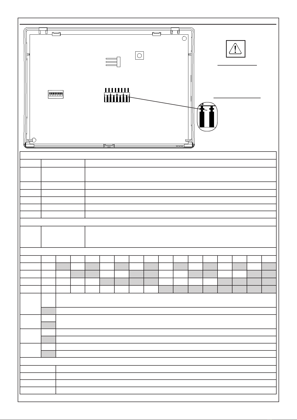
Lignes d’entrée : No 32 lignes congurables avec détection automatique de l’état d’alarme et
d’anti-sabotage programmable individuellement ; chaque entrée peut être
programmée selon l’une des modalités de fonctionnement possibles.
Bornes T1 - T2 n° 2: entrée / sortie
Les bornes T1 et T2 peuvent être programmées soit comme une zone d’entrée 7
et 8 de la zone satellite avec équilibrage individuel (alarme uniquement) ou double
équilibrée (alarme et toucher), les deux sorties de collecteurs ouverts que 7 et 8
avec référence à négative; ou les deux programmes simultanément (entrée ligne est
déséquilibrée directement par l’activation de l’OC correspondant)
Fréquence 868 MHz monofréquence
Portée en plein champ ~ 150 mètres
Programmation: à partir du clavier à l’aide de menus-guides
Connexions: Par quatre conducteurs
Dimensions (L x H x P): 119 x 83 x 10 mm
Boîtier (L x H x P) 129,5 x 92 x 15,5 mm
Conditions ambiantes: +5 °C / +55 °C
Tension: nominale d’alimentation: 13,8 V =
Courant absorbé: Au repos: 30 mA / Pendant la réception: 45 mA / Pendant la transmission: 70 mA
Degré de protection: IPX0
Compatibilité XSAT WS2 avec les centrales AVS Electronics
• Logitel8 Plus Advance (à partir de la version 2.1)
• ADVANCE88
• Concorde Plus 54
• Xtream 640 - 64 - 32 - 6
Avec ces centrales, l’on peut programmer, afcher et contrôler constamment toutes les fonctions relatives au XSAT
WS2 et aux capteurs par voie radio. La centrale est en mesure de reconnaître directement, sur la connexion sérielle
RS 485, toutes les alarmes de zone, de sabotage, ainsi que toutes les informations techniques liées aux appareils
radio (anti-masquage des capteurs, survie des capteurs, faible batterie des capteurs et interférence radio).
Le satellite doit être installé à une distance d’au moins 20 cm par rapport aux boîtiers métalliques ou
aux appareils électriques susceptibles de perturber son fonctionnement.
L’alimentation doit provenir d’un circuit à très basse tension de sécurité et ayant les caractéristiques d’une
source à puissance limitée protégée par un fusible.
L’INSTALLATION ET L’ENTRETIEN DOIVENT ÊTRE EFFECTUÉES PAR UN PERSONNEL QUALIFIÉ

- 11 -
Carte satellite XSATWS 2
INSERTION DES CÂBLES
Dénuder le câble sur 3 - 4 mm et l’in-
sérer dans le bornier correspondant
en créant une légère pression.
DÉSINSERTION DES CÂBLES
Créer une pression légère
avec un tournevis plat
au point indiqué dans le
dessin et – simultaném-
ent – extraire le câble de
son siège
BORNIER
+ RED Positif d’Alimentation
DA
DB
JAUNE
GREEN Connexion RS485
- BLACK Négatif d’alimentation
T1 BLANC Gère l’entrée couplée à la zone 7 et / ou de sortie de collecteur ouvert combinée OC 7
T2 BLEU Gère l’entrée couplée à la zone 8 et / ou de sortie de collecteur ouvert combinée OC 8
T GRAY Tamper entrée (TAMPER) équilibré avec référence à négative.
- VIOLET Négatif
JUMPER
S1
1 - 2
2 - 3
OUVERT
Bouton TAMPER: désactiver - Entrée T: désactiver (permettre l’entrée T libre)
Bouton TAMPER: Enable - Entrée T: désactiver (permettre l’entrée T libre)
Bouton TAMPER: Enable - Entrée T: activé
DIP SWITCH
SAT1 SAT2 SAT3 SAT4 SAT5 SAT6 SAT7 SAT8 SAT9 SAT10 SAT11 SAT12 SAT13 SAT14 SAT15 SAT16
DIP 1 Off On Off On Off On Off On Off On Off On Off On Off On
DIP 2 Off Off On On Off Off On On Off Off On On Off Off On On
DIP 3 Off Off Off Off On On On On Off Off Off Off On On On On
DIP 4 Off Off Off Off Off Off Off Off On On On On On On On On
DIP 5 Off Le satellite est vu par la centrale comme s’il y avait deux satellites dotés d’une adresse séquentielle
qui gèrent jusqu’à 16 capteurs chacun
On Le satellite gère jusqu’à 32 capteurs
DIP 6 Off Non utilisé
On
DIP 7 Off Disable the input link to zone n° 7 e zone n° 8
On Enable the input link to zone n° 7 e zone n° 8
DIP 8 Off modalité XTREAM
On modalité HIGH SPEED
LED MULTICOLOR
LED BLANC Allume quand l'antenne A est en réception
LED VERT Allume lorsque l'antenne B est dans la réception
LED ROUGE Allume quand l'antenne A est dans la transmission
LED BLEU Allume quand l’antenne B est dans la transmission
ON
1 2 34 5 6 7 8
TAMPER
S1
1
1
2
3
-
T
T2
T1
-
DB
DA
+
ON
1 2 34 5 6 7 8

- 12 -
Fonctionnement
En fonction du type de centrale auquel il est combiné, XSAT WS2 peut gérer:
• jusqu’à un maximum de 32 capteurs radio
• jusqu’à 64 télécommandes
• n°1 sirène radio
• La saisie et la programmation des différents accessoires radio s’effectuent par l’entremise du clavier ou du
logiciel prévu à cet effet.
• Chaque installation supporte une seule sirène radio (de version 2.0 ou ultérieure), qui doit nécessairement être
mémorisée sur la première zone du satellite XSAT WS2 qui la gère, de manière à ce que les indications tech-
niques et d’alarme de la sirène soient signalées comme étant relatives au capteur 1 du satellite (dans la sirène
radio, paramétrer le cavalier S2 en position “C”).
• Pour activer et désactiver la sirène en alarme, dans la centrale, la sortie relais relative au satellite où celle-ci a
été mémorisée doit être programmée.
• Il est possible d’activer des signaux optiques de la part du ash de la sirène et télécommande (BIP2PLUS), en
programmant de manière appropriée les sorties Open Collector 2, 3 et 4 du satellite où celle-ci a été mémorisée :
O.C. 2
Le ash de la sirène émet un clignotement “centrale allumée” quand la sortie Open Collector s’active et un
clignotement “centrale éteinte” lorsqu’elle se désactive. BIP 2 Plus: quand O.C. est activé, la LED rouge
allumée et le buzzer retentit et lorsque le oc est désactivé le voyant vert et le signal sonore retentit deux
bips courts
O.C. 3
Le ash de la sirène émet un clignotement “centrale allumée” quand la sortie Open Collector s’active et
aucun lorsqu’elle se désactive. BIP 2 Plus: quand O.C. est activé, la LED rouge allumée et le buzzer re-
tentit et lorsque le oc est désactivé rien arriver.
O.C. 4
Le ash émet un clignotement “centrale allumée” quand la sortie Open Collector s’active et aucun lor-
squ’elle se désactive. BIP 2 Plus: quand O.C. est activé, la LED vert allumée et le buzzer retentit et lor-
sque le oc est désactivé rien arriver.
• Avec certains modèles plus évolués de centrale, pour la programmation de la sirène radio également, se référer
uniquement à ce qui est indiqué dans le manuel de la centrale.
Informations en conformité avec la Directive 1999/5/CEE (R&TTE)
Le produit faisant l’objet de la présente déclaration est conforme aux prescriptions fondamentales de la Directive
1999/ 5/CEE (R&TTE) sur les appareils émetteurs-récepteurs de faible puissance et sur l’utilisation des fréquences
du spectre radioélectrique, et ce également en accord avec la recommandation CEPT 70-03.
Déclaration de conformité
Par la présente AVS Electronics S.p.A. déclare que XSATWS 2 est conforme aux exigences essentielles
et autres dispositions pertinentes prévues par la directive 2004/108 / CE et est conforme à la norme
européenne EN50131.
Déclaration de conformité
peut être téléchargé à l’adresse suivante
: http://www.avselectronics.com/
it/software
ou en utilisant ce QR Code
Marque AVS ELECTRONICS
Modèle XSATWS 2
Fréquence de travail 868 MHz
Type d’alimentation Courant continu
Tension nominale 13,8 V =
Courant nominal 30 mA au repos
45 mA pendant la réception
70 mA pendant la transmission
Pays de la Communauté Européenne où il est destiné à être utilisé Pas de restrictions dans les pays de l’UE
Date 06/07/2015
L’AVS ELECTRONICS S.p.a. se réserve le droit d’apporter des modications à tout moment et sans préavis

- 13 -
IST0886V2.3
Das Produkt mit der CE-Richtlinie über elektromagnetische Verträglichkeit
SATELLITE RADIO BOARD
XSATWS 2
UNI EN ISO 9001:2008
CERTIFIED
QUALITY SYSTEM
Via Valsugana, 63
35010 (Padova) ITALY
Tel. 049 9698 411 / Fax. 049 9698 407
www.avselectronics.com
assistenza tecnica 049 9698 444
D
E
U

- 14 -
XSATWS 2 ERWEITERUNG
Installationsanleitung
ALLGEMEINE INFORMATIONEN
• Der XSAT WS 2 Funkempfänger bildet die Schnittstelle zwischen der verkabelten Zentrale und den verschiede-
nen Funkkomponenten (Sensoren, Signalgeber und Fernbedienungen). Er bietet die Möglichkeit die Reichweite
eines zu überwachenden Bereiches zu erhöhen.
• Das Modul ist in einem Kunststoffgehäuse verbaut, welches seine Leistung optimiert.
• Abhängig von den Anforderungen an das System, kann das XSAT WS 2 auch abgesetzt von der Zentrale montiert
werden. Verbunden werden die beiden Komponenten mittels serieller RS485 Schnittstelle.
• Verwaltung bis zu 32 Funk-Sensoren
• Verwaltung bis zu 64 Fernbedienungen
• Verwaltung 1 Funksignalgeber
• 2 Eingang oder Ausgang Anschlussklemmen
• Mehrfarbige LED-Anzeige
TECHNISCHE DATEN
Eingangslinien 32 kongurierbare, mit automatischer Detektion durch individuell program-
mierbaren Alarm und Sabotage Status; jeder Eingang kann in einen der mög-
lichen Betriebsarten programmiert werden.
Anschlüsse T1 und T2 2: Eingang / Ausgang.
Die Anschlüsse T1 und T2 können entweder als Eingänge Zone 7 und Zone 8
des Satelliten, mit Einzelabgleich (nur Alarm) oder Doppelabgleich (Alarm
und Sabotage) programmiert werden, oder als Open-Collector-Ausgänge 7
und 8, mit Bezug auf negativ, oder beide Optionen gleichzeitig (Linien-Ein-
gang ist unausgeglichen direkt durch Aktivierung des entsprechenden OCs).
Frequenz 868 MHz Einzel-Frequenz
Reichweite (im freien Feld) ~ 150 Meter
Programmierung mittels Bedienteil, menügeführt
Verkabelung vieradrig
Abmessungen Platine (L x B x H ) 119 x 83 x 10 mm
Abmessungen Gehäuse (L x B x H) 129,5 x 92 x 15,5 mm
Betriebstemperatur +5 °C bis 55 °C
Versorgungsspannung 13,8 V =
Stromaufnahme in Ruhe: 30 mA / in Empfang: 45 mA / in Übertragung: 70 mA
Schutzart IPX0
XSAT WS2 KOMPATIBILITÄT MIT AVS ELECTRONICS ZENTRALEN
• Logitel8 Plus Advance (from vers.2.1)
• ADVANCE88
• Concorde Plus 54
• Xtream 640 - 64 - 32 - 6
Mit diesen Zentralen können alle Funktionen des XSAT WS 2 Satelliten und die Funksensoren programmiert,
angezeigt und überwacht werden. Durch die serielle RS485 Verbindung erkennt das System direkt alle Zonen und
Sabotage Alarme und alle technischen Informationen in Verbindung mit den Funk Komponenten (Sensor Abdecküb-
erwachung, Sensor Verfügbarkeit, Sensor Batteriezustand und Funkstörungen).
Der Sender muss mindestens 20cm entfernt von elektrischen Geräten oder metallischen Gegenständen
installiert werden um einen störungsfreien Betrieb zu gewährleisten.
Die Spannungsversorgung muss von einer Sicherheitsniederspannungsschaltung kommen, mit den Eigen-
schaften einer begrenzten Spannungsversorgung, durch eine Sicherung geschützt.
INSTALLATION UND WARTUNG MÜSSEN VON QUALIFIZIERTEM PERSONAL VORGENOMMEN WERDEN

- 15 -
SATELLITEN PLATINE XSATWS 2
VERDRAHTUNG
Das Kabel für 3 - 4 mm abisolieren
und mit leichtem Druck in die ent-
sprechende Klemme einfügen.
KABEL ENTFERNEN
Drücken Sie mit einem
Schraubendreher leicht
an den in der Abbildung
angegebenen Punkt und
ziehen Sie gleichzei-
tig das Kabel aus dem
Gehäuse heraus
ANSCHLUSSKLEMMEN
+ ROT positive Spannung
DA
DB
GELB
GRÜN DA /DB RS485 serielle Verbindung
- SCHWARZ negative Spannung
T1 WEISS
verwaltet den Eingang in Verbindung mit Zone Nr. 7 und / oder Open Collector Ausgang (OC 7)
T2 BLAU
verwaltet den Eingang in Verbindung mit Zone Nr. 8 und / oder Open Collector Ausgang (OC 8)
T GRAU Sabotageeingang (TAMPER) mit Bezug auf die negativen ausgeglichen.
- VIOLET negativ
JUMPER
S1
1 - 2
2 - 3
OFFEN
SABOTAGE Taster: DEAKTIVIERT: - Eingang T: DEAKTIVIERT (ermöglichen freien eingang T)
SABOTAGE Taster: AKTIVIERT: - Eingang T: DEAKTIVIERT (ermöglichen freien eingang T)
SABOTAGE Taster: AKTIVIERT: - Eingang T: AKTIVIERT
DIP SWITCH - Empfänger Adresse
SAT1 SAT2 SAT3 SAT4 SAT5 SAT6 SAT7 SAT8 SAT9 SAT10 SAT11 SAT12 SAT13 SAT14 SAT15 SAT16
DIP 1 Off On Off On Off On Off On Off On Off On Off On Off On
DIP 2 Off Off On On Off Off On On Off Off On On Off Off On On
DIP 3 Off Off Off Off On On On On Off Off Off Off On On On On
DIP 4 Off Off Off Off Off Off Off Off On On On On On On On On
DIP 5 Off Der Controller sieht den Satelliten als zwei Satelliten mit aufeinanderfolgenden Adressen. Jeder
Satellit kann bis zu 16 Sensoren verwalten.
On Der Satellit verwaltet bis zu 32 Sensoren
DIP 6 Off Nicht benutzt
On
DIP 7 Off Deaktivieren Sie die Verwaltung der Eingänge in die Zone 7 und Zone 8 gekoppelt
On Ermöglicht die Verwaltung von Eingaben in die Zone 7 und Zone 8 gekoppelt
DIP 8 Off XTREAM Modus
On HIGH SPEED Modus – zu verwenden bei Verdrahtung über RS485
MEHRFARBEN LED
WEISSE LED Leuchtet auf, wenn die Antenne A empfängt
GRÜNE LED Leuchtet auf, wenn die Antenne B empfängt
ROT LED Leuchtet auf, wenn die Antenne A überträgt
BLAU LED Leuchtet auf, wenn die Antenne B überträgt
ON
1 2 34 5 6 7 8
TAMPER
S1
1
1
2
3
-
T
T2
T1
-
DB
DA
+
ON
1 2 34 5 6 7 8

- 16 -
BETRIEB
• In Abhängigkeit des eingesetzten Zentralentyps kann das XSAT WS 2:
• bis zu 32 Funk-Sensoren
• bis zu 64 Fernbedienungen
• 1 Funksignalgeber verwalten.
• Die verschiedenen drahtlosen Komponenten werden über das Bedienteil oder der speziellen Software erkannt
und programmiert.
• Jedes System unterstützt einen Funksignalgeber (Version 2.0 oder höher), welche in die erste Zone des XSAT
WS 2 Satelliten eingelernt werden muss der sie verwaltet; auf diesem Weg werden die technischen Alarme und
die Alarmsignale des Signalgebers übertragen als Bezug zu Sensor 1 des Satelliten (in dem Signalgeber muss
der Jumper S2 in Position „C“).
• Zur Aktivierung und Deaktivierung des Signalgebers bei Alarm, muss der entsprechende Relaisausgang des
Satelliten in der Zentrale programmiert werden.
• Die optische Signalisierung (Blitz) und der BIP 2 Plus werden durch die Programmierung der OC Ausgänge 2,
3 und 4 des jeweiligen Satelliten aktiviert:
O.C. 2
Der Signalgeber gibt einen “Zentrale scharf”-Blitz wieder wenn OC aktiviert wird und ein “Zentrale un-
scharf”-Blitz bei OC Deaktivierung.
BIP 2 Plus: Wenn der OC aktiviert wird leuchtet die rote LED auf und der Summer ertönt und bei OC De-
aktivierung leuchtet die grüne LED und der Summer ertönt zweimal kurz.
O.C. 3
Der Signalgeber gibt einen “Zentrale scharf”-Blitz wieder wenn OC aktiviert wird und es passiert nichts bei
OC Deaktivierung.
BIP 2 Plus: Wenn der OC aktiviert wird leuchtet die rote LED auf und der Summer ertönt und bei OC De-
aktivierung passiert nichts.
O.C. 4
Blitz bei “Zentrale scharf” wenn OC aktiviert wird und es passiert nichts bei Deaktivierung.
BIP 2 Plus: Wenn der OC aktiviert wird leuchtet die grüne LED auf und der Summer ertönt zweimal kurz
und bei OC Deaktivierung passiert nichts.
• Die Programmierung der Funksignalgeber in Verbindung mit weiteren Zentralen ist in dem entsprechenden
Handbuch der Zentrale nachzulesen.
Information gemäß der Richtlinie 1999/5 / cee (r & tte)
Das hier beschriebene Produkt entspricht im Wesentlichen den Vorschriften der Richtlinie 1999/5 / CEE (R&TTE)
über Funkübertragungseinrichtungen niedriger Leistung und die Verwendung von Frequenzen des funkelektrischen
Spektrums, entsprechend CEPT 70-03 Empfehlung.
KONFORMITÄTSERKLÄRUNG
AVS Electronics S.p.A. erklärt hiermit, dass der XSAT WS 2 mit den grundlegenden Anforderungen
und anderen relevanten Bestimmungen der Richtlinie 2004/108 / EC und mit der Europäischen Norm
EN50131 übereinstimmt.
Die Konformitätserklärung kann unter folgendem Link eingesehen werden: http://www.avse-
lectronics.com/it/software oder mit durch Nutzung dieses QR CODES
Hersteller AVS ELECTRONICS
Modell XSATWS 2
Arbeitsfrequenz 868 MHz
Spannungsversorgung Direkte Versorgung
Nennspannung 13,8 V =
Stromaufnahme 30 mA (in Ruhe)
45 mA (in Empfang)
70 mA (in Übertragung)
Länder in der Europäischen Gemeinschaft in der es verwendet wird Keine Einschränkungen in EU-Ländern
Datum 06/07/2015
L’AVS ELECTRONICS S.p.a. behält sich das Recht vor, Änderungen jederzeit und ohne vorherige Ankündigung vorzunehmen
Table of contents
Languages:
Other AVS Electronics Transceiver manuals