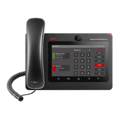
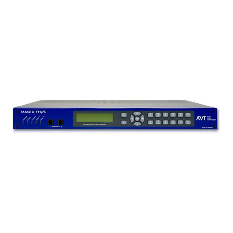
AVT MAGIC TH1 potsGo User manual

MAGIC TH1 potsGo
MAGIC TH1 ipGo
Configuration Guide
Version V1.400
1
© by AVT Audio Video Technologies GmbH

Basic Configuration
2
Connect your MAGIC TH1 system via the LAN
interface to your IP network
The easiest way to obtain a valid IP address is to
activate DHCP in the system via the front panel
▪Press the softkey MENU and select LAN INTERFACE
→ DHCP and set the checkbox ENABLE
▪Press the DROP key and save the configuration
▪The assigned IP address is visible by pressing the
DROP key again
Alternatively, you can set the desired IP address,
subnet mask, etc. manually under the LAN
INTERFACE menu item
Open now your web browser and enter the IP
address of the MAGIC TH1 system
▪You can also use the system name TH1go instead of
the IP address if DNS is available
If everything is correct the main window appears
Softkey MENU DROP key

3
Main Window
Actual
connection
status of
MAGIC TH1
Opens
Configuration Menu

Operating Elements (1)
4
❶Menu
❷Own SIP number
❸Connection & system status
❹Caller information
❺Dial keypad
❻Telephone book
❼Delete caller information
❽Save caller information
❾Phone number of caller
❿Name of caller
⓫Information of caller
❶ ❷ ❸
❹ ❺ ❻
❼
❽
❾
❿
⓫

Operating Elements (2)
5
❶System Name
❷PRETALK –Telephone in use
❸PRETALK –Audio XLR in use
❹HOLD
❺ON AIR
❻Disconnect line
❼Transfer call
❽AGC Automatic Gain Control on/off
❾Level adjustment
❿Level meter
⓫VD Voice Disguise on/off
⓬Audio in HD Voice (7-kHz) received
❶
❷❹ ❺ ❻ ❼
❽
⓫
⓬
❿
❸❾

Settings
General
Line Interface
Audio
Operation
Signal Processing
LAN Interface
VLAN
GPIO (TTL/Relay)
6

General Settings
7
Display Language
▪Select English or German
Front Keypad Key Tone
▪If Front Keypad Key Tone is selected a tone is
generated after pressing a button on the key panel
Backlight
▪One of the following modes can be selected:
Permanent On
Auto-switch off: on only during key entries
Display Contrast
▪The display contrast can be adjusted in a range
between -4 … +4
System Name
▪The System Name is displayed in the main window
which is helpful if you have more than one TH1 system
in use
▪The system can be also used instead of the IP address
in a web browser (default: TH1go)

Line Interface Settings
8
Under →Line Interface the line
interface settings can be configured
Select under Line Mode which interface
you want to use
(the availability depends on your system
and enabled options)
▪POTS
▪VoIP

POTS Mode (1)
9
Your Country
▪If you use landlines: Country of your location
▪If you use a PBX: Try first your country or alternatively
the country of origin of the PBX
Note that this setting is essential for correct operation of the
built-in digital echo canceller. When you hear echoes, the
cause is usually a misadaptation of the impedance, which is
determined by the country setting.
Outgoing Line Prefix
▪If the system is connected to a PBX, you can enter the
Outgoing Line Prefix, e.g. 0, which is automatically
added if you dial an external number
Inside Phone number length
▪The outgoing line prefix is dialled automatically if you
dial a number that is longer than the number length
specified here
▪If you work with landlines, please select 0
Skip outgoing line prefix on incoming calls
▪If the phone number is displayed in the software with
outgoing line prefix, the outgoing line prefix is deleted
and the displayed telephone number can be saved
directly to the phone book
POTS
mode
selected


POTS Mode (2)
10
Wait for CLIP before call in signalling
▪If selected, an incoming call is not displayed until the
caller's phone number has been recognized (CLIP
function). If no phone number is signaled, the call is
displayed after a short time.
Drop when busy tone detected
▪Automatic drop after detection of the busy tone
This function requires to Start the function Measure
BUSY/DROP tone
Loop-Break Timeout
▪The loop current can be interrupted for that time period
without interrupting the connection
Hook Flash Duration
▪The length of the pulse which is necessary for call
forwarding. It is also a interruption of the loop current

POTS Mode (3)
11
The values for BUSY/DROP Tone Duration and
BUSY/DROP Pause Duration can be set manually,
but we strongly recommend using the built-in
measurement function.
Measure BUSY/DROP tone
▪Enter your own phone number and press Start
▪The values for BUSY/DROP Tone Duration and
BUSY/DROP Pause Duration are automatically adjusted
▪With that settings the system recognises when a caller drops
the line or if the line is busy
Line Level Adjustment: Receive
▪Receive Line Level can be adjusted from -9 to +9 dB
Change this setting only if the caller level is always too low
Line Level Adjustment: Transmit
▪Transmit Line level can be adjusted from -9 to +9 dB
Change this setting only if the callers can always hear you poorly.
High Pass Filter Cut OFF Frequency: Receive
▪High path filter for the reduction of disturbances
▪In particular, if you hear a humming noise on the line, set a
higher cut-off frequency (e.g. 100 Hz)

VoIP Mode (1)
12
SIP Server
▪Enter the name or IP address of the SIP Server
A name requires a valid DNS entry under LAN settings
SIP Transmission Protocol
▪Select UDP or TCP/IP according to the requirements of
the VoIP provider
DTMF Tx Type
▪Select Inband (In Audio) or RTP (RFC2833) according
to the requirements of the VoIP provider
User Name
▪Enter your User Name (typically the phone number)
provided by the VoIP provider
User Authentication
▪Enter the User Authentication provided by the VoIP
provider or leave it blank if it is not specified
Password
▪Enter Password provided by the VoIP provider
VoIP
mode
selected

VoIP Mode (2)
13
Audio UDP Port
▪Change only if necessary
Display Name
▪The Display Name is only displayed at the receiving side,
subject to the condition that the function is supported by the
telephone and the SIP Server
STUN
▪Enable STUN only if required by the VoIP provider. In this
case a STUN Server must be configured
STUN Server
▪Enter name or IP Address of the STUN Server
A name requires a valid DNS entry under LAN settings
NAT KeepAlive Message Time
▪Time to open the STUN Server for communication
Payload Time
▪In the system the Payload Time is set to 10 ms by default to
minimise the overall latency
If you experience Audio dropouts increase the payload to
20 ms, which is usually used by VoIP telephones

VoIP Mode (3)
14
QoS Voice and QoS SIP
▪If your network offers Quality of Service (QoS), please enter
the correct values under QoS Voice (default: 184) and QoS
SIP (default: 104)
We expect here the so called Diff Serv values
Outgoing Line Prefix
▪If the system is connected to a PBX, you can enter the
Outgoing Line Prefix, e.g. 0, which is automatically added if
you dial an external number
Inside Phone number length
▪The outgoing line prefix is dialled automatically if you dial a
number that is longer than the number length specified here
▪If you work with landlines, please select 0
Skip outgoing line prefix on incoming calls
▪If the phone number is displayed in the software with
outgoing line prefix, the outgoing line prefix is deleted and the
displayed telephone number can be saved directly to the
phone book

Audio Interfaces (1)
15
Pretalk Interface
▪Select here the desired Pretalk Interface:
Not used
Telephone
Pretalk (XLR)
Telephone + Pretalk (XLR)
Telephone with control
▪If selected the telephone can operate the hybrid via DTMF tones,
e.g. switch to ON AIR, activate AGC etc.
Hold Signal Source
▪The HOLD signal can be generated from the following sources:
ON AIR in (XLR)
HOLD in (XLR)
Recorded Hold Signal
Pause between repetition
▪If Recorded Hold Signal is set as HOLD signal source, a Pause
between Repetition can be defined
HOLD Signal duration
▪After loading the Recorded Hold Signal file via the Load file
button the HOLD signal duration will be displayed in seconds
The format of the WAV file must be: 8-kHz/Mono/16 Bit

Audio Interfaces (2)
16
Monitoring Out (XLR)
▪The monitoring output is only available if no Pretalk (XLR) is
configured for the Pretalk Interface
▪You can choose between the following settings
not used
Caller
Caller + Presenter
Level In
▪Nominal Level of the analogue input
▪Adjustable in a range from -3 to +9 dBu (default: +6 dBu)
Level Out
▪Nominal Level of the analogue output
▪Adjustable in a range from -3 to +9 dBu (default: +6 dBu)
Audio Headroom
▪Headroom of the of the analogue audio interface
▪Adjustable in a range from 0 to 15 dBr (default: +9 dBr)
Pretalk Telephone Audio Level
▪Audio Level to the optional connected POTS telephone
▪Adjustable in a range from -12 to +12 dB

Operation (1)
17
Enable System Ringing Tone
▪If activated, the system internal buzzer signals
incoming calls
Front Keypad Control of Line State
Switching the line status (e.g. Pretalk, Hold, On Air etc.) via the
front keypad can be configured in three different ways:
▪Standard
Standard function as labelled on the keys
▪Numerical Keypad
No connection → Standard function as labelled on
the keys
Connection established:
1→ PRETALK/PHONE
2→ HOLD
3→ ON AIR
7→ Redirect Call (R)
→ DROP
▪Softkeys
The two softkeys allows a direct switching between
ON AIR and DROP
PRETALK
PHONE
HOLD
ON AIR
DROP
REDIRECT
(R)
DROP
ON AIR
Mode
SOFTKEYS
Mode
NUMERICAL
*

Operation (2)
18
Enable Voice Disguise
▪If activated, Voice Disguise is enabled
Voice Disguise Pitch
▪As pitch can be selected
Up for a shift to higher frequencies
Down for a shift to lower frequencies
Voice Disguise Ratio
▪The strength of the pitch shift can be adjusted in the range
from 1 (low) ... 4 (high)
Auto Answer Call on Audio Line
▪This activates automatic call answering for incoming calls.
You can choose:
Not used to disable the function
Switch caller to HOLD
Switch caller to ON AIR
Auto Answer Delay
▪This function can be used to delay automatic call answering
in the time range of 0 ... 31 seconds.
During this time, an incoming call is signaled as usual by
ringing and/or flashing

Signal Processing (1)
19
Automatic Gain Control
If the integrated Automatic Gain Control is switched
On, the function can be configured via three
parameters
▪The Threshold value determines the level when
the AGC should start work
Range: -45 .... -35 dBFS
Recommended: -40 dBFS
▪The Level parameter defines the target level
Range: -30 .... -20 dBFS
Recommended: -25 dBFS
▪The Speed selection defines how fast the AGC
should work. Values are:
Slow, Medium, Fast
Recommended: Medium or Slow

Signal Processing (2)
20
Echo Canceller
▪The integrated Echo Canceller can be switched On or Off
Especially callers still using POTS lines can cause a strong
echo. Therefore we always recommend to activate the Echo
Canceller.
The maximum echo tail time is approx. 120 msec. In this time
window the echo canceller can reduce the echo.
Line Basis Delay
▪If the system is connected to a PBX or callers are forwarded
via an external platform, the Line Basis Delay of the (local)
system can be set as the basis value so that a possible echo
falls within the time window of 120 msec in any case.
Range: 0 … 120 msec
Recommended: Landline = 0 msec, PBX > 40 msec
Line Level Offset Attenuation (Send)
▪The send level can be reduced in a range
from -6 dB … -15 dB
If you have problems with echoes you should try to reduce this
level slightly
Table of contents
Other AVT Telephone System manuals
Popular Telephone System manuals by other brands

ITT
ITT 601A manual

AT&T
AT&T DEFINITY Remote Port Security Device user manual

Panasonic
Panasonic KX-TVS50 - 2 Port Voicemail System installation manual

Siemens
Siemens HIPATH 2000 operating instructions

Panasonic
Panasonic KX TS208W operating instructions

Auerswald
Auerswald ETS-4308 I Adapters installation and configuration