Avtech AVX992 User manual
383Z
x992_quick_V0.9
AVX992 DISK ARRAY
USER MANUAL
Please read instructions thoroughly before operation and retain it for future reference.
OVERVIEW
OVERVIEW
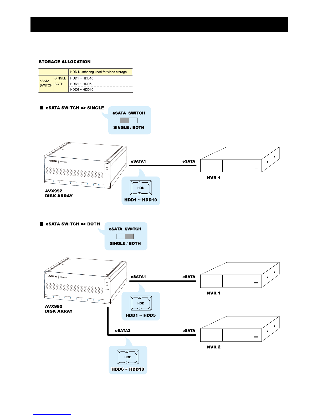
This disk array is a 10-bay storage device with two eSATA ports to connect up to two AVTECH DVRs / NVRs. When
two DVRs / NVRs are connected, please switch to the correct eSATA mode on the rear panel as illustrated below:
OVERVIEW
SPECIFICATIONS
STORAGE
Drive Bay(s) 10
Compatible Drive Type 3.5” SATA HDD, Up to 6TB per drive
External Ports
eSATA YES ( 2 ports, connecting up to two DVRs / NVRs for video storage)
RS485 YES
General
LED Indicators Power / Fan Error / HDD Status
Operating Temperature 10℃~ 40℃(50℉~104℉)
Storage Temperature 70℃
Power Source DC19V / 180W
Power Consumption
(without a hard disk connected) 11.5W
Dimensions(mm)* 325.5 (L) x 281.17 (W) x 138.1 (H)
Weight(kg) 10.6
Optional Accessories Rack mount (AVH516PLUS-RBKT)
*DimensionalTolerance:±5mm ** The specifications are subject to change without notice.
Front Panel
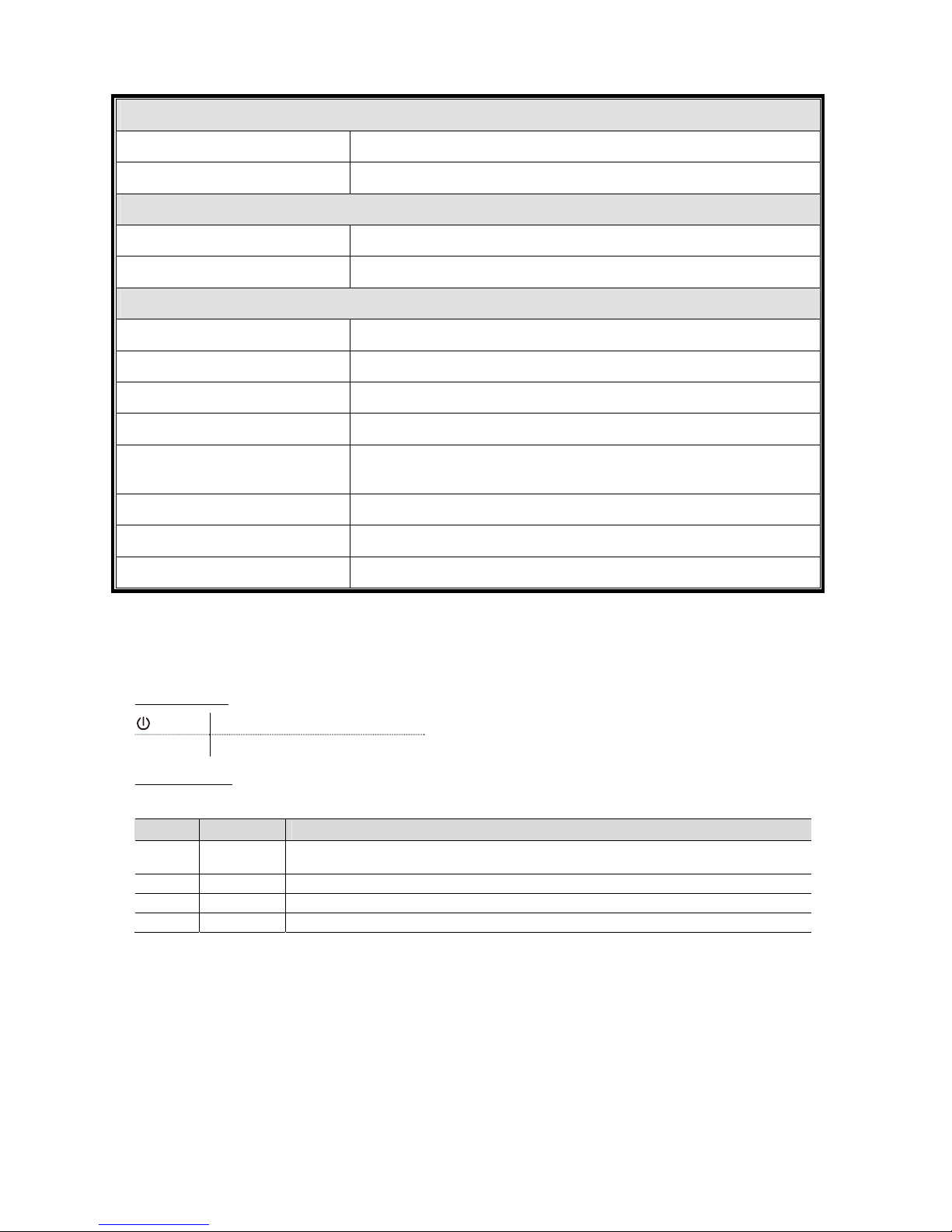
1) LED indicators
This device is power-supplied.
Fan error A fan works abnormal.
2) HDD Indicators
Check the HDD indicator for each installed hard disk to ensure the hard disks work normally.
Color Status Meaning
-- No light No hard disk is installed, or the installed hard disk is not detected. Please install a hard disk or
replace the installed hard disk, and try again.
Green Always on The installed hard disk is detected well.
Green Flashing Data reading / writing.
Red Always on The installed hard disk is failed. Please replace the installed hard disk, and try again.
OVERVIEW
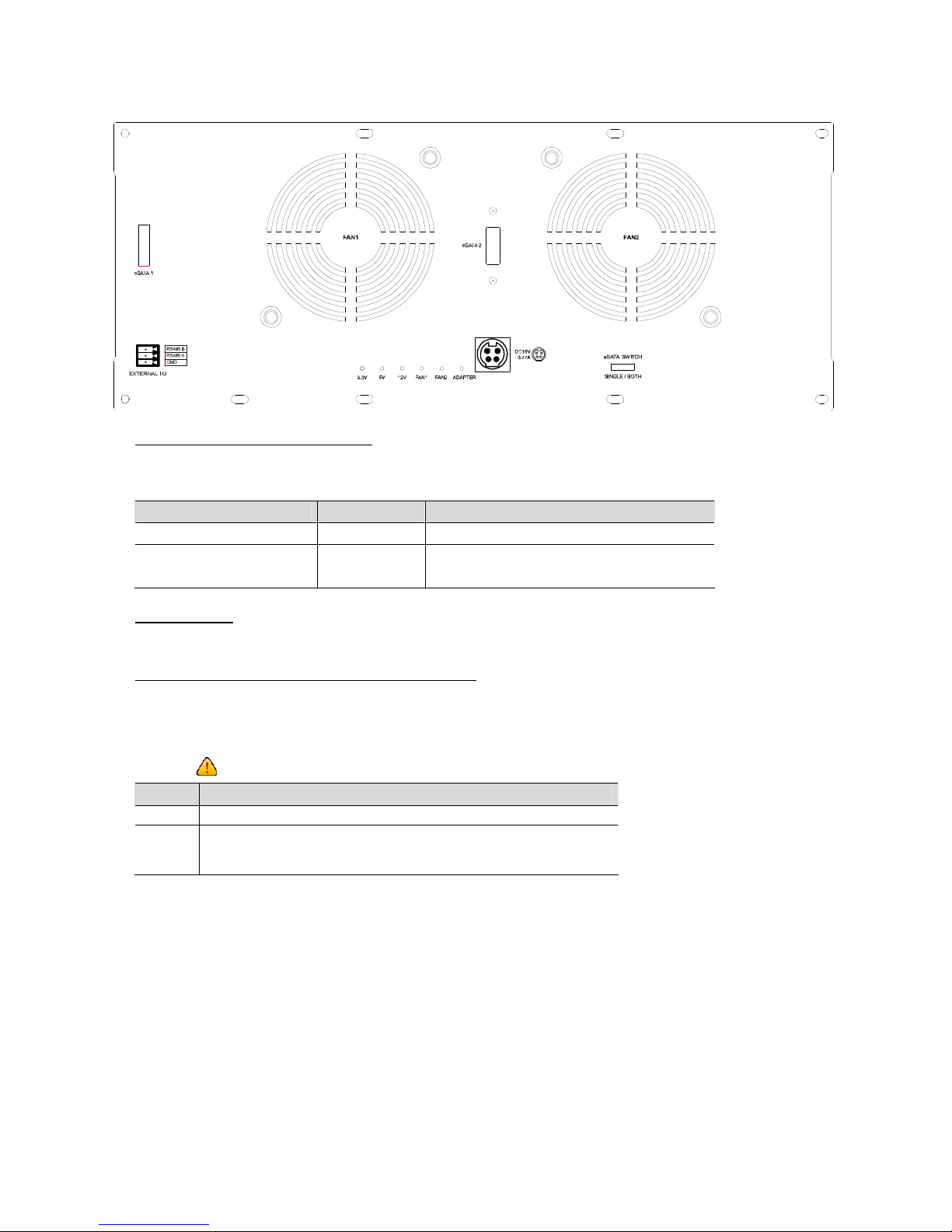
Rear Panel
1) eSATA 1, eSATA 2 & eSATA SWITCH
This disk array could be connected to two NVRs / DVRs for video storage. To know how to switch the mode,
please check the table below or refer to the section, <OVERVIEW>:
eSATA SWITCH turns to… Connect to… HDD number to be used for video storage
SINGLE eSATA1 1 ~ 10
BOTH eSATA1 1 ~ 5
eSATA2 6 ~ 10
2) EXTERNAL I/O
Insert the supplied external I/O block, and users are able to connect external devices.
3) LED indicators for adapters, fans, and power modules
There are indicators for FAN, ADAPTER, and power modules (3.3V / 5V / 12V) for users to diagnosis the status of
fans, adapters and power modules.
When any of the indicators is red, the ERROR indicator on the front panel will turn red to warm the users. You’ll
also see “ ” on the live view.
Color Meaning
Green OK
Red 1. No use.
2. Something's wrong with any of the fans, adapters, or power modules.
Please check with your installer or distributor for repair if necessary.
INSTALLATION
INSTALLATION
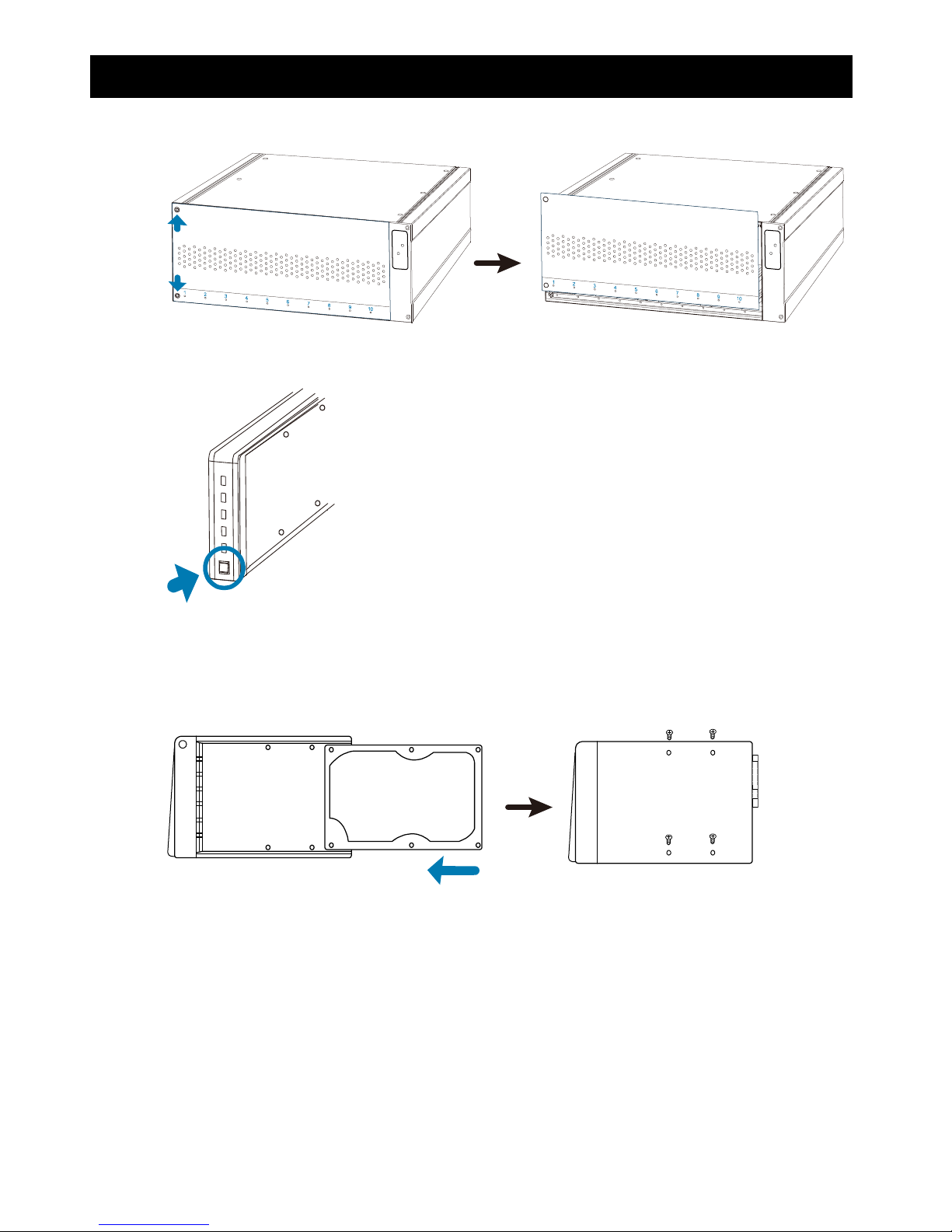
Step1: Remove the cover by loosening the left side of the cover’s screws.
HDD2HDD3HDD4HDD5HDD6HDD7HDD8HDD9HDD10
HDD
12345678910
HDD2HDD3HDD4HDD5HDD6HDD7HDD8HDD9HDD10
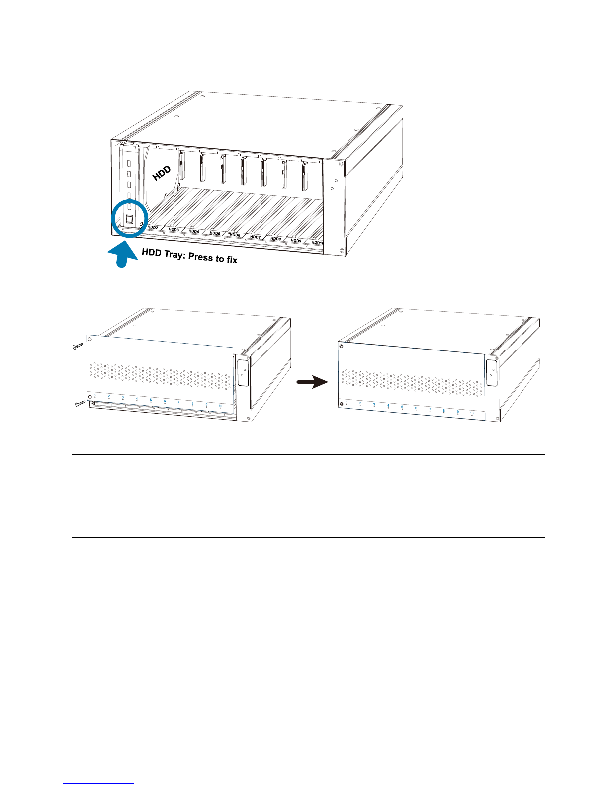
Step2: Find the hard disk connector and HDD tray in the device. Press the button of the HDD tray as indicated
below and remove it.
HDD Tray: Press to remove
Step3: Get a compatible hard disk. With the PCB side facing the internal of the HDD tray and the hard disk‘s
connector facing the outside.
Then, find the HDD screws supplied in the sales package. Align the hard disk’s screw holes with the HDD
tray’s holes and fasten the screws.
HDD
INSTALLATION
Step4: Place the HDD tray to the device, and push it to the end till you feel the hard disk is inserted to the hard disk
connector.
Then, lock the HDD tray as shown below.
Step6: Replace the front cover and fasten the screws you loosened in Step1.
HDD2HDD3HDD4HDD5HDD6H
DD7HDD8HDD9
Step7: Connect to one or two NVRs / DVRs and other devices to build the whole system if needed.
Note: Please make sure the eSATA mode is switched correctly. For details, please check
<OVERVIEW>.
Step8: Power on the whole system and wait till the system initialization is done.
Note: Please power on AVX992 first and then your NVR. Otherwise, the NVR might not detect AVX992
properly.
Then, wait till the HDD indicators turn green. For details, please refer to the section <Front Panel>.
COMPATIBLE HARD DISK LIST
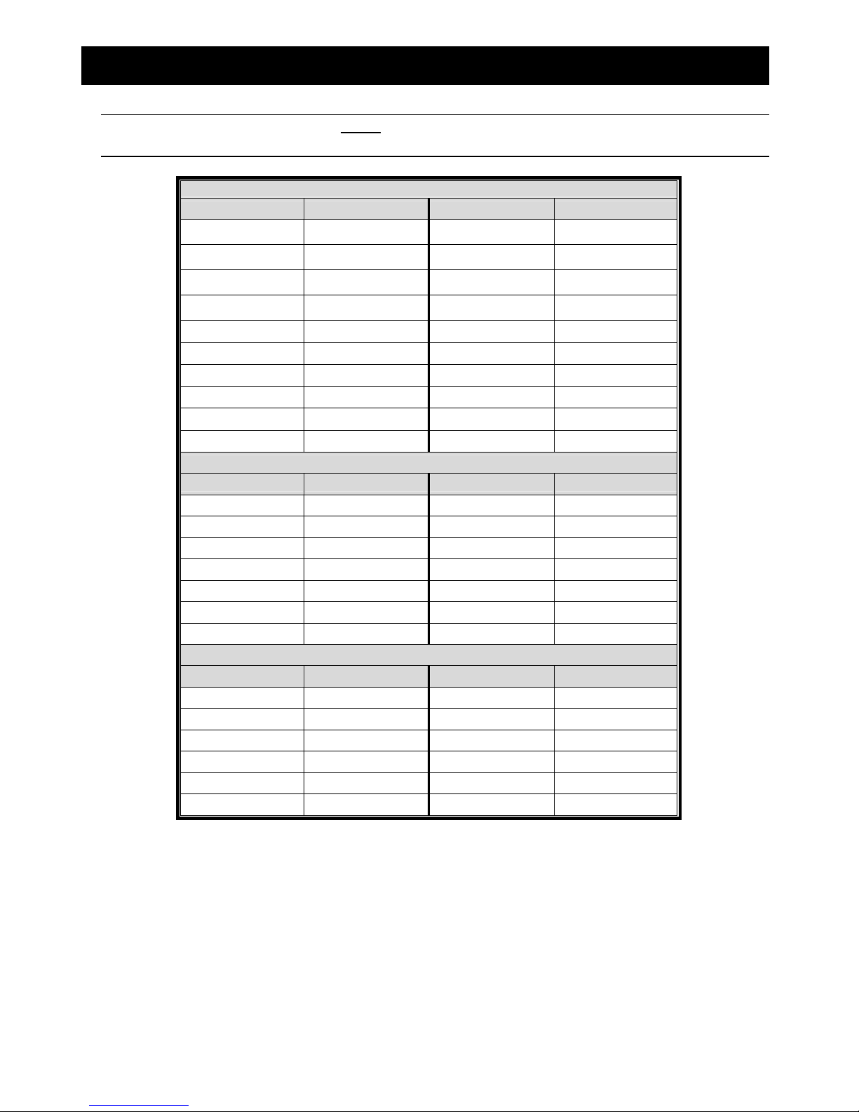
COMPATIBLE HARD DISK LIST
Note: To use a green hard disk, use ONLY the hard disk designed especially for surveillance to ensure
the device works properly.
Seagate*
MODELCAPACITYMODEL CAPACITY
Pipeline HD
ST3500312CSS 500GB ST2000VX004 2TB
Pipeline HD
ST500VT000 500GB ST3000VM002 3TB
Pipeline HD
ST1000VM002 1TB ST3000VX004 3TB
Pipeline HD
ST1000VM002 1TB ST3000VX005 3TB
ST31000525SV 1TB ST3000VX006 3TB
ST31000340AS 1TB ST3000VX000 3TB
ST1000VX000 1TB ST4000VM000 4TB
ST1000VX002 1TB ST4000VX002 4TB
ST2000VX000 2TB ST6000VX0001 6TB**
ST2000DM001 2TB ST6000VX0011 6TB**
WD
MODEL CAPACITY MODEL CAPACITY
WD10PURX 1TB WD30EURX 3TB
WD20PURX 2TB WD30EFRX 3TB
WD20EURS 2TB WD40PURX 4TB
WD20EURX 2TB WD40EURX 4TB
WD20EFRX 2TB WD60EURX 6TB**
WD2002FAEX 2TB WD60PURX 6TB**
WD30PURX 3TB
TOSHIBA
MODELCAPACITYMODEL CAPACITY
DT01ACA050 500GB MD03ACA200V 2TB
DT01ABA050V 500GB DT01ABA300V 3TB
DT01ACA100 1TB DT01ACA300 3TB
DT01ABA100V 1TB MD03ACA300V 3TB
DT01ACA200 2TB MD03ACA400V 4TB
DT01ABA200V 2TB
MD04ABA500V 5TB
Table of contents
Other Avtech Disk Array System manuals


Popular Disk Array System manuals by other brands

Fujitsu
Fujitsu ETERNUS DX60 S2 Maintenance manual

Accom
Accom WSD/2XTREME user guide

HP
HP Compaq Presario,Presario 4400 Quickspecs

ATTO Technology
ATTO Technology Diamond Storage Array V-Class Installation and operation manual

National Instruments
National Instruments RMX-8268 installation guide

Overland Tandberg
Overland Tandberg SnapServer DX1 instructions


