SPECIFICATIONS
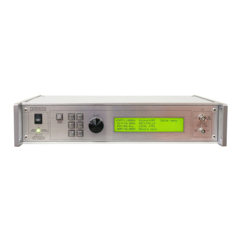
Model: AVRQ-5-B1
High-Voltage Pulse Amplitude:
(HV pulse / GND1)
Standard: -1.5 or +1.5 kV
-AHV9 option: -1 kV to -1.5 kV,
+1 kV to +1.5 kV, in ≤ 1V steps
-XHV10 option: -1.5 kV to - kV,
-1.5 kV to - kV, in ≤ 1V steps
Load resistance: > 10 Megohms (this is not a 50 Ohm system.)
Load capacitance (CLOAD): 0 to ~300 pF. Must be adjusted to obtained the desired transition time.
Load connection style: A pattern of pin sockets into which a daughterboard may be plugged is provided.
Sample daughterboards with 8-pin DIP sockets are included.
The user may also user their own custom-made daughterboards.
Leading edge rise time :
(10% - 90%):
≤ 10 ns (≤ 15 ns with -XHV option10) for CLOAD = 0.
Up to 50 ns, by increasing CLOAD.
Leading edge shape: Approximately linear. See the typical waveform photos on the preceding and following pages.
Trailing edge fall time3 (90%-10%): At least ten times greater than the leading edge rise time. Not adjustable.
Trailing edge shape: Exponential decay, approximately. See the typical waveform photos in this manual.
Pulse width (measured between the
start of the leading edge
and the start of the falling edge):
1 - 0 us, adjustable.
PRF: 10 Hz maximum
VCC1 power supply (input side,
floating, referenced to HV pulse /
GND1):
Not provided by the mainframe. The input side of the daughterboards must be self-powered. The
included sample boards use an A 3-type battery with a low-dropout regulator.
VCC power supply (output side,
referenced to GND chassis ground): +3V to +43V, adjustable. 150 mA maximum.
Logic output pull-up resistance: User-installed, on daughterboard as appropriate
Output connector, HV PULSE: BNC female, suitable for use with the Tektronix P5100 high-voltage probe
and 013-0 91-00 probe-tip-to-BNC adapter
Output connector, logic output: A two-pin header suitable for use with the Tektronix P6 46 differential probe8. Other probes may be
used by installing a matching two-pin socket as an extender.
Output enable timer: The output will only remain active for 90 seconds after the last output parameter update.
After that time, the output will be disabled. The output must be re-enabled
from the front panel or by computer command for the next test sequence.
Propagation delay: ≤ 00 ns (Ext trig in to start of output pulse)
Jitter (Ext trig in to pulse out): ± 00 ps ± 0.03% of sync delay
Trigger modes: Internal trigger, external trigger (TTL level pulse, > 10 ns, 1 kΩ input impedance),
front-panel “Single Pulse” pushbutton, or single pulse trigger via computer command.
Variable delay: Sync to Out: 0 to 1.0 seconds, for all trigger modes (including external trigger).
Sync output: +3 Volts, 100 ns, will drive 50 Ohm loads
Gate input: Synchronous, active high or low, switchable. Suppresses triggering when active.
Other connectors: Trig, Sync, Gate: BNC
GPIB and RS- 3 control: Yes. (Visit http://www.avtechpulse.com/labview for LabView drivers.)
Ethernet port, for remote control
using VXI-11.3, ssh, telnet, & web:
Optional4. Recommended as a modern alternative to GPIB / RS- 3 .
See http://www.avtechpulse.com/options/vxi for details.
Settings accuracy: Not calibrated. Verify the output parameters with a calibrated oscilloscope.
Power requirements: 100 - 40 Volts, 50 - 60 Hz
Dimensions: (H x W x D) 145 x 430 x 475 mm (5.7” x 17” x 18.8”)
Chassis material: cast aluminum frame and handles, blue vinyl on aluminum cover plates
Temperature range: +5°C to +40°C
1) -B suffix indicates IEEE-488. GPIB and RS- 3 control of amplitude, pulse width, PRF and delay (See http://www.avtechpulse.com/gpib/).
) The rise time is affected by the load capacitance. A high-voltage high-bandwidth oscilloscope probe such as the Tektronix P5100 should always be used to verify the
actual output rise time, rather than relying on the programmed value.
3) Refers to the trailing edge, which swings from -1000V or - 000V to 0V
4) Add the suffix -VXI to the model number to specify the Ethernet port.
5) Note that coaxial cabling typically adds 30 pF/ft.
6) The user must install a standard 9V battery in the provided holder, in order to power the floating power supply. The battery is not included, due to shipping regulations.
7) To specify the extended VCC range, add the -SCHB option suffix to the model number.
8) A differential probe is suggested to reduce the possibility of interference from the high-voltage pulse. Note that the P6 46 is only suitable for values of VCC up to +7V.
A non-differential probe may be more suitable if VCC > 7V, or if parasitic inductances or capacitances in the test circuit cause differential voltage spikes exceeding
±7V. The P6 46 can saturate under those conditions, which can generate apparent glitch-like transients that are not due to the DUT. Some experimentation may be
required by the user in order to identify the best probing arrangement.
9) Add the suffix -AHV to the model number to specify the +/- 1 to 1.5 kV (in ≤ 1V steps) operating range.
10) Add the suffix -XHV to the model number to specify the +/- 1.5 to kV (in ≤ 1V steps) operating range. This optiion increases the minimum switching time by 5 ns.
9
