AVTECH Software, Inc. Page 2 AVTECH.com
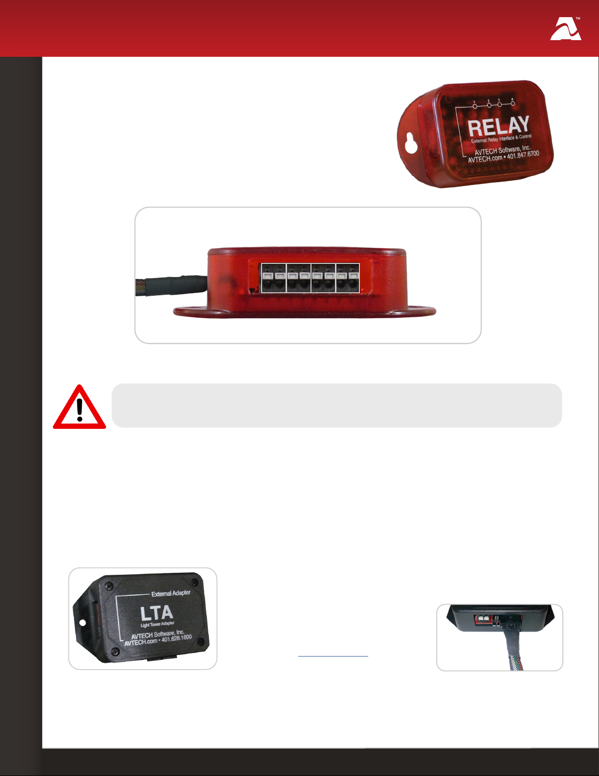
Relay Switch Sensor (RMA-RELAY-SEN)
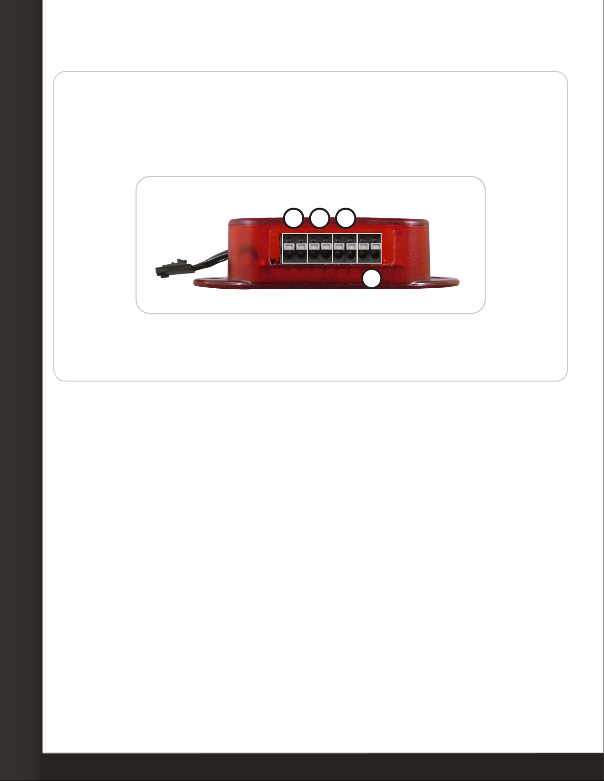
Step 3: Connect a low-voltage device to your Relay Switch.
Disconnect power to the electrical device before beginning.
Do not connect the relay outputs on AVTECH products to live circuits of over 125VAC or
24VDC.
Use an appropriate wire to connect the relay ports to your electrical device; consult an
electrician if you are unsure if the wire is compatible with the electrical load or device.
Use an appropriate wire or cable to connect the relay ports to your electrical device. If
you are unsure if the wire is compatible with the electrical load or device, contact an
electrician.
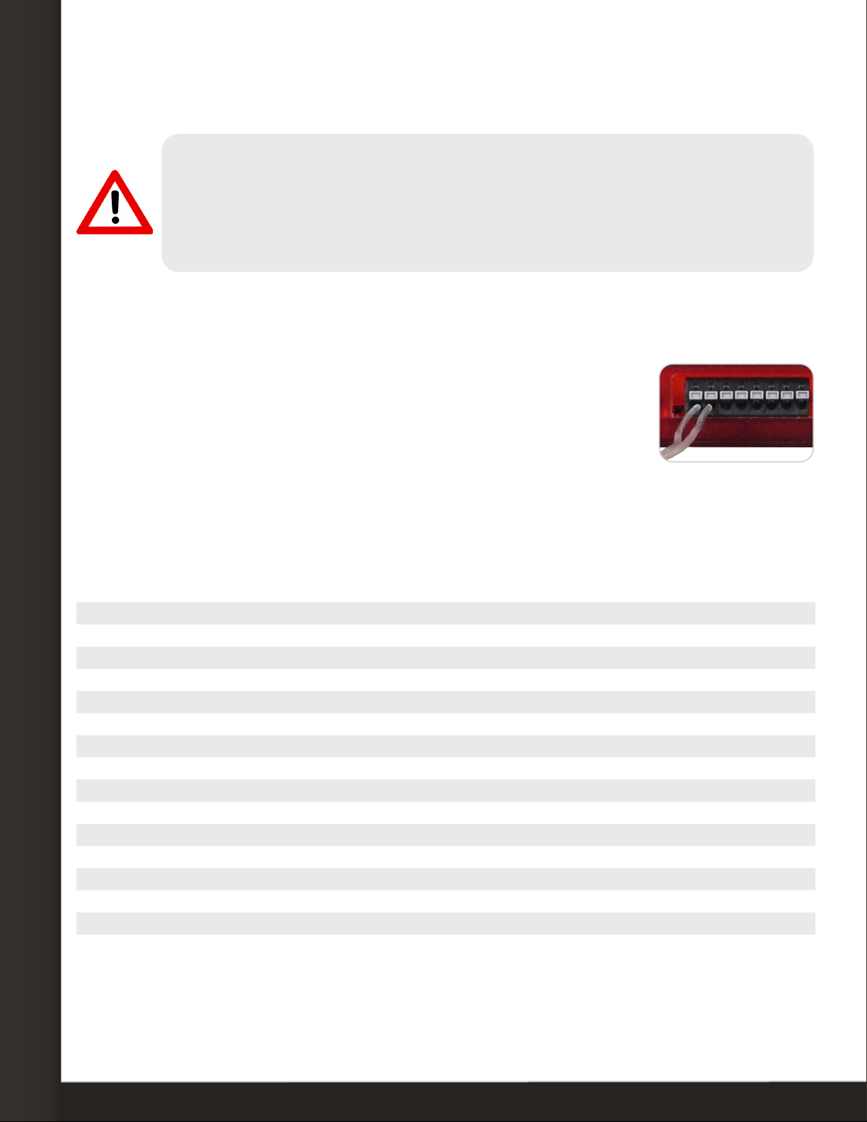
1. Separate and strip the free ends of the wire. Expose about ¼" of
wire.
2. Connect one end of the wire to an output port on the Relay
Switch. The port’s contacts are non-polarized, so you may insert
either side of the wire into either contact.
3. Connect the other end to the appropriate contacts on your electrical device.
4. Repeat this procedure for up to 3 more electrical devices.
Sensor Features & Specications
Environment Condition Monitored Turns on/o low-voltage electrical devices
Type Of Sensor Relay output
Power Supply Room Alert or Light Tower Adapter (LTA)
Sensor Cable Type
Relay output cable
Included No
Maximum Extendible Length Depends on application/type
Custom cable
Included Yes (built-in)
Length 3' 11"
Maximum Extendible Length 900'
Operating Temperature -40º F to 185º F (-40º C to 85º C)
Maximum Load On Relay Ports 0.3A at 125VAC; 1A at 24VDC
Compatible Products
Adapter Light Tower & Relay Adapter (LTA)
Main Units
Room Alert 32S and 12S (LTA required)
Room Alert 32E/W, 12E and 3E (LTA required)
Room Alert 4E (no LTA required)