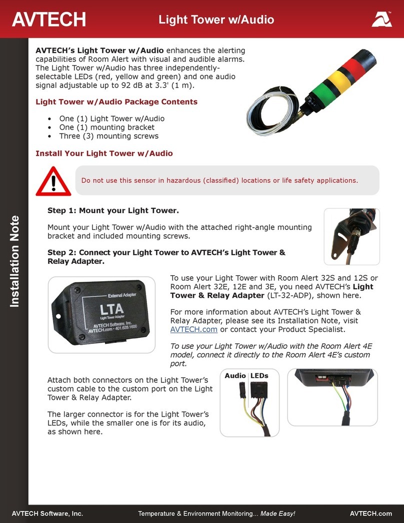
Avtech RoomAlert 32S User manual

Room Alert S Models (32S, 12S & 3S)
AVTECH Software, Inc. AVTECH.com
User’s Guide & Reference Manual

Copyright Information
© Copyright 1988-2023 AVTECH Software Inc.
All Rights Reserved. No part of this book may be used or reproduced for commercial benefit in any form or by any means, or
stored in a database or retrieval system, without prior written permission of AVTECH Software Inc., except in the case of brief
quotations embodied in articles and reviews. Making copies of any part of this book for any purpose other than your individual
use is a violation of United States copyright laws and international treaty provisions. For information or additional copies, contact
AVTECH Software Inc., as directed below. Published in the United States of America.
Warning and Disclaimer
This publication is shipped as is, without warranty of any kind, either express or implied. While every precaution has been taken
in the preparation of this publication, the publisher and authors assume no responsibility for errors or omissions. Neither is
any liability assumed for damages resulting from the use of the information or instructions contained herein. It is further stated
that the publisher and authors are not responsible for any damage or loss to your data or equipment that may result directly
or indirectly from your use of this publication and the related hardware & software. Nothing on any AVTECH website or in
documentation shall be construed as conferring any license under any of the AVTECH Software (AVTECH) or any third party’s
intellectual property rights, whether by estoppel, implication, or otherwise.
Trademark Acknowledgements
AlertScript, AVTECH, the AVTECH Logo, AVTECH Software, the AVTECH System Manager Character, AVTECH.com,
AVTECHSoftware.com, Environment Alarm, “Environment Monitoring Made Easy!”, EnvironmentMonitor.com, “IT Environment
Monitoring Made Easy!”, MUPS, Device Discovery, Device ManageR, “Protect Your Facility... Don’t Wait Until It’s Too Late!”, “Protect
Your IT Environment... Don’t Wait Until It’s Too Late!”, Room Alert, Room Alert Signal Tower, Signal Tower, RoomAlert.com,
RoomAlert.co.uk, RoomAlert.eu, TemPageR, TemPageR.com and “Temperature Monitoring Made Easy!”, WiSH, and WiSPR, are
trademarks or registered trademarks of AVTECH Software Inc. Any other trademarks, product or company names mentioned
herein are the property of their respective owners and used strictly for the purpose of identifying compatibility. AVTECH Software
Inc. cannot attest to the accuracy of any other organization’s ownership claim to a trademark and use of any trademark in this
publication should not be regarded as affecting the validity of any trademark or service mark.
Contact Us
Worldwide Headquarters
AVTECH Software, Inc.
16 Cutler Street, Cutler Mill
Warren, RI 02885-2761 USA
Visit us on the web at AVTECH.com
Log in to your account at RoomAlert.com
Sales
Need to expand your monitoring capacity? Visit our online store 24/7 at
https://AVTECH.com/Products/Environment_Monitors/
Want expert advice? Contact our Product Specialists Monday to Friday, 9 AM to 5 PM EST (excluding holidays).
Quote Request at https://AVTECH.com/quote/
Live Sales Chat at https://AVTECH.com/
888-220-6700 (In the USA & Canada, toll-free)
401-628-1600 (Outside the USA & Canada)
Technical Support
Questions about your product? Get answers 24/7 at our online Support Center.
Need more help? Contact our Technical Support Monday to Friday, 9 AM to 5 PM EST (excluding holidays).
Live Support Chat at https://AVTECH.com/support/
888-220-6700 (In the USA & Canada, toll-free)
401-628-1600 (Outside the USA & Canada)
AVT-230111

AVTECH Software, Inc. Page 3 AVTECH.com
Table of Contents
Room Alert S Model Hardware Options............................................................................. 4
Room Alert 32S...................................................................................................................... 4
Room Alert 12S...................................................................................................................... 5
Room Alert 3S........................................................................................................................ 5
Room Alert Hardware Features.......................................................................................... 6
How To Install Your Room Alert S Model........................................................................... 7
Connect Your Room Alert Hardware ................................................................................. 7
If Your Network Is Power Over Ethernet (PoE) Enabled ............................................ 7
If Your Network Is Not Power Over Ethernet (PoE) Enabled..................................... 7
Connect External Sensors And Other Compatible Components................................... 7
How To Use Your Room Alert S Model Web Interface ..................................................... 8
Status...................................................................................................................................... 8
Banner & Header ............................................................................................................ 9
Sensor Display Area...................................................................................................... 10
Settings................................................................................................................................. 12
Sensors ........................................................................................................................... 14
Alarms............................................................................................................................. 21
Network.......................................................................................................................... 25
Email ............................................................................................................................... 28
SNMP .............................................................................................................................. 30
Security........................................................................................................................... 33
Advanced........................................................................................................................ 34
For More Information ........................................................................................................ 38
Room Alert S Models (RA32S-DAP-RAS, RA12S-DAP-RAS & RA3S-ESO-BAS)

AVTECH Software, Inc. Page 4 AVTECH.com
Room Alert S Models (RA32S-DAP-RAS, RA12S-DAP-RAS & RA3S-ESO-BAS)
Room Alert S Model Hardware Options
Room Alert 32S
Front
Light Tower &
Relay Adapter
Ports
(2)
Alarm
LEDs
Digital
Sensor
Ports
(8)
9
Power
LED
2510 6
Back
Internal Sensors
• Temperature
• Humidity
• Power
• Battery Back-up
1
874311
Relay
Output
Ports
(2)
Analog
Input
Ports
(2)
Switch
Sensor
Ports
(16)
Reset
Button
Battery
Back-up
On / O
Button
Power
Port
Ethernet
Port
(PoE enabled)

AVTECH Software, Inc. Page 5 AVTECH.com
Room Alert S Models (RA32S-DAP-RAS, RA12S-DAP-RAS & RA3S-ESO-BAS)
Room Alert 12S
Front
5
Digital
Sensor
Ports
(3)
1
Power
Port
Back
Internal Sensors
• Temperature
7
Analog
Input
Port
4
Switch
Sensor
Ports
(4)
3
Reset
Button
8
Relay
Output
Port
Room Alert 3S
Front
2
(PoE enabled)
Ethernet
Port
1
Power
Port
Back
3
Reset
Button
4
Switch
Sensor
Port
5
Digital
Sensor
Port
2
(PoE enabled)
Ethernet
Port
Internal Sensors
• Temperature

AVTECH Software, Inc. Page 6 AVTECH.com
Room Alert S Models (RA32S-DAP-RAS, RA12S-DAP-RAS & RA3S-ESO-BAS)
Internal Temperature Sensor An internal digital sensor monitors ambient temperature
with a range of -40° to 185° F (-40° to 85° C).
Internal Humidity Sensor
Room Alert 32S
An internal digital sensor monitors relative humidity with a
range of 5% to 95% RH.
Internal Power Sensor
Room Alert 32S
An internal sensor monitors the power state (main power
or battery-back up power).
Internal Battery Back-up
Room Alert 32S
An internal battery back-up can power Room Alert 32S for
up to 15 minutes.
Power Port
A standard power port connects Room Alert to an
electrical outlet with any AVTECH 5V 1A Power Adapter.
Models are available for all countries.
Ethernet Port An RJ-45 port connects Room Alert to your network via an
RJ-45 Ethernet cable.
Reset Button A small push button resets Room Alert to factory default
settings. (Please push softly.)
Switch Sensor Port(s)
Dry contacts connect Room Alert to any AVTECH switch
sensor or dry contact on a device (e.g., HVAC, generator,
pump, fan, etc.) via standard speaker wire or low-voltage
2-wire cable.
Digital Port(s)
Standard RJ-11 jacks connects any AVTECH digital sensor
to Room Alert via a standard RJ-11 (straight through)
telephone cord.
Light Tower & Relay Adapter Port(s)
A standard RJ-11 jack connects a Light Tower & Relay
Adapter to Room Alert via a standard RJ11 (straight
through) telephone cord.
Analog Input Port(s)
Room Alert 32S &12S
Sets of contacts connect any low-voltage analog sensor to
your Room Alert via standard speaker wire.
Relay Output Port(s)
Room Alert 32S &12S
Sets of contacts connect any low-voltage device to your
Room Alert via standard speaker wire.
Power Status LED
Room Alert 32S
An LED indicates the power status of Room Alert 32S
(Green = Main or PoE, Red = Internal UPS power).
Alarm LEDs
Room Alert 32S
LEDs light red or green to indicate alarm or clear status of
Digital or Switch sensors (Green = Clear, Red = Alarm).
Battery Back-up On / O Button
Room Alert 32S
A push button turns the Room Alert’s internal battery
back-up on and o.
1
2
3
4
5
6
7
8
9
10
11
Room Alert Hardware Features

AVTECH Software, Inc. Page 7 AVTECH.com
Room Alert S Models (RA32S-DAP-RAS, RA12S-DAP-RAS & RA3S-ESO-BAS)
How To Install Your Room Alert S Model
Connect Your Room Alert Hardware
If Your Network Is Power Over Ethernet (PoE) Enabled
• Connect one end of a standard Ethernet cable to the
Room Alert’s Ethernet port.
• Connect the other end to a PoE-enabled network jack.
That’s it! Your Room Alert is now powered and discoverable
on your network.
If Your Network Is Not Power Over Ethernet (PoE) Enabled
A. Connect To Your Network First
• Connect one end of a standard Ethernet cable to the Room Alert Ethernet port.
• Connect the other end to a network jack.
B. Then Connect To A Power Source
• Plug one end of AVTECH’s 5V 1A Power Adapter into the Room Alert
power port.
• Plug the other end into a surge-protected power source.
Your Room Alert is now powered and discoverable on your network!
NOTE
Connect Included External Sensors And Other Compatible Components
Please install included external sensors and any other compatible components you may have purchased
according to their Installation Notes, available at AVTECH.com.
Use only AVTECH’s 5V 1A Power Adapter. Other voltages could damage the Room Alert
hardware and void your warranty. If you don’t have an AVTECH 5V 1A Power Adapter,
please visit our online store at AVTECH.com to acquire one. Models are available for all
countries.

AVTECH Software, Inc. Page 8 AVTECH.com
Room Alert S Models (RA32S-DAP-RAS, RA12S-DAP-RAS & RA3S-ESO-BAS)
How To Use Room Alert S Model Web Interface
You may congure your Room Alert through its built-in web interface. To access the interface, you may
either:
• Type the IP address of your Room Alert monitor directly into the address bar of your web
browser.
• Discover your Room Alert monitor with the Room Alert Discovery utility or Room Alert Link
software, and select its IP address displayed within the software.
• Select your Room Alert monitor in your RoomAlert.com account and click the Device Interface
button.
Your Room Alert’s web interface has 3 tabs:
• Status
• Settings
• Help
Status
To view your Room Alert’s current sensor status, select Status in the navigation bar to the left of your
screen.

AVTECH Software, Inc. Page 9 AVTECH.com
Room Alert S Models (RA32S-DAP-RAS, RA12S-DAP-RAS & RA3S-ESO-BAS)
Banner & Header
Banner
At the top of the page runs the Room Alert banner.
Header
Below the banner is the header, where you may view basic information about your device.
On the left side of the header, you may nd the following information:
• Device Name
• Model
• MAC Address
• Serial Number
• Firmware Version
• Local IP Address
• Power Status ( Room Alert 32S)
On the right side of the header, you may nd the following information under Account Status:
• The account your Room Alert monitor is registered to in RoomAlert.com.
• Your RoomAlert.com account level.
• Whether push to RoomAlert.com is enabled.
• Whether the Room Alert monitor is connected to your RoomAlert.com account.
• The time & date the Room Alert monitor last pushed sensor data to your
RoomAlert.com account.

AVTECH Software, Inc. Page 10 AVTECH.com
Room Alert S Models (RA32S-DAP-RAS, RA12S-DAP-RAS & RA3S-ESO-BAS)
Sensor Display Area
In the main viewing pane of the Status tab is the sensor display area. Here you may view your sensor data
and temporarily change Status page settings.
Temporary Status Page Settings
You may temporarily change the refresh interval of the Status page and default temperature scale here.
• To temporarily modify the refresh interval of the Status screen, which is 5 seconds by default,
you may enter a value in seconds in the Refresh this page every X seconds eld. Click outside the
eld to temporarily commit the change.
• To temporarily toggle the temperature scale between Fahrenheit (F) and Celsius (C), select
Fahrenheit or Celsius.
Tip
Alarm Status Icons
Status icons are displayed for sensors that have thresholds set:
Green circle with “” mark .............. Sensor is in a clear state.
Red circle with “X” mark ................... Sensor is in an alarm state.
No status icon.................................... Sensor has no thresholds set.
Refer to the Advanced section in this manual for instructions on setting the default
status page refresh rate and temperature scale for Room Alert.

AVTECH Software, Inc. Page 11 AVTECH.com
Room Alert S Models (RA32S-DAP-RAS, RA12S-DAP-RAS & RA3S-ESO-BAS)
High And Low Reading Icons
Arrows are displayed next to the highest and lowest readings on a sensor since the Room Alert last
rebooted:
Red upward arrow ............................ Highest reading since last reboot of Room Alert.
Blue downward arrow...................... Lowest reading since last reboot of Room Alert.
Navigating The Status Page
Your Room Alert displays your sensors in the following order:
• Digital Sensors
• Switch Sensors
• Light Towers and Relays
• Built-in Analog Sensors
To navigate to the dierent types of sensors in the Sensor Display Area, you may scroll down the page or
select the sensor category from the navigation bar to the left of your screen.
Note Sensors connected to analog input ports and light tower & relay ports do not appear
on the Status page until you enable them in the Settings screen. Refer to Settings in
this manual for instructions.

AVTECH Software, Inc. Page 12 AVTECH.com
Room Alert S Models (RA32S-DAP-RAS, RA12S-DAP-RAS & RA3S-ESO-BAS)
Settings
Accessing Settings
To access your Room Alert’s settings:
1. Select Settings in the navigation bar to the left of your screen.
2. Next, enter your credentials in the Username and Password elds.
• If you did not save custom credentials to your Room Alert already, enter these default
credentials:
○Username: admin
○Password: password
• Then select Click Here To Access Settings.
Navigating Settings
Settings has the following sub-tabs shown in the navigation bar to the left of your screen.
• Sensors
• Alarms
• Network
• Email
• SNMP
• Security
• Advanced
You may navigate to each of these sections by selecting the appropriate sub-tab. Settings opens by
default to the Sensor Settings page.
Saving Settings
To save a setting, click out of the eld you just modied and notice that a notication bar appears at the
top and bottom of the page.
This notication bar contains the following items:
• A list of Settings pages you have unsaved changes on.

AVTECH Software, Inc. Page 13 AVTECH.com
Room Alert S Models (RA32S-DAP-RAS, RA12S-DAP-RAS & RA3S-ESO-BAS)
• A Save Settings button.
• A Clear Changes button.
You may navigate among the Settings pages, making changes in dierent places, and then save the
changes all at once. When you are ready to save all the modications you’ve made, select the Save
Settings button. Your Room Alert will automatically reboot and commit your changes.
Before you save, if you decide you don’t want the changes you just entered, you may re-load
the page(s) without them by using the Clear Changes button. Settings will re-load without your
modications. The Room Alert does not reboot, and any already-saved settings remain.

AVTECH Software, Inc. Page 14 AVTECH.com
Room Alert S Models (RA32S-DAP-RAS, RA12S-DAP-RAS & RA3S-ESO-BAS)
Sensors
Navigate to Settings →Sensors to open the Sensor Settings screen.
You may congure alert thresholds for your Room Alert’s sensors in this screen. Your Room Alert sends
alerts based on these thresholds.
Note
Note
Digital Sensor Settings
You may congure alarm thresholds for the digital sensors—both internal and external—in this section.
For more information about AVTECH sensors and accessories, please visit the Sensors
and Accessories sections of AVTECH.com.
Notice the Use Alarm Prole drop-down menu next to each sensor. If you have an
AVTECH Light Tower, Relay Switch or built-in relays on your Room Alert, you may
congure Alarm Proles to toggle them on and o when alarms are detected. Please
refer to the Alarms section in this manual for further information.
The Room Alert 32S has an internal temperature sensor and an internal humidity
sensor. The Room Alert 12S and 3S have an internal temperature sensor.

AVTECH Software, Inc. Page 15 AVTECH.com
Room Alert S Models (RA32S-DAP-RAS, RA12S-DAP-RAS & RA3S-ESO-BAS)
In the example below, we will congure a Digital Temperature Sensor:
1. In Sensor Label, you may leave the default label, “Internal Sensor” (or “Ext Sensor 1,” etc.) or
rename it to something more descriptive, such as “Server Rm Temp.”
Tip
2. The Alarm On eld automatically lls in—in this case with “Temperature (F).”
Note
3. The High and Low elds are disabled by default.
• To enable a High or Low threshold, select the check box in that eld.
• You may then leave the default value or enter a custom temperature threshold.
• Your Room Alert will generate alerts based on these thresholds.
4. In Adjust, you may enter a value to adjust the temperature reading if it diers from a known value
at that location.
5. In Use Alarm Prole, which controls light towers and relays on your Room Alert, you may leave the
default, Prole 1, or choose another prole from the drop-down menu.
Note
6. Select Save Settings at the top or bottom of the page. Your Room Alert will automatically reboot
and commit your changes.
Tip
On Room Alert S models, sensor labels may be up to 30 characters and can include the
following: letters, numbers, spaces, and special characters.
Refer to the Advanced section in this manual for instructions on setting the default
temperature scale.
If you have an AVTECH Light Tower, Relay Switch or built-in relays on your Room Alert,
you may congure Alarm Proles to toggle them on and o when alarms are detected.
Please refer to the Alarms section in this manual for further information.
The options in the Sensor Alarm Conguration elds vary slightly depending on the type
of digital sensor.

AVTECH Software, Inc. Page 16 AVTECH.com
Room Alert S Models (RA32S-DAP-RAS, RA12S-DAP-RAS & RA3S-ESO-BAS)
Analog Sensor Settings
You may congure the 0-5 VDC analog sensor connected to your device’s built-in analog port(s) in these
elds.
In the example below, we are conguring AVTECH’s Current Loop 1.
1. First, enable the sensor by selecting Enabled in the set of elds to the right of the sensor
congurations. The built-in analog sensor will not appear in the Room Alert web interface, Room
Alert Manager, RoomAlert.com account or SNMP programs unless it is enabled.
2. In the set of elds toward the bottom of the sensor congurations, select Enabled to turn on the
Reference, Scale and Unit elds.
• In Reference, enter values from 5 to 0 that represent the High and Low points of your analog
sensor’s output signal range. In the case of the Current Loop 1, which outputs a signal of 0-5
VDC, we’ve left the default values.
• In Scale, enter the High and Low points of the scale you want the Reference reading to be
converted to. In our Current Loop example, we would like to convert 0-5 volts to 0-10 amps, so
we’ve replaced the default of 5 in High with 10 and left the default of 0 in Low.
• In Unit, enter a 1 to 3-character label for the unit type that your readings will be measured in.
If you are measuring amperage, as with the Current Loop, you might enter “A” or “Amp,” for
example. Note that this eld is merely a label and does not aect any of the calculations.
3. Return to the upper section of the sensor congurations to enter your sensor label and
thresholds:
• In Sensor Label, you may leave the default, “Analog 1” or choose something more descriptive,
such as “Current Loop 1” or “Cryogenic Temp.”
Tip On Room Alert S models, sensor labels may be up to 30 characters and can include the
following: letters, numbers, spaces, and special characters.

AVTECH Software, Inc. Page 17 AVTECH.com
Room Alert S Models (RA32S-DAP-RAS, RA12S-DAP-RAS & RA3S-ESO-BAS)
4. The High and Low elds are disabled by default.
• To enable a High or Low threshold, select the check box in that eld.
• You may then leave the default value or enter values that fall within the Scale range from the
previous step. In our example, we entered a conversion scale of 0 to 10 (amps) in the previous
step for the Current Loop, and we’ve chosen to generate alarms at the high and low thresholds
of 6 and 2 (amps).
Tip
• The Adjust eld is not available if custom scale is enabled. When custom scale is disabled, you
may enter a value to adjust the reading if it diers from a known value.
Tip
5. In Use Alarm Prole, which controls light towers and relays on your Room Alert, you may leave the
default, Prole 1, or choose another Alarm Prole from the drop-down menu.
Note
6. Select Save Settings at the top or bottom of the page. Your Room Alert will automatically reboot
and commit your changes.
Switch Sensor Settings
You may congure the alert state for the external switch sensors in the Switch Sensor Settings elds.
Shown below are the default settings.
With the custom scale enabled, you may enter positive and negative whole numbers
in High and Low that fall within the Scale range; with the custom scale disabled, you may
enter decimal numbers in the range of +/-5.0 (for 0-5 VDC).
With the custom scale disabled, you may enter decimal numbers in the range of +/-5.0.
If you have an AVTECH Light Tower, Relay Switch or built-in relays on your Room Alert,
you may congure Alarm Proles to toggle them on and o when alarms are detected.
Please refer to the Alarms section in this manual for further information.

AVTECH Software, Inc. Page 18 AVTECH.com
Room Alert S Models (RA32S-DAP-RAS, RA12S-DAP-RAS & RA3S-ESO-BAS)
Your Room Alert monitors your switch sensors for an “Open” or “Closed” circuit state. Room Alert defaults
to alarming on “Closed,” as you can see above; you may, however, need to change that depending on
your sensor. AVTECH’s Motion Sensor, for example, is “Open” when it detects movement and “Closed”
when it doesn’t; in that case, you’d likely want to congure the sensor to alarm on “Open” or when motion
is detected.
The Alarm And Clear State Of Your Switch Sensor
To determine the alarm and clear state of your sensor, you may either refer to its Installation Note or see
for yourself by physically connecting your sensor to your Room Alert and then observing what happens to
its circuit state in the Status page.
After you connect your sensor and before you congure it in the Settings page, follow these steps:
1. Select the Status tab in the navigation bar to the left of your screen.
2. Scroll down to the Switch Sensors and look at the circuit state of the channel you connected your
sensor to. If you connected your sensor to the rst switch sensor port on Room Alert, look at
Channel 1; if you connected it to the second, look at Channel 2, etc.
3. Notice the circuit state of Switch 1. It should show the normal state, which in this case is “Closed.”
(Ignore the red color coding for now. We haven’t congured the sensor yet, so it’s still set at the
default: alarm on closed.)
4. Now put the sensor into an alarm state. To put a Motion Sensor into an alarm state, for example,
wave your hand in front of it.
5. Look at the circuit state at the same time. You should see it switch to the
opposite of normal. In this example, if normal is “Closed,” you see the alarm
state as “Open.” (Again, ignore the green color coding for now.)
Now that you’ve checked what “Open” and “Closed” mean on your switch sensor, navigate to Settings
→Sensors to congure your options in Switch Sensor Settings:

AVTECH Software, Inc. Page 19 AVTECH.com
Room Alert S Models (RA32S-DAP-RAS, RA12S-DAP-RAS & RA3S-ESO-BAS)
1. In Sensor Label, you may leave the default, “Switch Sensor 1” (2, 3 or 4, etc.) or enter something
more descriptive, such as “Ext Motion” or “Main Entry.”
Tip
2. In Alarm On, select the alarm state (Open or Closed). In our example, the alarm state is Open.
3. In Alarm Prole, which controls light towers and relays on your Room Alert, you may leave the
default, Prole 1, or choose another Alarm Prole from the drop-down menu.
Note
4. Select Save Settings at the top or bottom of the page. Your Room Alert will automatically reboot
and commit your changes.
Tip
Internal Power Sensor Alarm Conguration ( Room Alert 32S)
You may congure the power sensor that is built in to the Room Alert 32S here. This internal power
sensor triggers on loss of main power and can send a notication while the battery back-up keeps the
Room Alert monitor powered for a short time.
1. In Internal Power Sensor Label, you may leave the default “Power Sensor” or enter something more
descriptive, such as “RA32S Power.”
Tip
2. In Alarm On Power Loss, you may leave the checkbox lled in if you wish to receive an alert when
your Room Alert 32S loses its main power source. Otherwise, you may uncheck it.
On Room Alert S models, sensor labels may be up to 30 characters and can include the
following: letters, numbers, spaces, and special characters.
If you have an AVTECH Light Tower, Relay Switch or built-in relays on your Room Alert,
you may congure Alarm Proles to toggle them on and o when alarms are detected.
Please refer to the Alarms section in this manual for further information.
For any of the switch sensor sets you leave unused on your Room Alert, choose
Disabled from the Alarm On drop-down menu to avoid confusion or false alerts.
Room Alert 32S sensor labels may be up to 30 characters and can include the following:
letters, numbers, spaces, and special characters.

AVTECH Software, Inc. Page 20 AVTECH.com
Room Alert S Models (RA32S-DAP-RAS, RA12S-DAP-RAS & RA3S-ESO-BAS)
3. In Alarm Prole, which controls light towers and relays on your Room Alert, you may leave the
default, Prole 1, or choose another Alarm Prole from the drop-down menu.
Note
4. Select Save Settings at the top or bottom of the page. Your Room Alert will automatically reboot
and commit your changes.
If you have an AVTECH Light Tower, Relay Switch or built-in relays on your Room Alert,
you may congure Alarm Proles to toggle them on and o when alarms are detected.
Please refer to the Alarms section in this manual for further information.
This manual suits for next models
5
Table of contents
Other Avtech Safety Equipment manuals