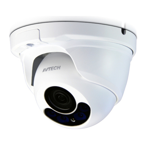
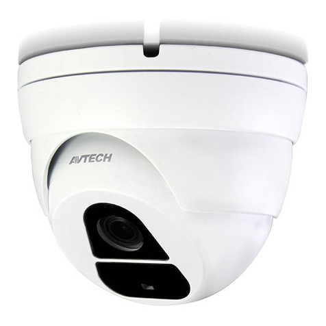
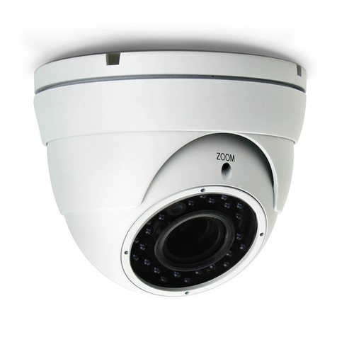
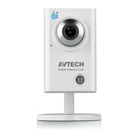
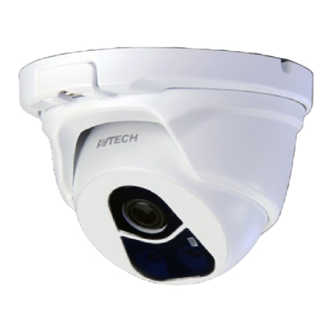
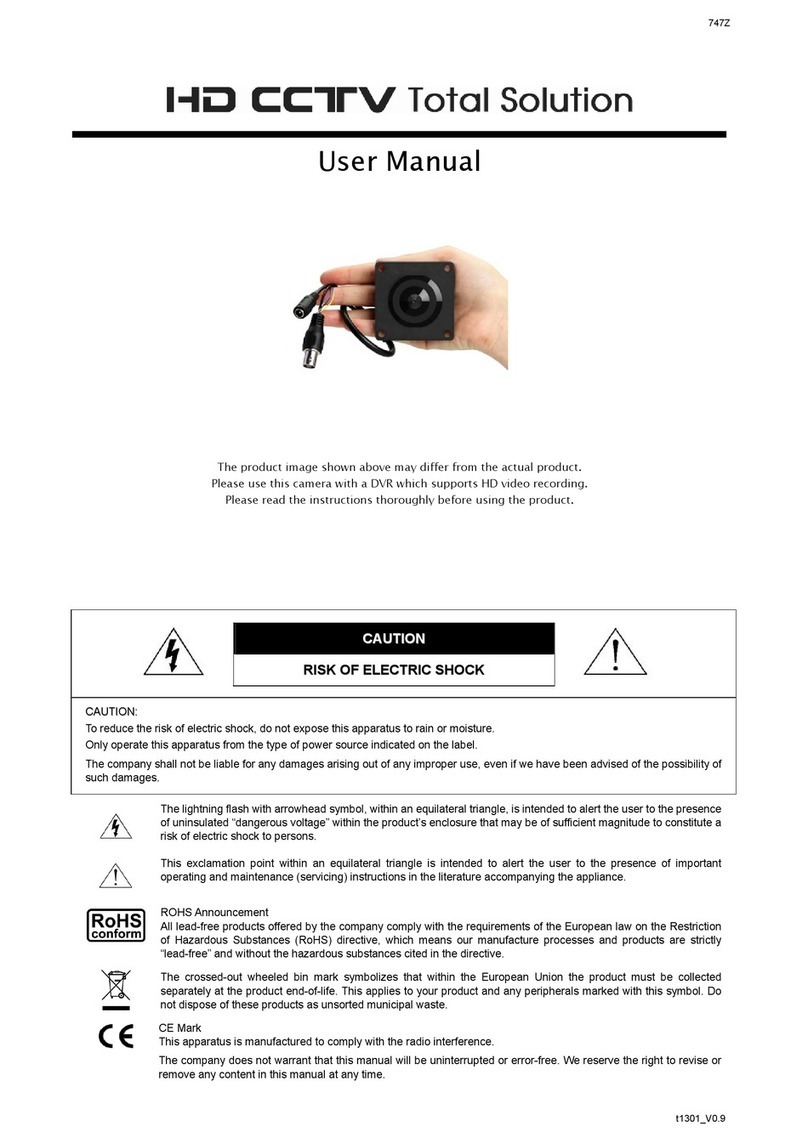
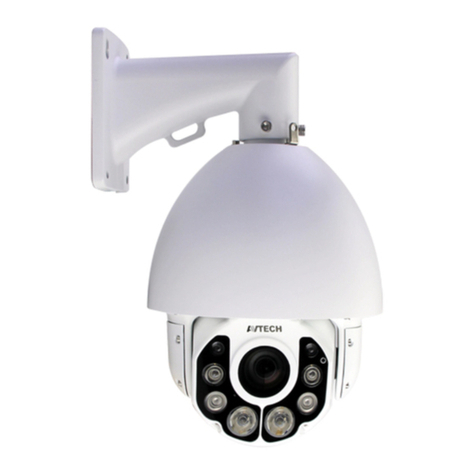
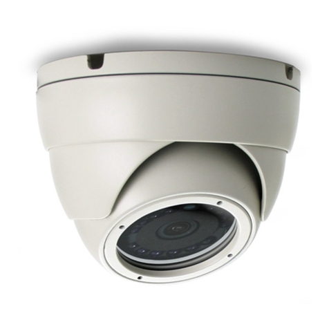
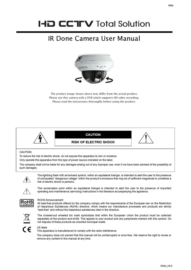
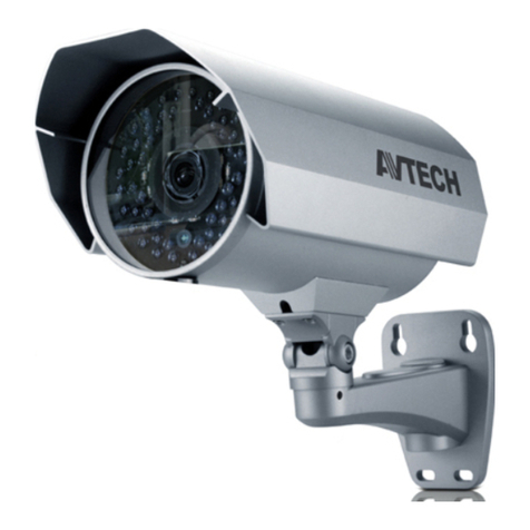
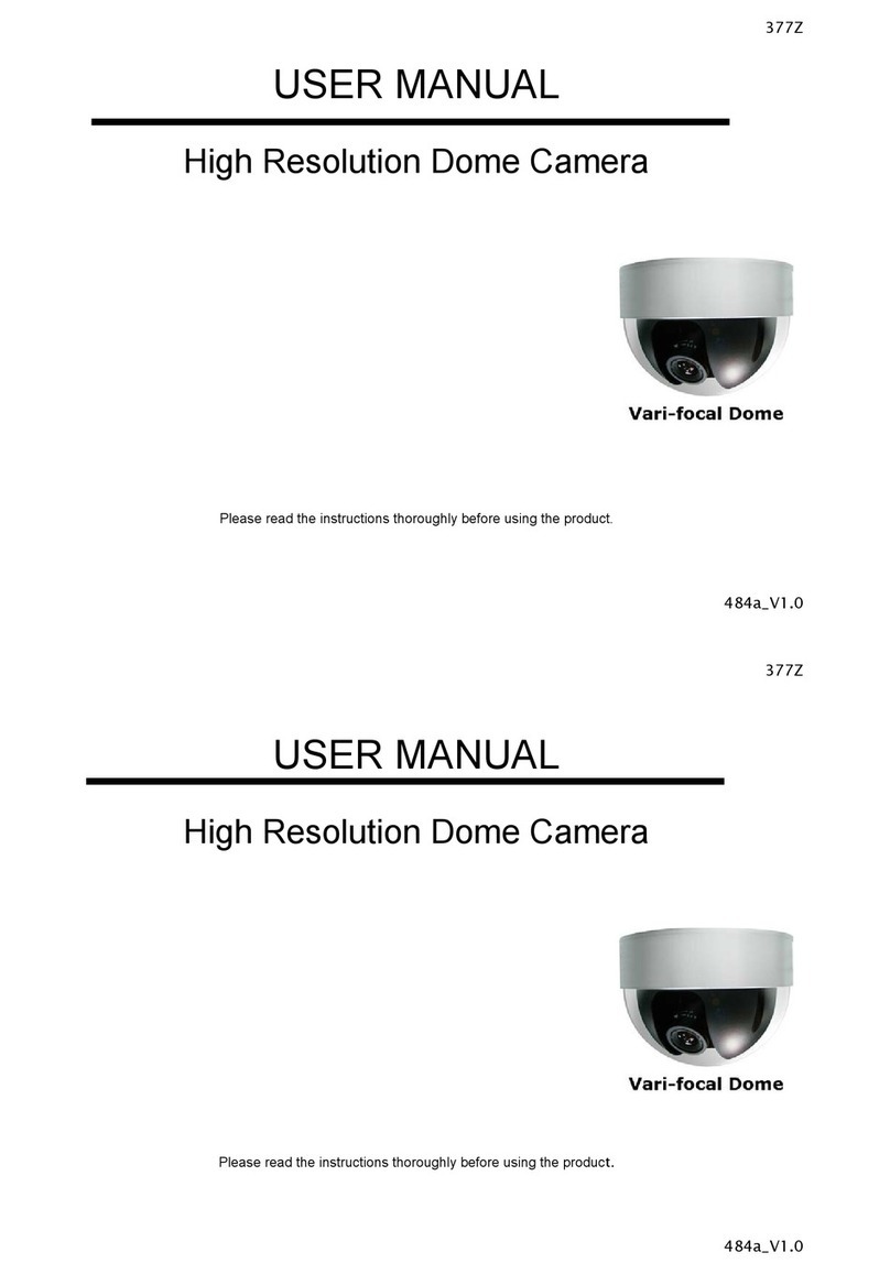
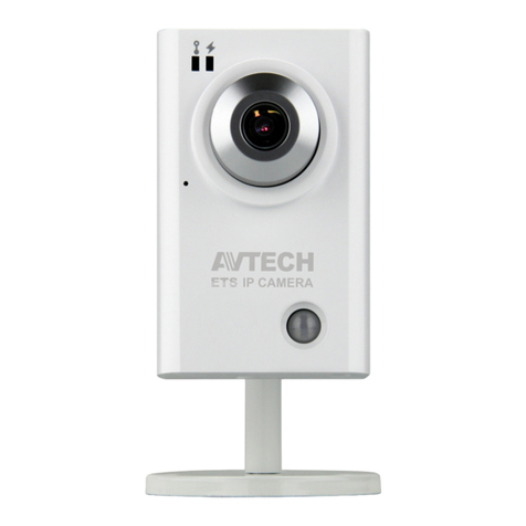
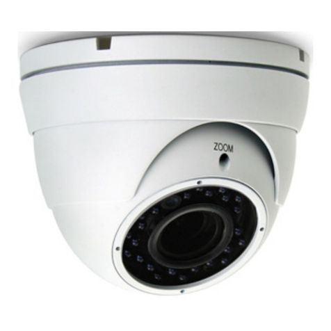
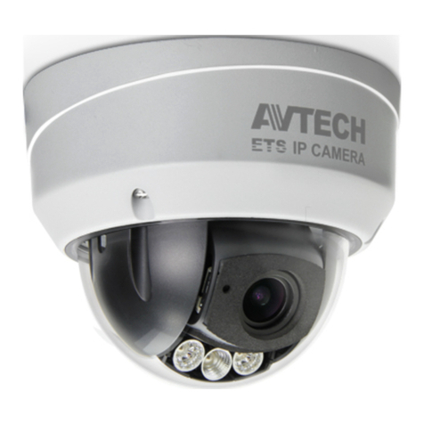
Avtech AVM332 User manual

621Z
m532_n332_320_320L_420_quick_V1.0
Package Content Cable Overview
QUICK GUIDE
Please read instructions thoroughly before operation and retain it for future
reference. Online manual download:
www.surveillance-download.com/user/m521.swf
Before starting to set up your camera, please make sure items below in your box:
Standard package:
Type 1 or Type 2
Camera Quick Guide CD
Optional accessories (For Type 1 only):
Screws & Wall Plugs x 3 Wrench
Below is an overview of various cables that can be used with the camera. Besides,
it is followed by a table, which offers simple descriptions of cable connection.
Power cable
RJ45 network cable
RESET
GND**
Alarm-out**
Alarm-in**
GND
Line-in (blue)**
Line-out (green)**
Cable Description
Power cable DC12V power supply.
RJ45 network cable* Connect it to a RJ45 cable.
GND Ground wire
Alarm-in** Reserved for external alarm device connection
Alarm-out** Reserved for external alarm device connection
RESET Remove the insulating coating of wire, and twist it with a ground
wire together to reset default camera
Line-in* Colored as blue, used to connect to a microphone for audio input.
Line-out* Colored as green, used to connect to a speaker for audio output.
* For PoE (IEEE802.3af) installation, make sure your network cable has the maximum cable
resistance of 20Ω, such as CAT.5e or CAT.6 cables, to conform to the standard of IEEE802.3af.
** For Type 1 only
Installation
Type 1 Type 2
Step1: Remove the camera base as shown in Figure 1, and disassemble the camera to four parts as shown in Figure 2.
Rotate anti-clockwise Remove
Camera lens Part 1 Part 2Base
Figure 1 Figure 2
Step2: Locate where you want to install this camera (wall or ceiling), and drill holes on the wall or ceiling for securing
the bracket and routing the cables (if necessary).
Step3: Attach the bracket to the wall (or ceiling), and make sure the cables are routed and arranged properly in the
bracket, as shown in Figure 3.
Step4: Secure the bracket to the wall (or ceiling), as shown in Figure 4.
W
here to look
Cable routing
Attach to wall (or ceiling)
Step 1: Uncover the dome camera by loosening the screws on the housing with the supplied wrench.
Step 2: Locate the three holes as illustrated in the right picture. They are where the three supplied screws belong.
Step 3: Mark the locations of the three screw holes on the ceiling or the wall, and drill a hole for each on the
ceiling or the wall.
Step 4: Screw the camera in place.
Step 5: Power up your camera.
Step 6: Check the viewing angle on the PC.
Step 7: Adjust the position and the viewing angle of the camera, if necessary.
Step 8: Replace the dome cover and have the three screws on it tightened.
Note: For clear images, please clear of fingerprints the inner part of the dome cover against the lens.
Figure 3 Figure 4
Installation (Continued) Focus Adjustment (For Type 1 only) Insert MicroSD Card (For Type 1 only)
Type 2
Step5: Slightly adjust the camera lens to where it’s supposed to
face, and replace Part 1 and Part 2 back, as shown in
Figure 5 and Figure 6.
Step6: Hold the camera lens and Part 1, and rotate only Part 2
clockwise, as shown in Figure 6.
Figure 5
Part 1
Figure 6
Hold camera & Part 1, and
rotate only Part 2 clockwise
Part 2
Step7: Power on your camera, and check the viewing angle on
the PC.
Step8: Adjust the position and the viewing angle of the camera, if
necessary.
If you need to adjust the focus, the picture below shows you how:
for adjusting focal length
for adjusting focus
Lens
Note: Remove the cover to focus the camera.
The data originally saved in the micro SD card (if any) will be removed
after inserting it to the camera.
The camera doesn’t support hot-swapping. Please insert or remove the
micro SD card with power disconnected.
Please follow the directions in the below graphic to insert Micro SD card
properly:
Note: It’s recommended to use a pair of tweezers for inserting / removing
Micro SD card.
Camera Configuration
For advanced configuration of your camera, please be sure you have
connected your camera to NVR as shown in “HD System
Connection”.
Note: It’s recommended to connect the camera to the same brand’s NVR to get
the best performance. To use the camera individually, please refer to the
camera’s operation guide supplied in the CD to know how to configure this
camera solely.
Step1: Connect PC to the HUB connected to your camera(s) with RJ45 network cable.
Step2: Search available devices with “IPScan.exe”; to download “IPScan.exe”, please browse the supplied CD, or visit
www.surveillance-download.com/user/IPscan.zip
Step3: After searching, set your PC in the same network segment as the specific camera you want to access, such as “192.168.30.xxx” (xxx could be 0~255)
in our example
Step4: Note down the IP address and port number of the camera you want to access, such as “192.168.30.1” and “88” in our example.
Step5: Open Internet Explorer on the PC, and enter the IP address and port number in the URL column to access the camera. The format is
http://ipaddress:portnum, such as http://192.168.30.1:88 in our example.

583Z
PACKAGE CONTENTS Camera Overview
Type 1 Type 2
QUICK GUIDE
For more product details, please visit
www.surveillance-download.com/user/m521.swf
Before starting to set up your camera, please make sure items below are in your
box:
Standard package:
or
Camera Quick Guide
Optional accessories:
Screws & Wall Plugs Wrench
Side View(depending on the model you use )
A
B
C
INSTALLATION
Type 1 Type 2
Step 1: Separate the dome cover from
the camera.
Step 2: Make sure the screw holes on the
plate are aligned with the holes
on the camera base. If not,
slightly loosen the two screws on
the plate and rotate it.
Step 3: Mark the locations of the two screw holes on the ceiling or wall, and drill a hole for each on the ceiling or wall. The distance between
your camera and the location you want to monitor should be 3 ~ 4 meters.
Step 4: Fix the camera to the ceiling or wall with the supplied screws.
Step 5: Connect your camera to power.
Step 6: Pan, tilt and rotate the lens itself to adjust the position and viewing angle of the camera, and fasten the two screws on the plate to fix.
Note: You don’t need to manually pan the type with motorized pan.
Step 7: Replace the dome cover back to the camera.
Note: Please wipe the inner part of the dome cover against the lens for clear images.
Step 1: Separate the dome cover from the camera.
Squeeze two sides of the dome cover as located and indicated below, and
move it upward to remove.
Step 2: Place the camera to where you want to install, on the ceiling or wall, and
mark the points for screws.
Step 3: (Optional) When the cable is arranged to walk along the wall, find and cut
as indicated below to let the cable out.
Step 4: Fix the camera to the ceiling or wall with the supplied screws.
Step 5: Connect your camera to power.
m521a_504a_311_511_328c_428c_328d_428d quick_V1.2
(TURN BACK TO CONTINUE)

INSTALLATION (Continued) Insert MicroSD Card (For selected models)
Type 2 (Continued) The data originally saved in the microSD card (if any) will be removed after inserting it to the camera.
The camera doesn’t support hot-swapping. Please insert or remove the microSD card with power disconnected.
Please follow the directions in the below graphic to insert microSD card properly:
Type 1 Type 2 Type 3
Step 6: Pan, tilt and rotate the lens to adjust the
position and viewing angle.
To rotate the lens, it’s recommended to
use the supplied wrench by inserting it
to any of the three holes on the lens.
Note: The rotation angle of the lens is not 360°.
When rotating the lens, do not force
the lens to rotate when you feel
resistance. Also, please leave the focal
length the way it is. The default is
already the optimum.
Step 7: Replace the dome cover back.
Note: Please wipe the inner part of the dome
cover against the lens for clear images.
Step 8: Fasten the cover screws as indicated
below.
CAMERA CONFIGURATION
For advanced configuration of your camera, please be sure you have connected your camera to
NVR as shown below:
Step 1: Connect PC to the HUB connected to your camera(s) with RJ45 network cable.
Step 2: Search available devices with “IPScan.exe”; to download “IPScan.exe”, please visit www.surveillance-download.com/user/IPscan.zip
Step 3:After searching, set your PC in the same network segment as the specific camera you want to access, such as “192.168.30.xxx” (xxx could be 0~255) in our
example
Step 4: Note down the IP address and port number of the camera you want to access, such as “192.168.30.1” and “88” in our example.
Step 5: Open Internet Explorer on the PC, and enter the IP address and port number in the URLcolumn to access the camera. The format is
http://ipaddress:portnum, such as http://192.168.30.1:88 in our example.

651Z
m542a_m542b_542f_quick_V1.3
Package Contents Installation
QUICK GUIDE
For more product details, please visit
www.surveillance-download.com/user/m521.swf
Before starting to set up your camera, please make sure items below are in your box:
Standard package:
Camera Quick Guide
Optional accessories:
Screws, Wall
Plugs, Rubber
Rings (×3)
Wrench Desiccants
(×2) Waterproof accessory kit
Step 1: Uncover the dome camera by loosening the three screws on the housing with the
supplied wrench.
Note: The three screws aren’t designed to be removed from the housing.
Step 2: Attach the supplied installation sticker to your desired installation location.
Step 3: Locate the three deepest holes on the base. (See Pic 1.) They are where the three
supplied screws belong.
On the sticker, make holes where the three screws and the cables are supposed to
penetrate. However, if the cables won't go through the surface, you don’t need to
make the hole for them in advance. Next, align the camera with the sticker, putting
the three screws through the holes, as well as the cables—if necessary. Then,
tighten the screws.
Pic 1
Installation (Continued)
Step 4: The lens can be adjusted in three ways:
a. Take turn to pan the camera. b. Tilt the lens after loosening the two plastic
screws on either side of the lens.
c. Remove the protective case by loosening the two
screws on it before rotating the lens from behind.
Pan Tilt Rotate
Step 5: Be sure to replace the original desiccant(s) with the new ones. Use
provided double-sided tape to stick the desiccants in place as
illustrated below. Keep them inward enough for the housing to close
nicely. The new desiccants must not be exposed to air for over 30
seconds.
Note: Both the two new desiccants are to be put in the camera to remove
excessive humidity and ensure the camera works well.
Step 6: Then, clear the lens of fingerprints and replace the housing before
tightening the screws on it.
Note: To prevent the fuzzy image due to the IR reflection, please keep the
transparent cover clear.
Step 7: Power up the camera.
(TURN BACK TO CONTINUE)

Waterproof Accessories Installation
(Selected Model Only)
Preview the Viewing Angle with a BNC Monitor
(Selected Model Only)
Step 1: Pass the network cable without connector through the
plastic tube cover as the right illustration.
Step 2: Put the waterproof seal into the plastic tube.
Step 3: Pass the network cable through the plastic tube and
screw it tightly.
Step 4: Install a connector to the network cable.
Step 5: Put the O-Ring on the plastic tube as the left
illustration and connect the network cable with plastic
tube to the RJ45 waterproof connector of camera,
Step 6: Screw them tightly to prevent water seepage.
Focusing the Camera
If you need to adjust the focus, the picture shows you how to adjust.
TypeA TypeB
F
TW
Nfor adjusting focal length
for adjusting focus
lens
This camera support composite output for you to
preview the viewing angle if it’s correct or not
while installing camera. You need to open the
plate to find the receptacle housing of RCY
connector located next to the micro SD card
slot as the right illustration.
Please follow the specifications as below to
purchase the suitable plug.
Specification of contact Specification of housing
0.64
15.8
1.7 2
1.7 1.7
11
1.8 2
1.1
9.5
2.5
2.9
6.7
2.5
3.2
5.3
6.3
13
4.3
19
Receptacle housing (for pin contact) Plug (for socket contact)
Overview of optional plug cable
Connect to a RCA cable
Camera Configuration Inserting MicroSD Card
For advanced configuration of your camera, please be sure you have
connected your camera to NVR as shown below:
Step1: Connect PC to the HUB connected to your camera(s) with RJ45 network cable.
Step2: Search available devices with “IPScan.exe”; to download “IPScan.exe”, please visit
www.surveillance-download.com/user/IPscan.zip
Step3: After searching, set your PC in the same network segment as the specific camera
you want to access, such as “192.168.30.xxx” (xxx could be 0~255) in our example
Step4: Note down the IP address and port number of the camera you want to access, such
as “192.168.30.1” and “88” in our example.
Step5: Open Internet Explorer on the PC, and enter the IP address and port number in
the URL column to access the camera. The format is http://ipaddress:portnum,
such as http://192.168.30.1:88 in our example.
The data originally saved in the microSD card (if any) will be removed after
inserting it to the camera.
The camera doesn’t support hot-swapping. Please insert or remove the microSD
card with power disconnected.
Please follow the directions in the below graphic to insert MicroSD card properly:
Receptacle housing
Plug (Optional)

593Z
es_m521a_504a_311_511_328c_428c_328d_428d quick_V1.2
CONTENIDO DEL PAQUETE Vista de Cámara
Tipo 1 Tipo 2
Guía Rápida
Para ver más detalles, visite,
www.surveillance-download.com/user/m521.swf
Antes de comenzar a configurar su cámara, asegúrese de
que la caja contenga los siguientes elementos:
Contenido:
o
Cámara Guía Rápida
Accesorios Opcionales:
Tornillos y Taquetes Llave
ss
Vista de lado (dependiendo del modelo que use )
A
B
C
INSTALACION
Tipo 1 Tipo 2
Paso 1: Separe la cubierta de la cámara.
Paso 2: Asegúrese de que los orificios de
los tornillos en la placa estén
alineados con los orificios de la
base de la cámara. Si no es así,
afloje ligeramente los dos
tornillos de la placa y gírelo.
Paso 3: Marque las ubicaciones de los dos orificios de los tornillos en el techo o en la pared, y taladre un agujero para cada uno en el techo
o en la pared. La distancia entre la cámara y la ubicación que desea controlar debe ser de 3 ó 4 metros.
Paso 4: Fije su cámara al techo o a la pared con los tornillos que se incluyen.
Paso 5: Conecte su cámara a la energía.
Paso 6: Ajuste, incline y gire el lente para ajustar la posición y el ángulo de visión de la cámara, y fije los dos tornillos de la placa.
Nota: Usted no necesita hacerlo manualmente en la versión motorizada.
Paso 7: Vuelva a colocar la cubierta de la cámara.
Nota: Por favor, limpie la parte interior de la cubierta de la cúpula para obtener imágenes claras.
Paso 1: Separe la cubierta de la cámara.
Apriete los dos lados de la cubierta del domo que se encuentra y se indica a
continuación, y jale hacia arriba para extraerlo.
Paso 2: Coloque la cámara en donde la desea instalar en el techo o en la pared, y
marque los puntos para los tornillos.
Paso 3: (OpcionalCuando el cable sale de la cámara lo largo de la pared, guíe el
cable por la ranura , como se indica a continuación.
Paso 4: Fije su cámara al techo o a la pared con los tornillos que se incluyen.
Paso 5: Conecte su cámara a la energía.
(CONTINUA AL REVERSO)

INSTALACION (Continuación) Inserte la tarjeta MicroSD (De los modelos compatibles)
Tipo 2 (Continuación) Los datos originalmente almacenados en la tarjeta microSD (si los hay) se eliminarán después de insertarla en la cámara.
La cámara no admite el intercambio en caliente. Por favor, insertar o extraer la tarjeta microSD con la energía desconectada.
Por favor, siga las instrucciones en el siguiente gráfico para insertar la tarjeta microSD correctamente:
Type 1 Type 2 Type 3
Paso 6: Puede mover Horizontalmente, inclinar y girar el
lente para ajustar la posición y el ángulo de visión
adecuado.
Para girar la lente, se recomienda utilizar la llave
suministrada mediante la inserción a cualquiera de
los tres agujeros del lente.
Nota: El ángulo de rotación del lente no es 360 °. Al
girar el lente, no lo forcé, gire cuando note
resistencia. Además, por favor no mueva la
longitud focal. El valor predeterminado es ya la
visión óptima.
Paso 7: Vuelva a colocar la cubierta de la cámara.
Nota: Por favor, limpie la parte interior de la cubierta de la
cúpula para obtener imágenes claras.
Paso 8: Apriete los tornillos de la tapa como se indica a
continuación.
CONFIGURACION DE LA CAMARA.
Para la configuración avanzada de la cámara, asegúrese de que ha conectado la cámara al
NVR como se muestra a continuación:
Paso 1: Conecte su PC al switch conectado a su cámara (s) con el cable de red RJ45.
Paso 2: Buscar en los dispositivos disponibles con "IPScan.exe", para descargar "IPScan.exe", por favor visite www.surveillance-download.com/user/IPscan.zip
Paso 3: Después de buscar, configurar su PC en el mismo segmento de red que la cámara específica que desea acceder, por ejemplo, "192.168.30.xxx" (xxx puede
ser de 0 a 255) en nuestro ejemplo
Paso 4: Anote la dirección Ip y el número de puerto de la cámara que desee tener acceso, como “192.168.30.1” y “88” en nuestro ejemplo.
Paso 5: Abra Internet Explorer en su PC, y escriba la dirección IP y número de puerto en la columna de la dirección URL para acceder a la cámara. El formato es
http://ipaddress:portnum, tales como http://192.168.30.1:88 en nuestro ejemplo.

601Z
包裝明細 監視器外觀
第一類 第二類
快速使用指南
欲了解更多產品資訊,請上
www.surveillance-download.com/user/m521.swf
安裝監視器前,請先檢查盒內是否有下列物件。
標準配備:
或
攝影機 快速使用指南
選配:
螺絲 & 壁虎 扳手
側邊 (視型號而定)
A
B
C
安裝
第一類 第二類
1. 旋鬆螺絲,拿掉上蓋。
2. 把轉盤上的螺絲孔跟底座的
螺絲孔對齊,如果轉盤不易
旋轉,請先旋鬆轉盤上的兩
顆螺絲再旋轉。
3. 在天花板或是牆壁上標示底座螺絲孔的位置,然後鑽洞。攝影機距離監控的對象應該要三到四公尺遠。
4. 鎖上附贈的螺絲,把攝影機固定好。.
5. 攝影機上電。
6. 藉由旋轉轉盤、,調整鏡頭高低、旋轉鏡頭來調整攝影機的視角,接著,再把轉盤上那兩顆螺絲旋緊。
注意: 某些機種的轉盤會自動旋轉,這時就不必手動調整。
7. 蓋上外罩。
注意: 請先把鏡頭前的外罩內側擦拭乾淨,以免影響畫質。
1. 旋鬆螺絲,拿掉上蓋。如圖,按住上蓋的兩側,往上提起,
就能把外罩拿掉。
2. 把攝影機放在欲安裝的地方(天花板或是牆上),標示螺絲的
孔位。
3. 如果要沿著牆壁布線,請依照右下圖在特定處剪個缺口,好
讓電線伸展。
4. 鎖上附贈的螺絲,把攝影機固定好。
5. 攝影機上電。
(請翻到背面)中文_m521a_504a_311_511_328c_428c_328d_428d quick_V0.9

安裝(接上頁)插入 Micro SD 記憶卡
第二類 (接上頁)將micro SD 記憶卡插入攝影機後,原本儲存在內的資料會自動被清除。
攝影機並不支援熱插拔。在插入 micro SD 記憶卡前,請先中斷攝影機電源。
請依下圖指示插入 micro SD 記憶卡:
第一類 第二類 第三類
6. 藉由旋轉轉盤、,調整鏡頭高低、
旋轉鏡頭來調整攝影機的視角
若要旋轉鏡頭,請拿附贈的扳手
插進鏡頭旁其中一個孔來調整。
注意: 鏡頭旋轉角度並非 360°,若旋
轉時遇到阻力,請勿繼續施力,
此外,焦距也請不要隨意調整,
因為預設值已是最佳狀態。
7. 蓋上外罩
注意: 請先把鏡頭前的外罩內側擦拭
乾淨,以免影響畫質。
8. 照圖示把外照上的螺絲鎖緊。
攝影機設定
如需設定攝影機進階功能,請確認攝影機已連到同品牌的 NVR,例如下
圖。
DC12V INAUDIO
OUT
MOUSEUSBWAN
INTERNET
LAN
SWITCH
HDMIeSATA
LAN
SWITCH
NVR
RJ45 網路線
HUB
網路線
(一台攝影機一條網路線)
步驟 1:使用 RJ45 網路線,將您的電腦接到攝影機連接的同一台 HUB。
步驟 2:在電腦使用IPScan.exe搜尋可用裝置;若要安裝IPScan.exe,請至隨附光碟取得,或者至
www.surveillance-download.com/user/IPscan.zip下載。
步驟 3:搜尋完後,將電腦的網域設成和攝影機相同的網域。以下圖為例,電腦則需設成 192.168.30.xxx” (xxx 介於 0~255)。
步驟 4:記下您要登入的攝影機 IP 位址和埠號,例如上圖的 192.168.30.1 和88。
步驟 5:在電腦開啟 Internet Explorer,然後在 URL 欄輸入攝影機的 IP 位址和埠號,格式為 http://ip 位址:埠號。
以上圖為例,則需輸入 http://192.168.30.1:88。

578Z
fr_m521a_311_quick_V1.1
CONTENU GENERALITE
Type 1 Type 2
Installation Rapide
Veuillez lire les instructions attentivement avant
toute utilisation. Conservez précieusement cette
notice pour une consultation future.
Le manuel d’utilisateur complet est téléchargeable sur
le site www.cpcamcctv.fr ou
www.surveillance-download.com/user/m521.swf
Avant toute installation, veuillez vérifier le
contenu de l’emballage.
Produit standard:
ou
Caméra Notice
Accessoires:
Vis et chevilles Clé Allen
Vues de profil
Installation
Etape1: Enlever les vis puis enlever le
couvercle de la caméra.
Etape2: Desserrer les vis de fixation de la base
du module caméra. Tourner la base, si
besoin est, pour aligner les trous qui
permettent la fixation de la caméra au
mur ou au plafond.
Etape3: Marquer l’emplacement, puis percer
deux trous au mur ou au plafond.
Etape4: Installer puis fixer la caméra.
Etape5: Mettre la caméra sous tension.
Etape6: Régler l’orientation de l’objectif pour
obtenir le champ de vision voulu, puis
fixer la base du module caméra.
Etape7: Remettre le couvercle.
Etape1: Desserrer les deux vis avec la clé Allen
fournie.
Puis soulever le couvercle en appuyant
légèrement des deux côtes, comme
illustré ci-contre.
Etape2: Placer la caméra à l’endroit prévu et
marquer l’emplacement des trous à
percer.
Etape3: (Facultative) Si le câble doit longer le
mur, enlever la partie pré-coupée pour
laisser passer le câble.
Etape4: Installer puis fixer la caméra.
Etape5: Mettre la caméra sous tension.
Etape6: Régler l’orientation de l’objectif pour
obtenir le champ de vision voulu, à
l’aide de la clé Allen.
Etape7: Insérer la carte micro SD (voir page
suivante) avant de remettre le
couvercle.
Détecteur PIR
Slot Micro SD
Indicateur
Connexion Internet
Câble RJ45
Indicateur
Connexion LAN
Objecti
f
Slot Micro SD
Couvercle dôme
Objecti
f
Slo
t
Micro SD
RESET
Câble RJ45
Vis à
enlever
Vis à
desserrer
Appuyer, soulever puis dépose
r
Enlever la partie pré-coupée
Insérer la clé Allen dans
un des trous pour régler
l’orientation de l’objectif

Insertion de la carte Micro SD
Les données sauvegardées sur la carte seront effacées lors de l’insertion. Le lecteur n’est pas compatible hot-swap. Veuillez débrancher l’alimentation avant d’insérer ou enlever la carte micro SD.
Veuillez respecter le sens d’insertion et ne pas forcer.
CONFIGURATION AVANCEE DE LA CAMERA
Connectée à un NVR, la caméra est configurée
automatiquement. Mais la modification de certains
paramètres avancés de la caméra nécessite un
PC.
Etape1: Connectez un PC au SWITCH/HUB auquel la caméra est connectée.
Etape2: Recherchez la caméra à l’aide de l’outil “IPScan.exe”; téléchargeable sur www.surveillance-download.com/user/IPscan.zip
Etape3: Modifiez les paramètres réseau du PC pour qu’il se trouve dans le même sous réseau
Etape4: Double-cliquez sur la caméra pour y accéder via votre navigateur.
Etape5: Accédez aux menus de configuration pour modifier les paramètres.
Note : Consulter le manuel complet pour connaître d’autres moyens
Face circuit en haut

613Z
DE_m521a_504a_311_511_328c_428c_328d_428d quick_V1.2
PACKUNGSINHALTE Kamera-Übersicht
Typ 1 Typ 2
KURZANLEITUNG
Um mehr Informationen, bitte schauen Sie unter
www.surveillance-download.com/user/m521.swf
Voe dem Anfang, bitte bestätigen Sie die folgenden Einzelteilen:
Standardpackung:
oder
Kamera Kurzanleitung
Optional accessories:
Schrauben & Dübel Schraubenschlüssel
Seitenansicht
A
B
C
EINSETZT
Typ 1 Type 2
Schritt 1: Entfernen Sie die
Kuppelabdeckung von
Domekamera.
Schritt 2: Bestätigen Sie bitte, dass die
Schraubenlöcher auf die Platte
von Kamerabasis ausgerichtet
werden. Wenn nicht, bitte lösen
Sie die 2 Schrauben darauf und
drehen.
Schritt 3: Markieren Sie die Stellen von Schraubenlöcher an der Decke und an der Wand, und bohren Sie ein Loch dafür. Der Abstand
zwischen der Kamera und dem Ort sollte 3 bis 4-Meter weit sein.
Schritt 4: Schritt 4: Befestigen Sie die Kamera mit den Schrauben an die Decke oder an die Wand.
Schritt 5: Schließen Sie die Kamera an die Macht.
Schritt 6: Schritt 6: Schwenken, Neigen und drehen Sie das Objektiv, um die Position und Blickwinkel der Kamera einzustellen, und
befestigen Sie die beiden Schrauben an die Platte.
Hinweis: Sie brauchen nicht die motorisierten Schwenk manuell zu schwenken.
Schritt 7: Ersetzen Sie die Kuppelabdeckung zurück.
Hinweis: Bitte wischen Sie das Innere der Kuppelabdeckung, um klare Bilder zu lieferen.
Schritt 1: Drücken Sie zwei Seiten der Kuppelabdeckung, und Entfernen Sie die
Kuppelabdeckung von Domekamera..
Schritt 2: Bestätigen Sie bitte, dass die Schraubenlöcher auf die Platte von
Kamerabasis ausgerichtet werden. Wenn nicht, bitte lösen Sie die 2
Schrauben darauf und drehen.
Schritt 3: (Optional) Wenn das Kabel entlang die Wand stellen sollte, finden und
schneiden Sie, wie empfohlen, um das Kabel ausgehen zu lassen.
Schritt 4: Schritt 4: Befestigen Sie die Kamera mit den Schrauben an die Decke
oder an die Wand.
Schritt 5: Schließen Sie die Kamera an die Macht.
(BITTE UMDREHEN, WEITER ZU LESEN)

EINSETZT (Forgesetzt) MicroSD Kard einzufügen (Zur Auswahl)
Typ 2 (weitere) Die gespeicherten Daten der microSD-Karte (falls vorhanden) werden entfernt werden, wenn in die Kamera eingegeben ist.
Die Kamera unterstützt Hot-Swapping nicht. Bitte geben Sie ein oder entfernen Sie die microSD-Karte, wenn die Stromversorgung aus ist.
Bitte folgen Sie die Bilder-Anweisungen richtig nach:
Typ 1 Typ 2 Typ 3
Step 6: Pan, tilt and rotate the lens to adjust the
position and viewing angle.
To rotate the lens, it’s recommended to
use the supplied wrench by inserting it
to any of the three holes on the lens.
Hinweis: Der Drehwinkel der Linse ist 360 °.
Beim Drehen der Linse, bitte
zwingen das Objektiv nicht, wenn
Sie einen Widerstand fühlten.
Außerdem, der Standardwert ist
bereits das Optimum, und es
brauchte keine mehr Veränderung.
Schritt 7: Ersetzen Sie die Kuppelabdeckung
zurück.
Hinweis: Bitte wischen Sie das Innere der
Kuppelabdeckung, klare Bilder zu
lieferen.
Schritt 8: Befestigen die Schrauben zurück.
KAMERA KONFIGURATION
Für die erweiterte Konfiguration der Kamera, Ihre Kamera muss schon mit NVR wie folgend
angeschlossen ist.:
Schritt 1: Schließen Sie den PC mit RJ45-Netzwerkkabel an den HUB.
Schritt 2: Suchen Sie nach verfügbaren Geräten mit "IPScan.exe", und "IPScan.exe" herunterzuladen. Danach besuchen Sie bitte
www.surveillance-download.com/user/IPscan.zip
Schritt 3: Nach der Suche, stellen Sie Ihren PC im gleichen Netzwerksegment, das Sie zugreifen möchten, z.B. "192.168.30.xxx" (xxx kann 0 ~ 255 sein).
Schritt 4: Notieren Sie die IP-Adresse und Port-Nummer der Kamera, die Sie zugreifen möchten, z. B. "192.168.30.1" und "88".
Schritt 5: Öffnen Sie Internet Explorer auf dem PC, und geben Sie die IP-Adresse und Port-Nummer in der Spalte URL ein, um die Kamera zugreifen. Das Format in
unserem Beispielist http://ipaddress:portnum wie http://192.168.30.1:88.
This manual suits for next models
1
Table of contents
Other Avtech Security Camera manuals

Avtech
Avtech DGC5205T User manual

Avtech
Avtech DG206 User manual

Avtech
Avtech DGC5205TSE User manual

Avtech
Avtech AVK584ZN User manual

Avtech
Avtech DGC1104 User manual

Avtech
Avtech AVI321 User manual

Avtech
Avtech AVN263 User manual

Avtech
Avtech Ezum DGC1304-10 User manual

Avtech
Avtech 960H User manual

Avtech
Avtech IC-AVM2421 User manual

Avtech
Avtech dg205b User manual

Avtech
Avtech AVN211 User manual

Avtech
Avtech AVT1105XT User manual

Avtech
Avtech AVM457A User manual

Avtech
Avtech AVM328 User manual

Avtech
Avtech AVM332P Manual

Avtech
Avtech avn212 User manual

Avtech
Avtech AVC153 User manual

Avtech
Avtech Push Video AVN701 User manual

Avtech
Avtech KPC131 User manual