INTRODUCTION
TL-EMBSBC 795 User’s Manual 1
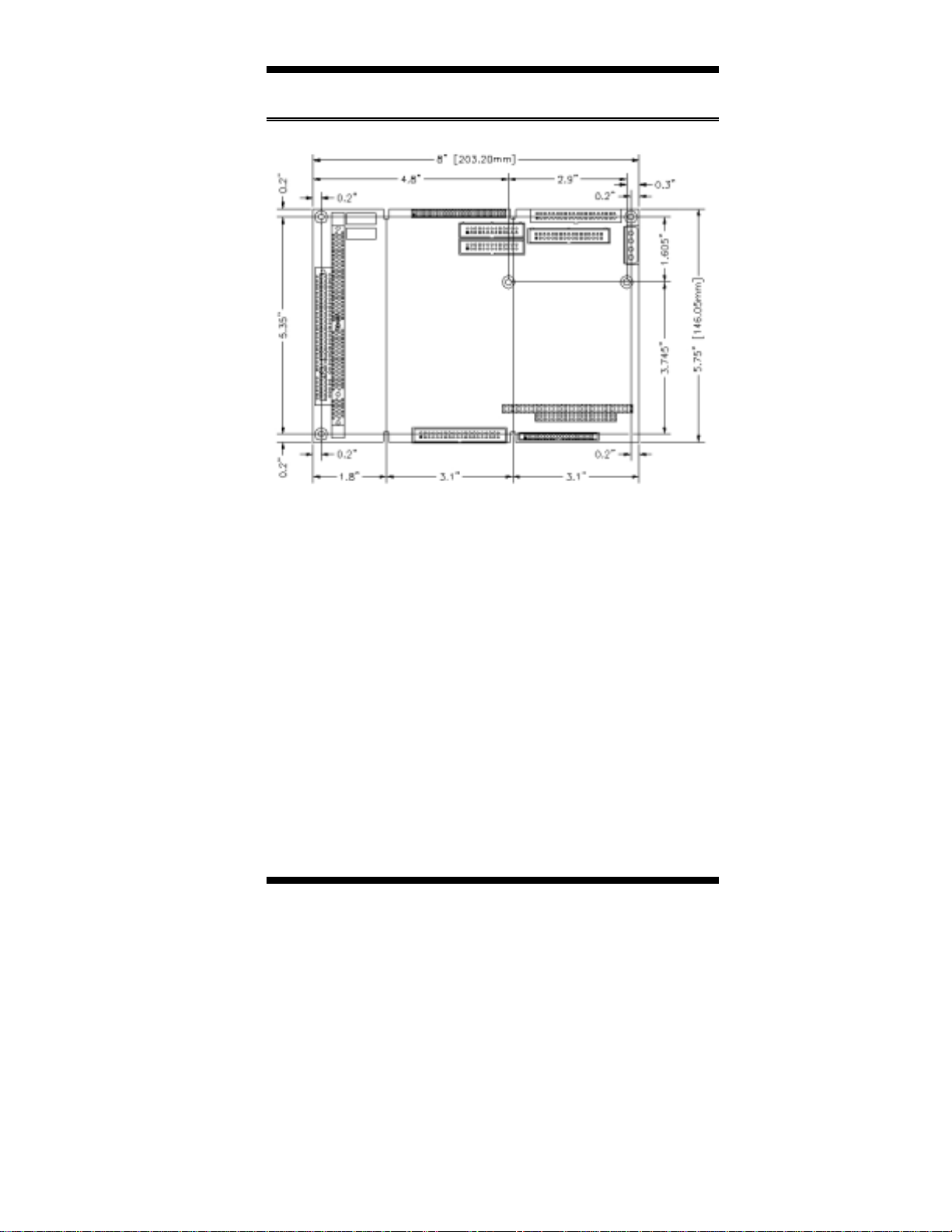
Introduction
Product Description
TL-EMBSBC 795 is a high-performance flexible embedded board
based on the VIA ProSavage TwisterT (PN133T) chipset. The chipset
is based on an innovative and scaleable architecture with proven
reliability. It is a two-chip set consisting of the VT8606 North Bridge
Controller and VT82C686B South Bridge Controller.
TL-EMBSBC 795 supports the VIA Eden/C3 processors that features
Native x86 execution, Integrated full-speed 192KB L1/L2 cache,
100/133MHz Front Side Bus, Advanced multimedia instruction set,
and MMX™ & 3DNow!™
The VT8606 integrated graphics accelerator supports 8/16/32MB frame
buffer using the system memory, integrated 2-channel 110MHz LVDS
interface and digital port for NTSC/PAL TV encoder. One or two
Ethernets can be supported by the Realtek 8139C single chip Ethernet
controller. Additional key features include support for two USB ports,
AC-97 link for audio, hardware monitoring, and power management.
The VT8606 integrated graphics accelerator supports 8/16/32MB
frame buffer using the system memory, integrated 2-channel 110MHz
LVDS interface and digital port for NTSC/PAL TV encoder. One or
two Ethernets can be supported by the Realtek 8139C single chip
Ethernet controller. Additional key features include support for two
USB ports, AC-97 link for audio, hardware monitoring, and power
management.
System memory is provided by one 168-pin DIMM socket that
accommodates SDRAM with a maximum capacity of 512MB. The
Award BIOS facilitates easy system configuration and peripheral setup.
Other advanced features include DiskOnChip flash disk support, 16-
level watchdog timer, and IrDA interface.
DiskOnChip flash disks are storage devices that has no moving parts
and emulates FDD/HDD with Flash/RAM/ROM offering reliable
data/program storage and long life span. They are reliable and suitable
for industrial or other harsh environments characterized by motion,
shock, vibration, adverse temperature, dust and humidity. Other
features include faster data access, longer MTBF, lower power
consumption, cost effective for small capacity and small form factor.