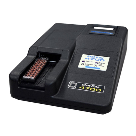
Awareness Technology Stat Fax 4200 User manual

© Awareness Technology Inc. 2008 Stat Fax®4200 Operator’s Manual Revised 2018 Rev. K
Stat Fax 4200
MICROPLATE READER
O
OP
PE
ER
RA
AT
TO
OR
R’
’S
S
M
MA
AN
NU
UA
AL
L
®

TABLE OF CONTENTS
1. Introduction ...................................................................................................... 1
1.1 Applications.............................................................................................................................. 1
1.1.1 Intended Use ..................................................................................................................... 1
1.1.2 Summary of the Instrument ............................................................................................... 1
1.1.3 Principles of Operation ...................................................................................................... 2
1.2 Warning Markings Inscriptions d’avertissement ...................................................................... 3
1.2.1 Safety Symbols Le Symboles de Sûreté........................................................................... 3
1.2.2 Safety Terms Terminologie de Sûreté .............................................................................. 3
1.3 Safety Precautions ................................................................................................................... 4
1.3.1 Disposal............................................................................................................................. 5
1.4 Specifications ........................................................................................................................... 6
1.5 Installation ................................................................................................................................ 8
1.5.1 General.............................................................................................................................. 8
1.5.2 Installation/Preparation...................................................................................................... 8
1.5.3 Load Paper ........................................................................................................................ 9
1.5.4 Touch Screen Description ............................................................................................... 10
1.6 Parts and Controls ................................................................................................................. 10
1.7 Checkout Procedure .............................................................................................................. 11
2. Operating Procedures ................................................................................... 12
2.1 Operating Precautions ........................................................................................................... 12
2.2 General Selections................................................................................................................. 12
2.3 Main Display Menu Options ................................................................................................... 13
2.3.1 Run Test.......................................................................................................................... 14
2.3.2 Settings ........................................................................................................................... 15
2.3.2.1 External Output....................................................................................................... 16
2.3.2.2 USB Mouse Connection ......................................................................................... 16
2.3.3 Manage Tests.................................................................................................................. 17
2.3.3.1 Multi-Test................................................................................................................ 18
2.3.4 Utilities ............................................................................................................................. 20
2.4 General Operation ................................................................................................................. 22
2.4.1 Bichromatic Differential Operation .................................................................................. 22
2.4.2 Loading and Formatting a Plate ...................................................................................... 22
2.4.2.1 Locating Controls.................................................................................................... 23
2.4.3 Reading a Plate............................................................................................................... 25
2.4.4 Unit of Measurement Codes (Unit Code) ........................................................................ 26
2.4.5 Offset Absorbance........................................................................................................... 27
2.4.6 Lamp Saver and Lamp Warmup ..................................................................................... 27
2.5 Modes of Operation ............................................................................................................... 28
2.5.1 Absorbance Mode ........................................................................................................... 30
2.5.1.1 Filter Selection........................................................................................................ 30
2.5.1.2 Blank....................................................................................................................... 31
2.5.2 Factor Mode .................................................................................................................... 31
2.5.3 Single Standard Mode..................................................................................................... 34
2.5.4 Multi-Point Modes (Point to Point, Regression and Cubic Spline) .................................. 36
2.5.4.1 - % Absorbance ...................................................................................................... 38
2.5.4.2 – Editing a Curve .................................................................................................... 39
2.5.4.3 – Select Axes.......................................................................................................... 40
2.5.4.4 – Controls ............................................................................................................... 42
2.5.5 Cut Off Mode ................................................................................................................... 43

3. Cleaning and Maintenance............................................................................ 50
3.1 Cleaning ................................................................................................................................. 50
3.1.1 Exterior ............................................................................................................................ 50
3.2 Maintenance........................................................................................................................... 50
3.2.1 Calibration and Linearity.................................................................................................. 50
3.2.2 Storage ............................................................................................................................ 51
4. Troubleshooting............................................................................................. 52
4.1 Messages and Flags .............................................................................................................. 52
4.2 Error Messages...................................................................................................................... 55
5. References...................................................................................................... 56
6. Optional Accessories .................................................................................... 57
6.1 Thermal Printer Paper............................................................................................................ 57
6.2 Dri-Dye®Check Strips............................................................................................................ 57
7. Information ..................................................................................................... 58
8. Appendix A SF_Capture ................................................................................ 59
9. Appendix B Updating Firmware.................................................................... 60
10. Appendix C Touchpad Alignment .............................................................. 60


Stat Fax®4200 Operator’s Manual Doc. 4200 Rev. K 1
1. Introduction
1.1 Applications
1.1.1 Intended Use
The Stat Fax®4200 is a compact, microprocessor-controlled, multi-purpose photometer
system designed to read and calculate the results of assays, which are read in 96 well
microplates or strip trays.
The Stat Fax®4200 may be used for in-vitro diagnostics. It is a user-programmable open
system with selectable plate formatting, alphanumeric test naming, automatic interpretation
options, duplicate well options, curve plotting and editing, flags and error messages from
which the user can create a menu of pre-programmed assays for instant recall.
Stat Fax®4200 is intended to be used as a stand-alone instrument without a PC but it has
a connection in the event a user wishes to download results. For a PC-controlled
microplate reader ask about the ChroMate TM Model 4300.
It is a general purpose instrument intended to be used by trained laboratory professionals
who are capable of selecting the appropriate features and options for each specific clinical
application. Contact your company’s instrument service provider to arrange for training if
the information provided in this manual is not sufficient for your applications.
FOR IN-VITRO DIAGNOSTIC USE
POUR L'USAGE DIAGNOSTIQUE IN VITRO
1.1.2 Summary of the Instrument
This instrument reads monochromatically (optional) or bichromatically (optional) and has
two models:
•Four-filter model (405, 450, 492, and 630 nm)
•Six-filter VIS model (405, 450, 492, 545, 600, and 630 nm)
Substitute filters in the range of 405 nm - 750 nm are available on special order models.

2 Stat Fax®4200 Operator’s Manual Doc. 4200 Rev. K
Summary of the Instrument (continued)
The Stat Fax® 4200 accepts all standard microplates. Trays containing microstrips may also
be read whether they are 12 wells in length, 8 wells or even partial strips.
Pre-programmed Modes - The basic calculations are permanently stored in
memory and include several single and multi-point equations. Provisions are
made in certain cases for reading specimens in duplicate and/or using the
mean reading in calculations. Each calculation mode is described in detail in
Section 2.5-Modes of Operation. The following calculation modes are
offered: Factor, Single Standard, Point to Point, Regression, Cubic Spline,
and Cut Off.
User-programmable Memory
The Stat Fax®4200 Microplate Reader’s software allows the operator to create, edit and
store assays. Standard curves are also stored in this memory. Test protocols remain
stored until either changed or deleted by the user.
1.1.3 Principles of Operation
The Stat Fax®4200 Microplate Reader’s optical system provides an economical and low
maintenance design which reads 8 wells simultaneously. A 96 well plate can be read and
printed in the absorbance mode in approximately twenty seconds.
Light from a lamp installed in a sealed light-tight compartment is filtered using a rotating
filter wheel. The filtered light is then divided into 8 channels using a fiber optic bundle.
The plate carrier precisely positions each row of 8 wells into the optical path for reading.
Light passing through the 8 wells is directed to 8 photo-detectors.
The filter wheel moves to a second position to read the 8 wells at a second wavelength.
Using bichromatic differential absorbance values corrects for optical imperfections in the
plastic wells and removes the effects of meniscus and turbidity.
The photo-detectors generate electronic signals which are amplified and interpreted by the
instrument circuitry.

Stat Fax®4200 Operator’s Manual Doc. 4200 Rev. K 3
1.2 Warning Markings Inscriptions d’avertissement
1.2.1 Safety Symbols Le Symboles de Sûreté
Symbols that may appear on the product:
Les symboles de sûreté peuvent apparaitre sur le produit:
WARNING
AVERTISSEMENT
Protective Ground
La Terre Electrique
CAUTION
L’ATTENTION
BIOHAZARD
BIOHAZARD
Risk of Shock
Risque de Choc
(Earth) Terminal
Prise de Terre
Refer to Manual
Se Rapportent a
Manuel
Risk of Infection
Risque d’infection
1.2.2 Safety Terms Terminologie de Sûreté
These terms may appear on the product: Les marques sur le produit:
These terms may appear in this manual: Les marques dans l’opérateur manuel:
DANGER
DANGER Le “de marque:
DANGER”
Indicates an injury immediately accessible as you read this marking
Indique le risque immédiat de dommages (assessible tandis que vous
lisez la marque)
WARNING
AVERTISSEMENT! Le “de
marque: WARNING”
WARNING statements identify conditions or practices that could
result in injury or loss of life. WARNING indicates an injury hazard not
immediately accessible as you read this marking.
Ces rapports identifient les conditions ou les pratiques qui pourraient
avoir comme conséquence les dommages ou les pertes humaines.
CAUTION
L’ATTENTION “Le de marque:
CAUTION”
CAUTION statements identify conditions or practices that could result
in damage to this product or other property.
Ces rapports identifient les conditions ou les pratiques qui pourraient
avoir comme conséquence les dommages a ce produit ou a toute
autre propriété.
BIOHAZARD
BIOHAZARDS are biological agents that can cause disease in
humans. Lab workers handling potentially infectious materials must
use universal precautions to reduce the risk of exposure to these
agents.

4 Stat Fax®4200 Operator’s Manual Doc. 4200 Rev. K
1.3 Safety Precautions
To assure operator safety and prolong the life of your instrument, carefully follow all instructions outlined
below.
Read Instructions Take time to read this manual carefully before using this instrument. Review
the following safety precautions to avoid injury and prevent damage to this
instrument or any products connected to it. To avoid potential hazards, use this
instrument only as specified. For best results, familiarize yourself with the
instrument and its capabilities before attempting any clinical diagnostic tests.
Refer any questions to your instrument service provider.
Servicing There are no user-serviceable parts inside the instrument. Refer servicing to
qualified service personnel. Use only factory-authorized parts. Failure to do so
may void the warranty.
Wear Protective
Apparel
Many diagnostic assays utilize materials that are potential biohazards.
WARNING: Always wear protective apparel and eye protection while using this
instrument.
Follow Operating
Instructions
WARNING: Do not use this instrument in a manner not specified by the
manual, or the protection provided by the instrument may be impaired.
Use Proper Power
Supply
WARNING: Use only the power supply specified for this product and certified
for the country of use.
Observe All Terminal
Ratings
WARNING: To avoid fire or shock hazard, observe all ratings and markings on
the instrument. Consult this manual for further ratings information before
making connections to the instrument.
Install as Directed This instrument should be installed on a sturdy, level surface capable of safely
supporting the instrument’s weight 12 lbs (5.4kg). The mounting surface should
be free of vibrations.
Provide Proper
Ventilation
Refer to the installation instructions for details on installing the product so it has
proper ventilation. The instrument should be surrounded by the following
clearances: 10cm around perimeter of unit, 10cm on top, 1.27cm bottom (1/2”).
Do Not Operate
Without Protective
Covers
WARNING: Do not operate this instrument with covers and panels removed.
Avoid Exposed
Circuitry
WARNING: Do not touch exposed connections and components when power is
present.
Avoid Excessive Dust
Do not operate in an area with excessive dust.
Do Not Operate With
Suspected Failures
WARNING: If you suspect there is damage to this instrument, have it inspected
by a qualified service person.
Do Not Operate in
Wet/Damp Conditions
WARNING: Do not operate instrument in wet/damp conditions.
Do Not Operate In An
Explosive Atmosphere
WARNING: Do not operate instrument in an explosive atmosphere.
Operating Precautions Be sure to run a sufficient number of controls in each assay. If controls are not
within their acceptable limits, disregard test results.
Keep Instrument
Surfaces Clean and
Dry
CAUTION: Solvents such as acetone or paint thinner will damage the
instrument.
√Do not use solvents to clean the unit. Avoid abrasive cleaners; the display
overlay is liquid-resistant, but easily scratched.
√Clean the exterior of the instrument with a soft cloth using plain water. If
needed, a mild all-purpose or nonabrasive cleaner may be used.
√Use as a disinfectant a 10% solution of chlorine bleach (5.25% Sodium
Hypochlorite) or 70% isopropyl alcohol.
√Take special care not to spill liquid inside the instrument

Stat Fax®4200 Operator’s Manual Doc. 4200 Rev. K 5
CAUTION! L’ATTENTION!
WARNING: If any materials are overturned during operation,
immediately set the power switch to OFF. This material should be
treated as potentially biohazardous. Appropriate cleanup and disposal
of biohazardous waste should be used.
Avertissement! Lors du fonctionnement, si on renverse des matériaux,
coupez immédiatement le courant. Placez le commutateur électrique a
AU LOIN(0). Traitez le matériel comme biohazardous, utilisant
approprie nettoient et des méthodes de disposition.
1.3.1 Disposal
Dispose of according to local regulations.
Before the instrument is removed from the laboratory for disposal or servicing, it must be
decontaminated.
Decontamination should be performed by a well-trained authorized person, observing all
necessary safety precautions. Instruments to be returned must be accompanied by a
decontamination certificate completed by the responsible laboratory manager. If a
decontamination certificate is not supplied, the returning laboratory will be responsible for
charges resulting from non-acceptance of the instrument by the servicing center or from
any authority’s intervention.
CAUTION! L’ATTENTION!
Caution: Treat all components during use and disposal as you would any
biohazardous material.
L’Attention: Utiliser et disposer des matériaux de la même manière que vous
utilisé et disposer des matières infectieuses.

6 Stat Fax®4200 Operator’s Manual Doc. 4200 Rev. K
1.4 Specifications
Photometric
Linear Measurement Range: ..................................... 0.0 to 4.0 Absorbance Units (A)
Photometric Accuracy: ............................................... +/- (1% +/- 0.010) 0.0 through 1.5 ABS
+/- (2% +/- 0.010) 1.5 through 3.0 ABS
Stability:...................................................................... Drift of no more than 0.005A in 8 hours
Light Source: .............................................................. Halogen lamp with lamp saver feature
Standard Wavelengths:.............................................. 405, 450, 492, and 630nm. 6-filter: 405,
450, 492, 545, 600, and 630nm. Filter
options from 405nm to 700nm.
Filter Type: ................................................................. IAD hardcoat interference, 10nm half
bandpass
Vessel:........................................................................ Standard 96-well microplates or strip
trays
Electronic
Display:....................................................................... Interactive touch screen 4.5”x3.5”
(14.5cm) LCD color graphic display
Printer:........................................................................ Thermal 64 characters per line, plus
graphics
Power Requirements:................................................. 100-240V AC, 1.2A, 50-60Hz (universal
input, auto sensing)
Microprocessor:.......................................................... eZ80, 64K EEPROM
Memory: ..................................................................... 2MB Flash Memory, 1MB RAM Memory
Interface: .................................................................... USB mouse; USB port used for thumb
drive interface for firmware updates
(mouse not included; thumb drive not
included)

Stat Fax®4200 Operator’s Manual Doc. 4200 Rev. K 7
Software
Speed: ........................................................................ Reads absorbance of 96 wells in about
10 seconds
Calculation Modes:..................................................... Factor, Single Standard, Point-to-Point,
Regression, Cubic Spline, Cut Off Mode
Test Storage:.............................................................. Stores 120 tests; stores all parameters
including wavelengths, calculations, unit
codes, linear and normal ranges,
standard values, test names, and
previous standard curve.
Other
Enclosure: .................................................................. Flame-retardant ABS/PVC alloy material
cover with aluminum base
Dimensions: ............................................................... Approximately 13.5”Wx17”Dx8-1/4”H
(34.3cmx43.2cmx21cm)
Weight ........................................................................ 12 lbs (5.5kg)
Certifications: ............................................................. CE, ETL listed,
NRTL listed (USA/CAN)
Recommended Environmental Conditions
Indoor use
Mains supply voltage: Fluctuations not to exceed + 10% of
nominal voltage
Recommended Operating Temperature .................... 18-35°C
Recommended Operating Humidity:.......................... less than 80%
Storage Temperature: ................................................ 10 to 50°C
Accessories sold separately: Thermal paper (contact your dealer)
NOTE: Although it may be safe to operate in these conditions, it may not be
suitable for the performance of your tests. Check with your reagent supplier.

8 Stat Fax®4200 Operator’s Manual Doc. 4200 Rev. K
1.5 Installation
1.5.1 General
Carefully unpack the instrument, removing it from its plastic bag. Report any damage to
your freight carrier at once. Retain the original packing material for future use in the event
that the instrument is shipped to another location or returned for service. Items packed with
the instrument include:
1.5.2 Installation/Preparation
Instrument Placement
and Use
Place the instrument on a flat working surface capable of safely
supporting the weight of the instrument, approximately 5.4 kg (12lbs).
A clearance of at least 8cm (3”) around the instrument is required to
assure optimal ventilation.
Assure Clean Power
Availability
The circuit used should be substantially free of large voltage
transients (Kilovolt amp loads) such as large pumps, large
centrifuges, refrigerators and freezers, air conditioners, large
autoclaves, ovens, and dryers. The instrument may fail to operate
normally if the power supply is interrupted. If this occurs, turn the
instrument off for a moment. When the instrument is turned back on,
it will resume normal operation, but data that was not stored in
nonvolatile memory will be lost. If power fluctuations or loss are
frequent, an Uninterruptible Power Supply (UPS) is recommended.
Power Switch Position The ON/OFF switch is on the back of the instrument. The power
switch should be in the OFF position (down) before connecting the
power cord to the power supply.

Stat Fax®4200 Operator’s Manual Doc. 4200 Rev. K 9
Power Cord
Requirements
With the power switch in the OFF [down] position, insert the DC
connector attached to the end of the power supply module cable to
the instrument. Insert the mating end of the AC power cord to the
inlet of the power supply module, and plug the other end of the AC
power cord into an AC outlet. Use only the power cord and supply
module specified for this product and certified for the country of
use.
For 110-120 V used in the United States, use a UL listed cord set
consisting of an 18 AWG, Type SPT-1 two conductor cord
maximum 3 meters (10 feet) in length, rated 7 A, 125 V, with a
polarized parallel blade type attachment plug.
For 220-240 V used inside the United States, use a UL listed cord as
above, except rated 250V.
For other locations, use the power cord certified for the country of
use.
1.5.3 Load Paper
Figure 1.5.3-1 Paper compartment lid
Locate the roll of thermal printer paper P/N
150003.
Press down on the printer paper compartment
release button (A) and the paper compartment lid
will open.
Place the paper roll in the well such that the
leading edge of the paper feeds upward from the
front of the printer as shown.
Figure 1.5.3-2 Printer paper installed
Pull up at least 1 inch of paper and then
press the compartment cover down until it
snaps closed. Turn the power switch OFF
and back ON. The wake up routine will
follow. The printer will print several lines.
Wait until it has stopped. If there is no
printing, the internal printer is disabled
(reference Section 2.3.2 Settings).
NOTE: The printer manufacturer strongly
recommends the use of thermal paper
part number 150003 to reduce lint and
extend printer life. Contact your dealer for
replacement rolls.
A
Printer paper
compartment
release button

10 Stat Fax®4200 Operator’s Manual Doc. 4200 Rev. K
1.5.4 Touch Screen Description
The touch screen responds to touch pressure which causes electrical contact between the
conductive and resistive layers. The touch screen provides the following advantages:
•High touch resolution
•Pressure sensitive, works with any stylus
•Not affected by dirt, dust, water or light
•Durable technology
1.6 Parts and Controls
The following terms are used in this manual to describe parts and controls of the Stat Fax®4200
microplate reader. More details on the operation of each feature are provided in Section 2-
Operating Procedures.
A) Door open
B) Printer and printer
paper compartment
C) Display
Figure 1.6-1 Front of instrument
A) Power supply module
B) Power switch
C) Power supply connection
D) USB Port
E) USB ports: mouse and thumb drive
F) Stylus
Figure 1.6-2 Connections
B
A
C

Stat Fax®4200 Operator’s Manual Doc. 4200 Rev. K 11
1.7 Checkout Procedure
Follow this procedure to verify that the instrument is ready for use.
Checkout Procedure
Visually confirm the following items:
√Power supply is connected to the unit and the power plug is inserted into an AC
outlet.
√
Power switch is set to OFF.
The instrument is now ready for power-up. Confirm that the instrument responds as
described.
√Set the power switch to the ON position.
The printer will print out the
instrument model, serial
number, laboratory name (if
defined under the Settings
menu Laboratory Name option;
the default is no laboratory
name), firmware version,
revision level, date and time
(Figure 1.7-2).
Click Tray Out and make sure
door opens and microplate tray
extends out.
Click Tray In and make sure
door closes.
Before running any assays,
read at least one plate in
absorbance mode to verify
plate carrier operation
If the instrument still produces
results other than those
described here, refer to Section
4. Troubleshooting, or contact
your dealer for assistance.
Figure 1.7-1 Power up Screen Display
Stat Fax 4200 Ver: Eng-01.26.00
Laboratory Name (if defined)
Serial Number: 9999
12-20-2018 16:34:40
Figure 1.7-2 Representation of the power up
print out
Stat Fax
4200
Loading …
AWARENESS
TECHNOLOGY
INC

12 Stat Fax®4200 Operator’s Manual Doc. 4200 Rev. K
2. Operating Procedures
2.1 Operating Precautions
•Avoid lifting, leaning or turning the instrument over when a plate is in place.
•Be sure to run a sufficient number of controls in each assay. If controls are not within
their acceptable limits or if incomplete, disregard test results.
2.2 General Selections
For every test, the instrument will require a mode selection and filter combination. Thereafter,
only those questions that pertain to the mode selected will be asked. In the Absorbance Mode, for
example, there are no further selections required.
Review the following questions before beginning a test (refer to the reagent kit insert for required
information):
1. How will absorbance readings be converted into a final result?
2. Is a Blank required? Which filters are optimal? (primary and differential
wavelengths)
3. How many calibrators will be used? NOTE: For the purpose of this manual, the
terms calibrator and standard are used interchangeably to designate reference
materials of known concentrations.
4. What is the calibrator value or values?
5. Will calibrators and /or specimens be read in duplicate, or singly? NOTE: For the
purpose of this manual, the terms specimen and sample are used interchangeably
to mean materials of unknown concentrations.
6. Will locations of one or more controls be marked? If so, indicate plate number,
row number, and well number for each.
7. Will acceptance cutoffs or ranges for controls be entered for automatic
comparison? If so, what cutoffs or ranges are to be used for each?
8. Will a cutoff value be used to label positive samples? If so, the value that begins
the positive range will be required.
9. Will a cutoff value be used to label negative samples or define an equivocal zone?
If so, results less than which cutoff should be labeled as negative?
10. Will only a partial plate be read?

Stat Fax®4200 Operator’s Manual Doc. 4200 Rev. K 13
2.3 Main Display Menu Options
The Main display menu options are:
•Run Test explained in Section 2.3.1
•Settings explained in Section 2.3.2
•Manage Tests explained in Section 2.3.3
•Utilities explained in Section 2.3.4
•Tray In – the plate carrier transports the plate into the and the door closes
•Tray Out – the door opens and the plate carrier extends out for the ease of
inserting a test plate on the carrier
Lamp status indicator Time Reprint button
Figure 2.3-1 Main display menu screen
The status line displays the Lamp status (OFF or ON) and the time. The printer button (PRN) has
two options: 1. to advance the paper, 2. to reprint the last 64 lines of data. NOTE: PRN does not
print graphs, only data.

14 Stat Fax®4200 Operator’s Manual Doc. 4200 Rev. K
2.3.1 Run Test
The Run Test feature allows the operator to recall user tests that have been stored in the
instrument’s memory (see example in Figure 2.3.1-1). The Stat Fax®4200 stores up to
120 complete test setups in nonvolatile memory, making it easy for the user to recall
complete test configurations.
Select Run Test from the Main display. Tests programmed and saved on the instrument
will display sorted by their test number. Each of the test parameters, including the mode,
wavelengths, standards, units, and the ranges are all stored for reuse.
Blanks and standards (including entire standard curves) that have been read are also
saved. When the test is recalled, the user has the option of using the previous saved
curve or reading a new one.
Figure 2.3.1-1 Run Test - Example of stored test menu
Feature Function
Arrows
Use the ^ UP and VDOWN arrow keys to highlight
selection; use the >> side arrows to advance to
the next screen; use << arrows for previous
screen
Select
The highlighted test is executed once the Select
key is pressed
By #
Allows the user to enter a specific test number to
recall.
Cancel
Returns to the main power on display screen
1 – TSH
2 – T3
3 – T3 Uptake
4 – T4
5 – T4 Total
6 – FSH
7 – hCG
8 – LH
9 – Testosterone
SAMPLE
By #
Cancel
Select
v
<<
>>

Stat Fax®4200 Operator’s Manual Doc. 4200 Rev. K 15
2.3.2 Settings
Select the Settings option on the main display screen and the Unit Settings will display:
Unit Settings
Adjust Date and Time
Printer Setup
Lamp Control
Plate Assignment
Sound Settings
Laboratory Name
External Output
Plate Print Format
Figure 2.3.2-1 Unit Settings
The functions of the Unit Settings features are:
Feature Function
Adjust Date and
Time
Provides access to the Set Time option Hours, Minutes, Seconds
as well as Month, Day, Year
Printer Setup
Enables/disables the internal printer. Graphs can be printed when
the internal printer is set to OFF. Allows the contrast to be
adjusted light to dark. It is advisable to print at contrast level set at
3. Higher t levels may degrade after several lengthy printouts.
Text height options are small, medium and large.
Lamp Control Lamp idle feature will automatically turn off the lamp; the default
setting is 600 seconds (10 minutes). Lamp Warm up range is
between 45 and 240 seconds (45 seconds is the default setting).
Plate Assignment Offers plate format options such as 8 way or 12 way; duplicates
side by side.
Sound Settings Provides access to and status of touch screen sound settings (ON
or OFF), and sound volume (1=low to 8=high). Sound options are:
start up sound, key press & release and other sounds (i.e. sound
when the Quit button is selected).
Laboratory Name Allows a laboratory named to be entered; laboratory name will
print out (reference Checkout Procedure in Section 1.8).
External Output Allows external output to be turned ON or OFF. Reference the
External Output Section 2.3.2.1 for setup instructions.
Plate Print Format User can select either a 1 to 12 or H to A printout of plate data.
Arrow Keys: Utilize the
arrow keys to scroll up and
down the list of options or
press the option directly
from the list; the option will
highlight
Select: The high-lighted
option is executed once the
Select key is pressed
^
v
Select
Done

16 Stat Fax®4200 Operator’s Manual Doc. 4200 Rev. K
2.3.2.1 External Output
To enable output to be sent to a personal computer, a user must use a software
application such as SF_Capture to transmit and store data from the Stat Fax®4200
and have the following in place:
•Power on the instrument and set the External Output to “ON” by: (a) selecting
Settings from the main display, (b) highlight External Output on the Unit Settings
display, (c) press the Select button, (d) on the External Output Setup display
select the ON button and ensure that the Status field displays ON, (e) select the
Save button, and then, (f) select the Done button.
•Connect the type B end of the USB cable to the type B port of the
instrument.
•With the personal computer (PC) powered on, connect the type A end of the USB
cable to a USB port on the PC.
Type A
Figure 1 USB Type A port and connector
Type B
Figure 2 USB Type B port and connector
2.3.2.2 USB Mouse Connection
To use a USB mouse with the Stat Fax®4200, be sure that the mouse is connected
to the USB port A on the instrument before the instrument is powered on. If the
mouse is plugged in after the instrument is on, it will not be operational.
Table of contents
Other Awareness Technology Laboratory Equipment manuals
Popular Laboratory Equipment manuals by other brands

EnGenius
EnGenius EPE-4818G Installation guides

CoolLED
CoolLED pE-800 quick start guide

Cole Parmer
Cole Parmer Stuart SB3/1 instruction manual

GE
GE AxiChrom 50 operating instructions

Schier Products
Schier Products FS-DUO installation guide

MO BIO Laboratories
MO BIO Laboratories UltraClean GelSpin DNA instruction manual

SYSMEX
SYSMEX ogt Cytocell Multiprobe OctoChrome Instructions for use

Xiaomi
Xiaomi EraClean CW-BT01 user manual

Thermo Scientific
Thermo Scientific EA IsoLink IRMS System operating manual

Spicer Consulting
Spicer Consulting SC28 user manual

Tuttnauer
Tuttnauer T-Top 10 Operation and maintenance manual

Owen Mumford
Owen Mumford AutoSqueeze OP6100 instructions