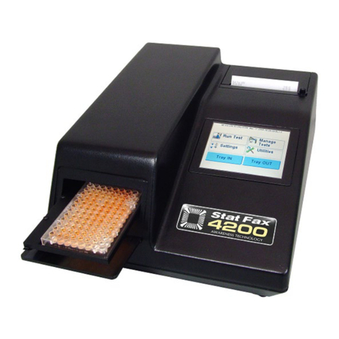
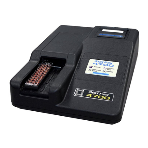
Awareness Technology Stat Fax 1904 Plus User manual

Stat Fax® 1904 Plus
Operator’s Manual
Copyright 1989-2005 Awareness Technology, Inc. Revised 01/05. Doc. P1904P Rev. I


Table of Contents
1.INTRODUCTION ................................................................................................ 1
1.1Applications ..........................................................................................................1
1.1.1IntendedUses..............................................................................................1
1.1.2SummaryoftheInstrument ...........................................................................1
1.1.3Principles of Operation ................................................................................2
1.2WarningMarkings .................................................................................................3
1.2.1SafetySymbols............................................................................................ 3
1.2.2SafetyTerms................................................................................................3
1.3SafetyPrecautions................................................................................................4
1.4Installation .............................................................................................................6
1.4.1GeneralInstallation.......................................................................................6
1.4.2PaperInstallation .........................................................................................7
1.4.3CheckoutProcedure ....................................................................................8
1.5Parts and Controls ................................................................................................9
1.5.1Partsof theInstrument..................................................................................9
1.5.2 KeyboardFunctions ...................................................................................10
1.6InstrumentSpecifications .................................................................................... 11
2. OPERATING PROCEDURES ........................................................................... 13
2.1GeneralFunctions...............................................................................................13
2.1.1StartUp......................................................................................................13
2.1.2ALTMenu...................................................................................................13
2.1.3SetTime ....................................................................................................14
2.1.4Lamp Warm Up..........................................................................................14
2.1.5TemperatureControl.............................................................................................14
2.1.6 Selecting a Mode.......................................................................................15
2.1.7Filter Selection...........................................................................................15
2.2GeneralOperation ..............................................................................................16
2.2.1BichromaticDifferential Operation .............................................................16
2.2.2Blanking.....................................................................................................16
2.2.3Unit of Measurement Codes(Unit Code)....................................................17
2.2.4 Ranges ......................................................................................................18
2.2.5Printer........................................................................................................18
2.2.6Lamp Saver Feature ..................................................................................19
2.2.7 Flags and Error Messages.........................................................................19

2.2.8Calibration and Linearity ............................................................................20
2.3 Modes of Operation ............................................................................................21
2.3.1Absorbance Mode .....................................................................................21
2.3.2 Single Standard Mode ...............................................................................21
2.3.3 Factor Mode ..............................................................................................22
2.3.4Programmable Mode(Multipoint) ...............................................................23
2.3.5Multipoint %AbsMode ..............................................................................24
2.3.6Rate Mode.................................................................................................25
2.4TestMenus..........................................................................................................28
2.4.1Pre-programmedTestNames....................................................................28
2.4.2UserTestMenu ..........................................................................................29
3.ADDITIONALTIPSANDINFORMATION........................................................... 31
3.1Restoring Electronic Calibration..........................................................................31
3.2OperatingPrecautions ........................................................................................32
3.2.1Minimize operator error..............................................................................32
3.3Maintenanceand Service....................................................................................33
3.3.1PreventingTrouble .....................................................................................33
3.3.2TroubleshootingGuide ...............................................................................33
3.4 Accessories........................................................................................................35
3.4.1Mosquito™ ................................................................................................35
3.4.2REDI-CHECK® .........................................................................................36
4.REFERENCES................................................................................................. 37
5.SAMPLEPRINTOUTS ..................................................................................... 39
6.USER TEST MENU LOG ................................................................................. 43
7.CONTACTINFORMATION ............................................................................... 45

Awareness Technology Inc. Stat Fax 1904 Plus Operator’s Manual Rev. I 1
1. INTRODUCTION
1.1 Applications
1.1.1 Intended Uses
Stat Fax®1904 Plus is a laboratory instrument intended for in-vitro diagnostic use. It is a
compact, microprocessor-controlled, bichromatic photometer system with six filters and
37°C incubation. The standard diameter for the round tubes used with the instrument is
12mm. The instrument can be used to measure absorbances or concentrations based on
standard points or rates of change, as described in this manual. This general purpose
instrument is intended to be used by trained laboratory professionals.
1.1.2 Summary of the Instrument
The primary function of Stat Fax®1904 Plus is to read and calculate the results of both
endpoint and kinetic colorimetric assays. Any test procedure that calls for absorbance
reading at or near one of the available wavelengths can be performed with this
instrument. Additionally, the most commonly applied data reduction formulae are pre-
programmed to further facilitate laboratory testing. These programs include rate
calculation and single- and multipoint standardization. Through the alphanumeric display,
the instrument prompts the operator to read the tubes in the appropriate sequence. It then
performs the necessary calculations and prints out test results.
In addition to the six primary filter choices, the operator may select a differential
wavelength for bichromatic reading in any operating mode. This corrects for imperfections
in the test tubes and often removes the effects of unwanted turbidity.
Each mode of operation is self-prompting, to reduce error and simplify operation. In all
modes the instrument will reference air, request and read the blank tube, and then read
and print automatically whenever a tube is inserted. In the Absorbance Mode, the
instrument reads and prints differential absorbances using operator selected filters. In the
Factor Mode, the absorbances are multiplied by the operator-entered factor and then
reported as concentrations. The Standard Mode calculates concentrations according to
Beer’s Law based on a single standard reading. The Multipoint % Abs Mode reports the
sample absorbances as percent of the first standard in a multipoint curve. The
Programmable Mode, or Multipoint Mode, calculates concentrations according to
Beer’s Law, based on the point-to-point connection of multiple (up to 7) standard points.
Sample blanking is available in all modes except Absorbance Mode and Rate Mode. The
Rate Mode determines the average change in absorbance per minute and then either
multiplies it by the operator-entered rate factor or bases the concentration on a previously
read standard. Intermediate absorbance readings of the kinetic assay may be plotted on
the internal graphics printer to verify linearity of the reaction. The Rate Mode includes a
“Batch” option that permits kinetic assays to be run simultaneously as well as
consecutively.

2Stat Fax 1904 Plus Operator’s Manual Rev. I Awareness Technology Inc.
Stat Fax®1904 Plus includes non-volatile memory, a feature that allows test parameters
and standard curves to be stored for rapid future recall. The names of 30 of the most
common assays are stored in the first 30 test positions, which enables the user to
program his or her assays' test parameters under the appropriate names. In addition,
other tests can be stored by number in a “User Menu” (and named via the keypad) with a
capacity of 69 total tests.
Stat Fax®1904 Plus also contains a 37°C incubation block with 12 stations. The incubator
will accommodate 12 mm diameter round test tubes (size may be specified at time of
purchase). A similar self-monitoring incubation system is built into the read well for
temperature controlled absorbance reading at 37°C This is often essential to the precision
of rate determinations.
Stat Fax®1904 Plus offers quick, accurate, reproducible results; maintenance-free, easy
operation; versatility, and economy. Stable factory calibration, a durable design, and a
timed lamp saver feature further assure the continuous reliability of Stat Fax®1904 Plus.
1.1.3 Principles of Operation
Light energy from the halogen lamp is focused by a lens, directed through an aperture,
and then passed horizontally through the sample. A continuously rotating wheel positions
the filters so that readings can be taken very quickly at 2 wavelengths. (Using bichromatic
differential absorbance values corrects for optical imperfections in the tubes.) A
photodetector converts transmitted light energy into electrical signals, which are amplified
andinterpreted.

Awareness Technology Inc. Stat Fax 1904 Plus Operator’s Manual Rev. I 3
1.2 Warning Markings
1.2.1 Safety Symbols
Safety symbols which may appear on the product:
WARNING Protective Ground CAUTION BIOHAZARD
Risk of Shock (Earth) Terminal Refer To Manual Risk of Infection
FUSE: For continued protection against the risk of fire, replace
only with fuse of the specified type and current ratings.
Disconnect equipment from supply before replacing fuse.
1.2.2 Safety Terms
These terms may appear on the product:
DANGER indicates an injury immediately accessible as you read the marking.
WARNING indicates an injury hazard not immediately accessible as you read this
marking.
CAUTION indicates a hazard to property including the product.
Terms which may appear in this manual:
WARNING: Warning statements identify conditions or practices that could
result in injury or loss of life. WARNING indicates an injury hazard not
immediately accessible as you read the marking.
CAUTION: Caution statements identify conditions or practices that could
result in damage to this product or other property.
BIOHAZARD: Biohazards are biological agents that can cause disease in
humans. Lab workers handling potentially infectious materials must use
universal precautions to reduce the risk of exposure to these agents.

4Stat Fax 1904 Plus Operator’s Manual Rev. I Awareness Technology Inc.
1.3 Safety Precautions
To assure operator safety and prolong the life of your instrument, carefully follow all
instructions outlined below.
Read Instructions
Review the following safety precautions to avoid injury and prevent damage to this
instrument or any products connected to it. To avoid potential hazards, use this
instrument only as specified. For best results, familiarize yourself with the instrument and
its capabilities before attempting any clinical diagnostic tests. Refer any questions to your
instrument service provider.
Servicing
There are no user-serviceable parts inside the instrument. Refer servicing to qualified
service personnel. Use only factory authorized parts. Failure to do so may void the
warranty.
Personal Protective Equipment
Many diagnostic assays utilize materials which are potentially biohazardous. Always
wear protective apparel and eye protection while using this instrument.
Follow Operating Instructions
Do not use the instrument in a manner not specified by the manual or the protection
provided by the instrument may be impaired.
Use Proper Power Cord
Use only the power cord specified for this product and certified for the country of use.
Ground the Product
This product is grounded through the grounding conductor of the power cord. To avoid
electric shock, the grounding conductor must be connected to earth ground. An alternate
method is to attach a ground strap from the external grounding terminal on the rear panel
of the instrument to a suitable ground such as to a grounded pipe or some metal surface
to earth ground.
Observe All Terminal Ratings
To avoid fire or shock hazard, observe all ratings and markings on the instrument.
Consult this manual for further ratings information before making connections to the
instrument.
Install as Directed
The Stat Fax®1904 should be installed on a sturdy, level surface capable of supporting
the instrument’s weight (approx. 10 lbs, 4.5 kg) safely for safety and ventilation purposes.
The mounting surface should be free of vibrations.
Provide Proper Ventilation
Refer to the installation instructions for details on installing the product so it has proper
ventilation. The instrument should be surrounded by the following clearances: 8 cm
around perimeter of unit and 8 cm on top.
Do Not Operate Without Covers
Do not operate this instrument with covers and panels removed.

Awareness Technology Inc. Stat Fax 1904 Plus Operator’s Manual Rev. I 5
Use Proper Fuse
Use only the fuse type and rating specified by the manufacturer for this instrument. Use
of a fuse with an improper rating may pose a fire hazard. Refer to the section on Trouble
Shooting for details on fuse replacement.
Avoid Exposed Circuitry
Do not touch exposed connections and components when power is present.
Avoid Excessive Dust
Do not operate in an area with excessive dust.
Do Not Operate With Suspected Failures
If you suspect there is damage to this instrument, have it inspected by a qualified service
person.
Do Not Operate in Wet/Damp Conditions
Do Not Operate In An Explosive Atmosphere
Keep Instrument Surfaces Clean and Dry
Solvents such as acetone or thinner will damage the instrument. Do not use solvents to
clean the unit. Avoid abrasive cleaners; the display overlay is liquid-resistant, but is easily
scratched.
The exterior of the instrument may be cleaned with a soft cloth using plain water. If
needed, a mild all-purpose or nonabrasive cleaner may be used. A 10% solution of
chlorine bleach (5.25% Sodium Hypochlorite) or 70% isopropyl alcohol may be used as a
disinfectant. Take special care not to spill liquid inside the instrument.
OperatingPrecautions
Be sure to run a sufficient number of controls in each assay. If controls are not within
their acceptable limits, disregard test results.
BiohazardPrecautions
BIOHAZARD
WARNING - If any materials are overturned during operation, immediately set
the power switch to OFF (0). This material should be treated as potentially
biohazardous. Appropriate cleanup and disposal of biohazardous waste should be
used.

6Stat Fax 1904 Plus Operator’s Manual Rev. I Awareness Technology Inc.
1.4 Installation
1.4.1 General Installation
UnpackInstrument
Carefully unpack the instrument, removing it from its plastic bag. Report any damage to
your freight carrier at once. The box should also contain the User’s Manual and a serial
cable.
NOTE: Retain the original packing material for future use in the event that the instrument
is shipped to another location or returned for service.
Instrument Mounting and Use
Place the instrument on a flat working surface capable of safely supporting the weight of
the instrument (approx. 10 lbs, 4.5 kg). Excessive vibration during reading may cause
poor repeatability; thus, a sturdy working surface is required. A clearance of at least 3
inches (8cm) around the instrument is required to assure optimal ventilation. It is
recommended that the instrument be operated within an ambient temperature range of
18-35°C and humidity of less than 85%.
Power Switch Position
When installing the power cord or if changing the setting on the voltage select switch the
unit should be turned off. Look at the rear panel of the instrument to check that the power
switch is in the Off position. A diagram of the rear panel can be found in Section 1.5
“Parts and Controls”.
Power Cord Requirements
Use only the power cord specified for this product and certified for the country of use. For
110-120 V units used inside the US use a UL listed cord set consisting of a minimum 18
AWG, Type SVT or SJT three conductor cord, maximum 3 meters (10 feet) in length,
rated 10 A, 125 V, with a parallel blade, grounding type attachment plug.
For 220-240 V units used inside the US use a UL listed cord as above, except rated 250
V, with a tandem blade, grounding type attachment plug. The cord set provided by the
manufacturer meets these requirements.
Safety Grounding
Do not alter or defeat the safety grounding methods provided. To avoid the risk of electric
shock, the third prong of the AC power plug must be connected to conductive parts
internal to the equipment. Internal fasteners to grounding points are marked by the IEC
417 symbol 5019 . DO NOT loosen or remove these fasteners or connections. An
alternate method of grounding is provided by connecting the grounding terminal located
on the rear panel, to a suitable ground.
To avoid electric shock, the power cord protection ground conductor must be connected
to ground.
Voltage Select Switch
Locate the voltage select switch on the rear panel. This is a 2-position slide switch that
will configure the instrument to accept either 230V or 115V input. Do not connect
equipment to the power supply before changing the line voltage selection switch.

Awareness Technology Inc. Stat Fax 1904 Plus Operator’s Manual Rev. I 7
Warning: To prevent permanent damage to the instrument, this switch must
be set for the appropriate input voltage before powering up.
When you can see the 230V label, the instrument is set for 230V input. If you plug the
instrument into a 115V power supply while 230V is selected, the instrument will have
insufficientoperating power.
To select 115V input, insert a straight screwdriver blade (or similar instrument) into the
slot on the switch, and slide it into its alternate position. Upon sliding the switch, you will
see the 115V label appear.
Warning: If the instrument is configured to accept 115V and you plug it into a
230V power supply, the fuses will blow and permanent damage to the electronics
may result.
Assure Clean Power Availability
The circuit used should be substantially free of large voltage transients (Kilovolt amp
loads) such as large pumps, large centrifuges, refrigerators and freezers, air conditioners,
large autoclaves, ovens, and dryers. The instrument may fail to operate normally if the
power supply is interrupted. If this occurs, turn the instrument off for a moment. When
you turn the instrument back on, it will resume normal operation, but a standard curve
which was not stored in non-volatile memory will be lost.
FuseRequirements
The fuses are located internally in the instrument; there are two fuses, fusing both sides
of the main power supply. Fuse failure is a very rare occurrence and should indicate
malfunction of the equipment requiring service by qualified personnel.
The fuses used within this instrument are 6/10 Amp T rated (slow blow), 250 V. Cartridge
size is 3AG or size “0”, dimensions 1/4 x 1-1/4” (6.3 x 32 mm). For continued protection
against risk of fire, use the same fuse for either 115 or 230 V line voltage selection.
Disconnect power cord from mains supply before replacing fuses.
1.4.2 Paper Installation
Remove the optional paper cover by pinching the sides together and pulling up. Unroll
about 10 inches of paper and place the roll on the table behind the instrument. Feed a
cleanly cut edge of the paper from the back into the printer, along the top of the metal
guide inside the printer paper well. A ragged edge or wrinkled paper will be difficult to load
and could cause a paper jam. Feed just over 1 inch of paper in and then press the paper
advance key (labeled Paper) several times to automatically feed the paper through the
printer. You will see the paper appear through the paper slot in front. Drop the roll of
paper into the printer paper well in back, spooling up any loose paper. If you have
difficulty, cut a new straight edge before trying again. Replace the paper cover by
pinching the sides together and pushing it down over the roll of paper. Insert the slotted
tabs into the printer panel. Use of the cover is optional for holding the roll of paper down in
the printer paper well.

8Stat Fax 1904 Plus Operator’s Manual Rev. I Awareness Technology Inc.
1.4.3 Checkout Procedure
Perform the following checkout procedure after installation. If any portion of this procedure
does not check out properly, contact your dealer to arrange for assistance.
Turn the power switch on. The printer should print “Stat Fax 1904Plus :mX,” where m
indicates Mosquito™aspiration flowcell capability and Xis the software revision level, then
“01/01/99 13:37,” representing the date and the time. The display shows “STAT FAX
1904P” momentarily, then “B ##.# H C ##.# H.” Band Cindicate the block and cell
(read well) temperatures, and Hindicates that the heater is on. Listen for the fan. Look
into the tube well for light coming from the optical system.

Awareness Technology Inc. Stat Fax 1904 Plus Operator’s Manual Rev. I 9
1.5 Parts and Controls
1.5.1 Parts of the Instrument
The following labeled sketches will help you locate and identify the major parts of Stat
Fax®1904 Plus. More details on the operation of each feature are provided in section 2 -
OperatingProcedures.
A Temp. Controlled Cuvette Well (optical system below)
B Cover
C Incubator
D Printer Paper Well
(with paper cover)
E Printer Paper Slot
F Alphanumeric Display
G Keyboard
H Power Switch
I Power Cord Connection
J Serial Port
K Voltage Select Switch
Stat Fax®Bichromatic Photometer System
designed and manufactured by Awareness Technology, Inc.
Palm City, FL
A
B
CD
E
F
G
H
I
J
K

10 Stat Fax 1904 Plus Operator’s Manual Rev. I Awareness Technology Inc.
1.5.2 Keyboard Functions This key is used to enter a
NEGATIVE sign. It is also used to
access alternate OPTIONS such as
saving a test, turning the printer off,
and setting the date.
The PAPER key advances the printer
paper forward one line each time it is
pressed.
The CLEAR key is used to erase a
typing error when information is
being entered. Pressing twice clears
the mode. In rate modes using the
MosquitoTM, this key will clear the
sample when the printer is off, and
will also terminate a reading.
The ENTER key is used to tell the
instrument when you are finished
entering information, or when you
want to re-read a sample tube.
Pressing the
BLANK key causes
automatic blanking
of the next tube
read.
The DECIMAL POINT
and Test MENU key also
selects printing of Rate
Intervals and GRAPHS.
The LAMP key turns
the lamp on and off.
The numeral keys serve several functions. As numbers, they are used to enter calibration
information and to make selections for filters, units, and stored test protocols.
Any key serving multiple functions will respond to the displayed request for information.
ABS, STND, FAC, PGM, %ABS, and RATE are the keys used to select a mode of
operation. The previous mode is erased when a new mode is selected.
ABS stands for Absorbance Mode.
STND stands for Single Standard Mode
FAC stands for Factor Mode
PGM stands for Programmable Mode - Multipoint Mode
%ABS stands for Percent Absorbance Multipoint Mode
RATE stands for Rate Mode
Use the key labeled Menu to access the test menu.
Pressing the FILT key causes the printer to list out the key assignments of the filters.
Key I is 340nm, key 2 is 405nm, key 3 is 492nm, key 4 is 532nm, key 5 is 580nm, and
key 6 is 630nm.
Pressing the TEMP key displays the temperatures in the incubation block and in the cell.
It also offers an option to turn the cell temperature on and off using the 1 and 0 keys.

Awareness Technology Inc. Stat Fax 1904 Plus Operator’s Manual Rev. I 11
1.6 Instrument Specifications
Linearmeasurementrange:....................... 0.00 to 2.50 Absorbance Units (A)
Photometric accuracy :.............................. ± (1% of the reading + 0.005 A) at 1.5A
± (2% of the reading + 0.005 A) at 1.5-2A
Stability: ..................................................... drift of no more than 0.005A in 8 hours/
bichromatic
Light source: .............................................. tungstenHalogen Lamp
Wavelengths:............................................. 340, 405, 450, 505, 545, 600nm
Typical half bandpass:............................... 10nm
Type of filter:.............................................. Multiple-cavitysealedinterference
Tube size: .................................................. 12mm round standard
Minimum fill volume: .................................. 1 mL
Maximum fill volume: ................................. 2 mL (for temperature control to 37°C only)
Temperature: ............................................. 37°C (±0.3°), Block stays on , Cell has on/off
switch
Warm up times:
lamp in rate mode...................................... 120 seconds, built-in
lamp in Mosquito™Mode ........................... 240 seconds, built-in
lamp in other modes .................................. 45 seconds, built-in
cell ............................................................. 20-30 minutes, dependent on ambient
temperature
incubationblock......................................... 20-30 minutes, dependent on ambient
temperature
Lamp saver time: ....................................... after 15 minutes idle, 30 minutes in Mosquito™
Mode
Speed: ....................................................... reads, calculates and prints results in 3
seconds
Display:...................................................... alphanumeric, 16 character, LCD
Printer: ....................................................... thermal, dot matrix, 20 characters per line
Keyboard: .................................................. 16 key, membrane switch, 4X4, audible
response
Calculationmodes: .................................... single point calibration by standard or factor,
multipoint calibration with point to point curve
fit, multipoint percent absorbance, rate by
standard or factor (batch or singly), fixed time
kinetic
Fuserequirements:.................................... 120VAC - 0.6 A, 3AG slo blo
Power: Switch selectable power supply (115V or 230V
indicated).Voltagesource110-120/220-240
VAC from 50 to 60 Hz
Installation category: CAT II
Power consumption: 45 Watts
Fuse: two 0.6A, T rating, 250V slo blo, 3AG
type fuses
All power cords must be approved for the
country of use
Enclosure................................................... painted flame retardant ABS Plastic cover with
metal base
Dimensions................................................ 9.5 X 13.25 X 3.75 inches (24 X 34 X 10 cm)
Weight ....................................................... approx. 10 lbs (4.5 Kg)

12 Stat Fax 1904 Plus Operator’s Manual Rev. I Awareness Technology Inc.
Environmental Conditions for Safe Operation
Indoor use
Altitude up to 2000m
Temperature 5°C to 40°C (Although it may be
safe to operate in these conditions, it may not
be suitable for the performance of your tests;
check with your supplier.)
Humidity 80% for temperatures up to 31°C,
decreasing linearity to 50% humidity at 40°C
Mains supply voltage fluctuations not to
exceed + 10% of nominal voltage
RecommendedEnvironmental Conditions
RecommendedOperatingTemperature .... 18-35°C
RecommendedOperatingHumidity:.......... less than 85%
Optional Accessories:................................ Redi-Check®Photometer QA (for instrument
QC), Mosquito™ Aspiration Flow Cell
Accessory
Refer to the accessory manuals for details on additional precautionary warnings and user
instructions.

Awareness Technology Inc. Stat Fax 1904 Plus Operator’s Manual Rev. I 13
2. OPERATING PROCEDURES
2.1 General Functions
2.1.1 Start Up
To begin, turn the instrument on using the power switch on the rear panel. The printer will
show the following:
“Stat Fax 1904Plus :mX” X = Software Revision, m = mosquito capability
“03/01/99 13:37” Date and Time
2.1.2 ALT Menu
Many alternate functions are available via the ALT key. If you wish to select a function,
press YES when its prompt comes up; if not, press NO and the next available function will
be displayed. Each feature is discussed in more detail in the referenced section of the
manual.
“SAVE TEST Y/N”
Select YES if you want to save the test you are running (See section 2.4 - Test Menu). If
you press NO, you see:
“EDIT A TEST Y/N”
Select YES if you want to edit a stored test (See section 2.4 - Test Menu). If you press
NO, you see:
“DELETE TEST Y/N”
Select YES if you want to delete a stored test (See section 2.4 - Test Menu). If you press
NO, you see:
“SET DATE Y/N”
Select YES if you want to set the date and/or time (See section 2.1.3- Set Time). If you
press NO, you see:
“SET MOSQUITO Y/N”
Select YES if you want to turn the Mosquito Mode on or off (See section 3.4.1 -
Accessories: Mosquito). If you press NO, you see:
“ADD LINFEEDS Y/N”
Select YES if you want to change the linefeed profile of your test printouts (See section
2.2.5 - Printer). If you press NO, you see:
“SET PC MODE Y/N”
Select NO. PC Mode is no longer used for any applications. (If “PC MODE ENABLED”
appears, it will not affect the operation of the instrument). Then you will see:
“PRINTER OFF Y/N”
Select YES if you want to turn your printer off and record information manually (See
section 2.2.5 - Printer). If you press NO, you will return from the ALT mode.

14 Stat Fax 1904 Plus Operator’s Manual Rev. I Awareness Technology Inc.
2.1.3 Set Time
To configure the date format to MM/DD or DD.MM press the AUX key. The display will
prompt “SELECT TEST #.” Type 100, then press the ENTER key. The display will
prompt “0=MM/DD 1=DD.MM.” Press either the 0 or the 1 key and then the ENTER
key to make your selection. To change the clock and calendar, press the ALT key. This
key presents some options which can be selected by pressing the YES key, or bypassed
by pressing the NO key.
If you press YES when “SET DATE Y/N” is in the display, you will see either “DATE:
MM.DD.YY,” if you are using the MM/DD format, or “DATE: DD.MM.YY,” if you are
using the DD.MM format. Key in the correct month, day and year (day, month and year, if
using the DD.MM format), using two digits for each and separating the entries with a
decimal point. When the displayed entry is correct, press the ENTER key.
Then “TIME: HH.MM.SS” will be displayed. To change the time, key in the new hours,
minutes, and seconds using two digits for each and separating the entries with a decimal
point. Use 13 for 1 PM, 14 for 2 PM, etc. When the displayed entry is correct, press the
ENTER key.
2.1.4 Lamp Warm Up
The lamp begins to warm up as soon as it comes on. While you are entering parameters,
the 45 second warmup is occurring simultaneously, so you may not see it displayed. If
you set up very quickly, however, you might see the last few seconds count down in the
display. In the Rate Mode, the warmup is 120 seconds; In Mosquito™Mode, the warmup
is 240 seconds.
2.1.5 Temperature Control
The incubation block and cuvette well are preset to maintain 37°C ± 0.3°C. After power
up, the display will indicate “B: ##.#H C: ##.#H,” where B indicates the incubation
block, Cindicates the cell (read well), ##.# indicates the current measured temperatures
of each, and the letter Hindicates heating.
When the instrument is first turned on, heating begins and the temperatures may
overshoot a little during initial warming. In 20-30 minutes, depending on ambient
temperatures, stable temperatures will be reached. When 37°C is reached, the “H” will
pulse on and off as additional heating is required. If you want to operate with temperature
control, wait until both temperatures reach 37°C; otherwise, you may proceed at once.
The temperature controlled incubation block is ON whenever the instrument is on;
however, the operator may turn the temperature controlled cuvette well (cell) ON/OFF as
desired for each assay.
To turn the temperature controlled cell ON or OFF while operating in any mode, first press
the TEMP key. The display will read “CELL ON =1 OFF=0” very briefly. Pressing the 1
key immediately will turn the cell temperature control on, while pressing the 0 key
immediately will turn it off. The printer will print “CELL TEMP. CNTRL ON,” or “CELL
TEMP. CNTRL OFF” accordingly. If the cell’s temperature control is off when the rate
mode is selected, it will automatically be turned on, assuming that all rate reactions will be
carried out at controlled temperature. When the Rate Mode is canceled, the cell
temperature control will remain on.
To check the temperatures while operating in any mode, press the TEMP key. The

Awareness Technology Inc. Stat Fax 1904 Plus Operator’s Manual Rev. I 15
display will show “CELL ON =1 OFF=0” very briefly and then display the block and cell
temperatures for about 15 seconds before returning to the previous mode of operation.
Note: 37°C is attainable in the incubation block for volumes of 2mL or less;
temperature controlled assays should therefore use volumes equal to or below
2mL to achieve 37°C.
2.1.6 Selecting a Mode
Press a mode key to select the desired automatic calculations:
AbsorbanceMode ABS key (1)
StandardMode STND key (2)
Factor Mode FAC key (3)
ProgrammableMode PGM key (4)
Multipoint % Mode %ABS key (5)
Rate Mode RATE key (7)
The mode designations are located above the number keys. The printer will print the
name of the mode you have selected, and the display will indicate your next instruction.
Before reading begins in each mode, the instrument will momentarily reference air. After
that, it will recognize the insertion of a tube and read automatically.
To cancel a mode of operation at any time, press the CLEAR key twice.
2.1.7 Filter Selection
When you select a mode, the printer prints the date, time, and mode selected. The display
will show “SELECT FILTER.”Each available filter has been assigned to a number key as
follows:
key 1 is 340nm key 2 is 405nm key 3 is 450nm
key 4 is 505nm key 5 is 545nm key 6 is 600nm
To print the filter list press the FILT (Filter) key. Select the key for the wavelength at which
you would like to read, and then press the ENTER key.
Next the display will show “SELECT DIFF FILT.” This instrument operates with a
bichromatic differential wavelength as selected by the operator. The absorbance reading
at the differential wavelength will be subtracted from the absorbance reading at the
operating (first selected) wavelength . If you do not want a differential reading, choose the
0 (zero) key for NO DIFFERENTIAL. After pressing the key for the desired differential
wavelength, press the ENTER key. The selected wavelengths will be printed. See the
section 2.2.1 - Bichromatic Operation for a detailed discussion of bichromatic differential
operation.
Some glass test tubes have high absorbances at 340nm, which could cause a reduction

16 Stat Fax 1904 Plus Operator’s Manual Rev. I Awareness Technology Inc.
in the precision and accuracy of your assay. When using this wavelength, you should
determine if your test tubes absorb at 340nm. In order to test your tubes, press the ABS
key, then select 340-600nm (primary filter = 340, differential filter = 600). Fill a tube with
at least 1 ml of deionized water. Insert the tube at the prompt “READ BLANK TUBE.”
The printed absorbance must be less than 0.400 to maintain precision and accuracy.
2.2 General Operation
2.2.1BichromaticDifferentialOperation
The option to operate this instrument using differential absorbance readings is available
for every mode. The absorbance readings at the differential wavelength are subtracted
from the absorbance readings at the operating (primary) wavelength. Use of the
bichromatic differential absorbance generally increases precision, since the element of
variation caused by imperfections in disposable glass and plastic test tubes is removed
from the results.
Whenever possible, differential reading is recommended because precision is
significantly improved. This is particularly noticeable when using plastic tubes or
glass tubes with optical imperfections and non-uniform wall thicknesses.
In order to preserve sensitivity, it is important not to choose a differential wavelength
where the chromophore being assayed exhibits substantial absorbance. To test your
chromophore, read a darkly colored solution in the absorbance mode at the operating
wavelength with no differential filter, and again at the operating wavelength with the
differential filter selection. If the two absorbance readings are within 10% of each other,
then bichromatic differential reading is beneficial. If the difference between the
absorbance readings with and without a differential wavelength is greater than 25%, then
the chromophore is absorbing at or near the differential wavelength and bichromatic
reading at this wavelength is probably not desirable.
If no bichromatic wavelength is selected, exercise every measure to enhance
repeatability. Choose a better quality reading vessel and wipe fingerprints from each tube
before reading. Mark each tube for uniform orientation when multiple readings are
desired. Determine the acceptability of the precision by reading the same tube several
times and observing the variation of the readings. Depending on the precision
requirements of your assay, monochromatic reading may or may not be acceptable with
certain plastic tubes.
TIPS FOR TUBE READING:
• Wipe any dust, moisture, or fingerprints from the tubes before using.
• Do not read tubes that contain bubbles or condensation.
• Use a blank material with absorbance of less than 0.400A.
• Use the same type and size of tube for the blank as you use for the samples.
2.2.2 Blanking
Table of contents
Other Awareness Technology Laboratory Equipment manuals
Popular Laboratory Equipment manuals by other brands

Wassermann
Wassermann WAPO-Ex Service manual

Cole Parmer
Cole Parmer FSB-200 Series instruction manual

Centurion Scientific
Centurion Scientific PrO-Road instruction manual

CertoClav
CertoClav MultiControl 2 manual

Thermo Scientific
Thermo Scientific Variomag MAXI DIRECT operating manual

Gonotec
Gonotec OSMOMAT 050 user guide

Agilent Technologies
Agilent Technologies 1200 series user manual

Nanosonics
Nanosonics Trophon EPR user manual

Vante
Vante SEBRA 2605 Operation manual

NSW
NSW Caltan NSW-227 Maintenance manual

dosatron
dosatron D 25 F 1 Troubleshooting

Thermo Scientific
Thermo Scientific Dionex Aquion Preventive Maintenance Procedure