manuals.online logo
Brands
  1. Home
  2. •
  3. Brands
  4. •
  5. AWE
  6. •
  7. Automobile Accessories
  8. •
  9. AWE 3020-42082 User manual

AWE 3020-42082 User manual

Copyright 2022, AWE. No part of this document may be reused or duplicated without the express permission of AWE/Secor Ltd. All rights reserved. Rev3.7
For up-to-date fitment information, please visit the product page on AWE-Tuning.com.
Welcome to the AWE family, and congratulations on your purchase of the AWE Exhaust System for the BMW F8X
M3/M4.
Exquisite build quality and craftsmanship, coupled with industry leading performance, distinguish this exhaust system
from all others.
*For up to the minute fitment information, be sure to visit the AWE website. As always, AWE Performance Specialists
are standing by for any questions, right here.
3020-42082 AWE Track Edition Exhaust for F8X BMW - Quad Chrome Silver Tips
3020-43087 AWE Track Edition Exhaust for F8X BMW - Quad Diamond Black Tips
3025-42070 AWE Switchpath Edition Exhaust for F8X BMW - Quad Chrome Silver Tips
3025-43074 AWE Switchpath Edition Exhaust for F8X BMW - Quad Diamond Black Tips
Copyright 2022, AWE. No part of this document may be reused or duplicated without the express permission of AWE/Secor Ltd. All rights reserved. Rev3.7
Inspect ALL parts prior to disassembly of vehicle; If damaged or MISSING,
please contact the place of purchase immediately.
Symbol Part Number Description QTY
D89 BMW F8X M3-M4 X-Pipe Section 1
D90 BMW F8X M3-M4 Diff Leg Driver Side 1
D91 BMW F8X M3-M4 Diff Leg Passenger Side 1
D92 BMW F8X M3-M4 SwitchPath Valve Section Driver Side 1
D93 BMW F8X M3-M4 SwitchPath Valve Section Passenger Side 1
D94 BMW F8X M3-M4 SwitchPath Chamber Assembly 1
Clamp Kit 1
2.5” Accu-Seal Stainless Steel Band Clamp 2
3.0” Accu-Seal Stainless Steel Band Clamp 6
BMW F8X Chassis Brace 1
AWE 4” Chrome Tip 4
AWE 4” Black Chrome Tip 4
Copyright 2022, AWE. No part of this document may be reused or duplicated without the express permission of AWE/Secor Ltd. All rights reserved. Rev3.7
Inspect ALL parts prior to disassembly of vehicle; If damaged or MISSING,
please contact the place of purchase immediately.
Symbol Part Number Description QTY
D89 BMW F8X M3-M4 X-Pipe Section 1
D90 BMW F8X M3-M4 Diff Leg Driver Side 1
D91 BMW F8X M3-M4 Diff Leg Passenger Side 1
D95 BMW F8X M3-M4 Track Rear Assembly 1
Clamp Kit 1
2.5” Accu-Seal Stainless Steel Band Clamp 2
3.0” Accu-Seal Stainless Steel Band Clamp 4
BMW F8X Chassis Brace 1
SBS Valve Motor Simulator 2
416 Stainless Steel Dowel Pins, 7/64" Diameter, 1" Long 2
AWE 4” Tips Chrome 4
AWE 4” Black Chrome Tip 4
Copyright 2022, AWE. No part of this document may be reused or duplicated without the express permission of AWE/Secor Ltd. All rights reserved. Rev3.7
NOTE: Always refer to the manufacturer’s service manual for precise torque specifications
on all OEM fasteners.
CAUTION: The exhaust may be VERY HOT — allow adequate time for the system to cool
down before disassembly. Severe burns and injury will occur if skin comes into contact with
a hot exhaust system.
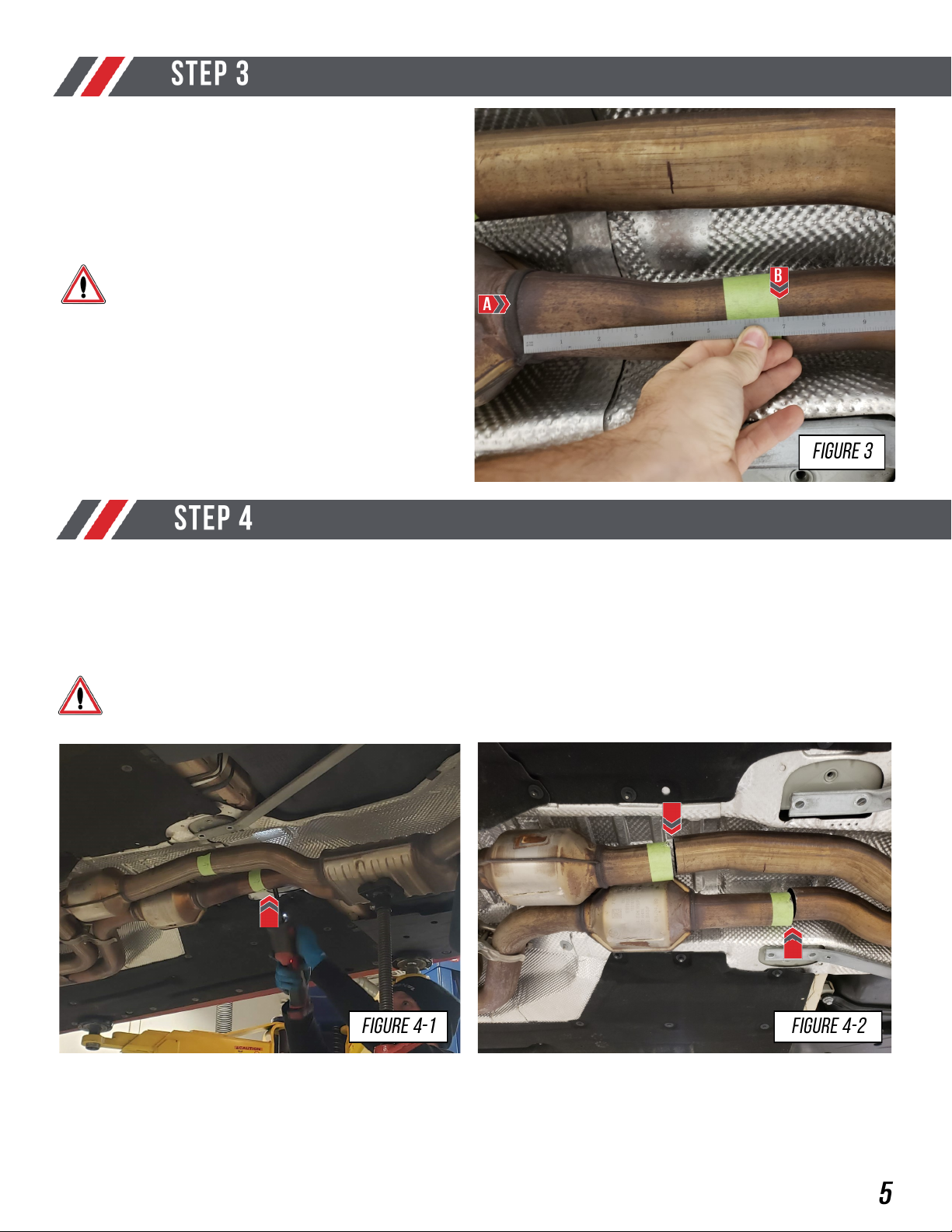
On the driver side catalytic converter measure
4.50” inches from the weld seam (A) towards
the rear of the vehicle.
Mark with tape (B) and an arrow pointing to the
rear of the vehicle, as shown in Figure 2.
It is extremely important that these
measurements are accurate as it will
effect fitment.
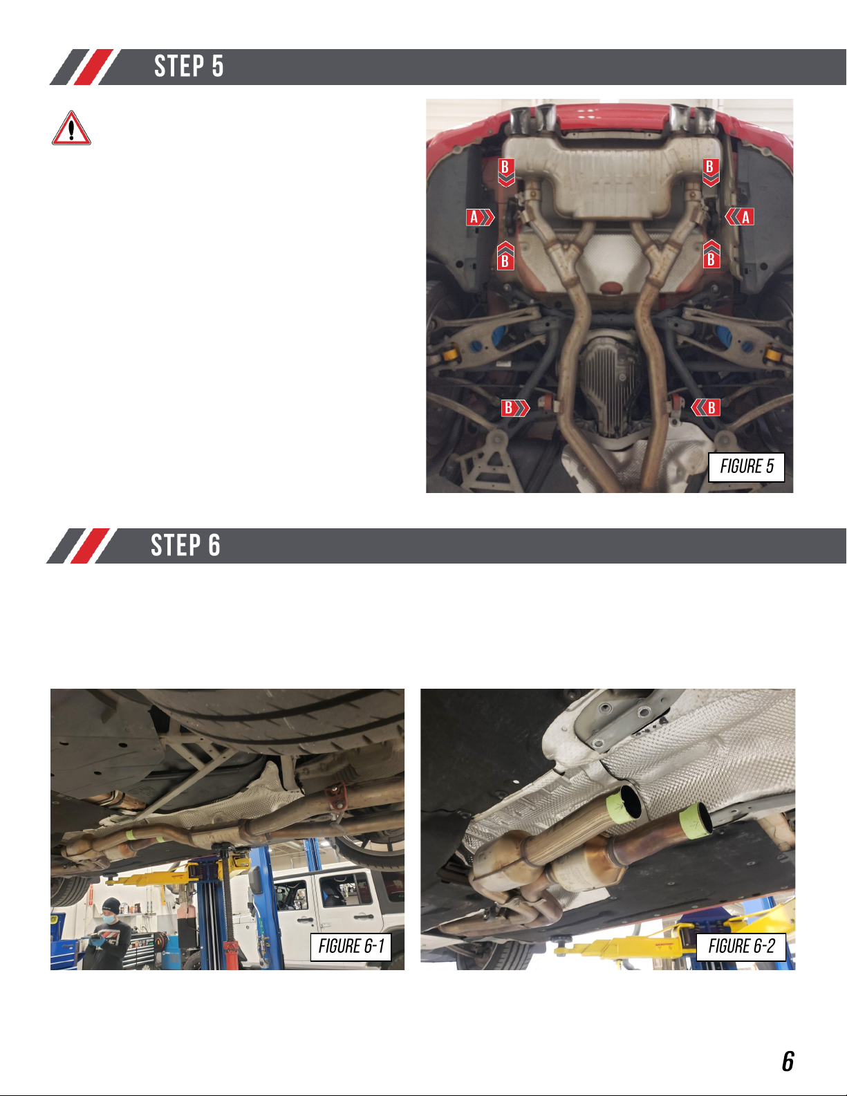
Begin by removing the OE bolts mounting the
OE chassis brace to the body, as shown in Fig-
ure 1.
Note: The OE hardware will be reused with the
install of your AWE exhaust.
COMPLETE THIS PROCESS BEFORE MOVING FORWARD
Before starting installation, the factory exhaust valves must be in the open position. Bring the en-
gine up to full operating temperature. With the engine running, press the Engine Dynamics button
to switch into Sport-Plus mode. Blip the throttle to audibly confirm the valves are open. If in doubt
of valve position, peer into the exhaust tips with a flashlight to confirm that they are open. While still
in Sport-Plus mode, shut off engine Disconnect the connectors from both valve electrical motors.
Allow exhaust to cool before proceeding with next install steps. Failure to follow this procedure
will result in the factory valve motors not aligning with the AWE Tuning exhaust valves.
Copyright 2022, AWE. No part of this document may be reused or duplicated without the express permission of AWE/Secor Ltd. All rights reserved. Rev3.7
Make a cut on the driver and passenger side exhaust tube along the rear edge of the tape, as
shown in Figure 4-1 and Figure 4-2.
NOTE: It is crucial that these cuts are accurate. Incorrect cuts will effect fitment.
Make sure that the cuts are perpendicular to the tube you are cutting.
On the passenger side catalytic converter
measure 7.00” inches from the weld seam (A)
towards the rear of the vehicle.
Mark with tape (B) and an arrow pointing to
rear of the vehicle, as shown in Figure 3.
It is extremely important that these
measurements are accurate as it will
effect fitment.
Copyright 2022, AWE. No part of this document may be reused or duplicated without the express permission of AWE/Secor Ltd. All rights reserved. Rev3.7
Unplug the 2 OE valve motors (A).
Remove the bolts mounting the 4 hangers to
the body (B), as shown in Figure 5.
Once the hangers are free, remove the OE exhaust system, as shown in Figure 6-1 and 6-2.
With your OE exhaust system removed, uninstall the OE valve motors as well as their respective
springs and bolts from the factory brackets, mark the driver and passenger and set them aside. You
will reuse them in later steps.
Before starting Step 5 ensure you have
completed the process in the note be-
fore Step 1. Failure to do this can
cause misalignment in the valve motors
Copyright 2022, AWE. No part of this document may be reused or duplicated without the express permission of AWE/Secor Ltd. All rights reserved. Rev3.7
Deburr the edges of the OE exhaust tubes you
just cut, as shown in Figure 7.
Begin installing your AWE system by, sliding
your AWE X-pipe section (D89), with the sup-
plied Accu-Seal clamps, over the cut
section, as shown in Figure 8.
Note: The OE pipe clamp just before the cats
can be loosened to help align the OE pipes and
the AWE x-pipe.
Copyright 2022, AWE. No part of this document may be reused or duplicated without the express permission of AWE/Secor Ltd. All rights reserved. Rev3.7
It is crucial to install each section and exhaust
band clamps correctly to prevent loose joints,
exhaust leaks and rattles.
Arrow A shows the expanded pipe and the
preinstalled exhaust clamp being brought up to
the corresponding pipe.
Arrow B shows the overlapping pipe installed
correctly over the corresponding pipe.
Arrow C shows the exhaust band clamp being
brought to the edge of the expanded pipe.
NOTES:
• Do not fully torque any exhaust
clamp until the entire exhaust has
been installed and adjusted.
• Torque specification is a minimum of
60 ft/lbs
Install your AWE driver side differential pipe
(D90), with the supplied Accu-Seal clamp, as
shown in Figure 10.
Copyright 2022, AWE. No part of this document may be reused or duplicated without the express permission of AWE/Secor Ltd. All rights reserved. Rev3.7
Install your AWE driver side differential pipe
(D90) using the OE hanger removed earlier, as
shown in Figure 11.
Install your AWE passenger differential pipe
(D91), with the supplied Accu-Seal clamp (A),
as shown in Figure 12.
NOTE: Reinstall the passenger side hanger (B)
removed earlier.
Copyright 2022, AWE. No part of this document may be reused or duplicated without the express permission of AWE/Secor Ltd. All rights reserved. Rev3.7
IF INSTALLLING AWE TRACK EDITION SYSTEM, SKIP TO STEP 19.
Install the provided valve spring (A) onto your
OE valve, as shown in Figure 13-1.
Next install the OE valve motor (B), as shown
in Figure 13-2.
Last check to make sure the valve motor and
spring are sitting (C), as shown in Figure 13-3.
Repeat this process for your AWE valve section,
on the driver side (D92).
Copyright 2022, AWE. No part of this document may be reused or duplicated without the express permission of AWE/Secor Ltd. All rights reserved. Rev3.7
Install your AWE valve sections (D92 and D93), with the supplied Accu-Seal clamp, onto your AWE
muffler assembly (D94), as shown in Figure 14-1 and 14-2.
Attach the OE rear hangers on both sides of
your AWE rear muffler, as shown in Figure 15.
Install your AWE muffler assembly (D92/D93/D94), with the supplied Accu-Seal clamps, onto the
AWE differential pipes, as shown in Figure 16-1 and Figure 16-2.
Copyright 2022, AWE. No part of this document may be reused or duplicated without the express permission of AWE/Secor Ltd. All rights reserved. Rev3.7
Reinstall the hardware into the OE rear
hangers (A), as shown in Figure 17-1.
Plug the OE connector into the valve motor,
shown by (B).
Note: Unclip to OE harness from the chassis
on both the driver and passenger sides to al-
low the harness to reach the AWE pipes, as
shown in Figure 17-2 and 17-3.
Note: Do so on both the driver and passenger
side.
AWE SWITCHPATH SYSTEM, SKIP TO STEP 25.
For the rear sections, hanger bar collar clamps
are provided to prevent side to side movement
of the exhaust system. After sliding the exhaust
hanger bar through the OEM grommet, install
the collar clamp on the outside end of the bar
as shown in Figure 18.
Copyright 2022, AWE. No part of this document may be reused or duplicated without the express permission of AWE/Secor Ltd. All rights reserved. Rev3.7
AWE Track System ONLY.
Install your AWE Track rear assembly (D95),
with the supplied Accu-Seal clamps and OE
hangers, onto the AWE differential pipes, as
shown in Figure 19.
NOTE: Wait to install exhaust tips, until later in
your installation.
Reinstall the OE rear hangers, as shown in
Figure 20, on both the driver and passenger
side.
For the rear sections, hanger bar collar clamps
are provided to prevent side to side movement
of the exhaust system. After sliding the exhaust
hanger bar through the OEM grommet, install
the collar clamp on the outside end of the bar
as shown in Figure 21.
Copyright 2022, AWE. No part of this document may be reused or duplicated without the express permission of AWE/Secor Ltd. All rights reserved. Rev3.7
Attach your OE valve motor to the AWE valve
motor simulator bracket.
Start by installing the dowel pin, as shown in
Figure 22-1.
Next install the OE valve motor on the simulator
bracket, keeping the dowel aligned, as shown in
Figure 22-2.
Last install the OE bolts removed earlier, as
shown in Figure 22-3.
Copyright 2022, AWE. No part of this document may be reused or duplicated without the express permission of AWE/Secor Ltd. All rights reserved. Rev3.7
With the valve motor simulators assembled,
plug them into the OE connection on the driver
side before tucking them into a pocket in the
body, as shown in Figure 23.
Plug one of your valve motors into the OE connection on the passenger side before tucking it
behind the heat shield in the bumper, as shown in Figure 24-1 and Figure 24-2.
Install your AWE chassis brace, using the OE
hardware, as shown in Figure 28.
Ensure you have torqued down the 2
clamps connecting your new AWE
system to the OE tubes before this step.
Copyright 2022, AWE. No part of this document may be reused or duplicated without the express permission of AWE/Secor Ltd. All rights reserved. Rev3.7
With all AWE exhaust components installed, go
ahead and torque down the clamps on the
entire system, working from the front of the car
to the exhaust tips.
Install all 4 AWE exhaust tips and hardware on-
to the tip outlets, as shown in Figure 26.
Note: Only snug clamps at this time.
To install the exhaust tips with integrated
clamps, first, attach the exhaust tip in the
proper orientation onto the exhaust outlet tube.
Insert one of the carriage bolts from the
hardware kit (3910-41010) through the tab on
the exhaust tip and thread on one of the
corresponding nuts.
Copyright 2022, AWE. No part of this document may be reused or duplicated without the express permission of AWE/Secor Ltd. All rights reserved. Rev3.7
Once installed properly, your AWE exhaust will provide years of trouble-free performance.
The exhaust volume and sound will settle with usage; 800-1000 miles is required to break-in new
exhaust systems.
Also, please note that the rear 180Technology® resonator has a small drain hole to allow
condensation to escape. Water drops from this area are normal.
Periodic cleaning of exhaust tips is necessary to maintain proper finish, especially in areas prone to
road salt and caustic deicing solutions. Use a mild soap and water solution or car wax to clean the
finish. Avoid using abrasive polishes, as they can scratch the finish.
Up-to-date warranty information is found HERE.
Any questions or comments,
please do not hesitate to contact us:
AWE
215-658-1670
CONTACT FORM
Issue Solution
Exhaust is not fitting correctly Most fitment issues are due to improperly adjusted exhaust.
This includes tip fitments and rattling due to chassis contact.
Check out our fitment guide for more installation tips.
Wrong or missing parts Double check the parts list for your system and compare them
with what you received. Fill out our contact form, found below
and let us know what parts you need.

This manual suits for next models

3

Other AWE Automobile Accessories manuals

AWE 2660-15060 User manual

AWE

AWE 2660-15060 User manual

AWE 3020-42080 User manual

AWE

AWE 3020-42080 User manual

AWE 3015-42201 User manual

AWE

AWE 3015-42201 User manual

Popular Automobile Accessories manuals by other brands

Westfalia Automotive AD65U Installation and operating instructions

Westfalia Automotive

Westfalia Automotive AD65U Installation and operating instructions

Seizmik 08072 Installation & operation manual

Seizmik

Seizmik 08072 Installation & operation manual

Citadel TouchStar TS3000 user manual

Citadel

Citadel TouchStar TS3000 user manual

Webasto Thermo Top E Installation documentation

Webasto

Webasto Thermo Top E Installation documentation

Parrot Minikit+ user guide

Parrot

Parrot Minikit+ user guide

travall TDG 1602 FITTING INSTRUCTION

travall

travall TDG 1602 FITTING INSTRUCTION

KW automotive W166 instruction manual

KW automotive

KW automotive W166 instruction manual

Yakima LOCKN'LOAD 8000350 manual

Yakima

Yakima LOCKN'LOAD 8000350 manual

r.LiNK RL3-UCON8-LV manual

r.LiNK

r.LiNK RL3-UCON8-LV manual

Audiovox 50-0312x SERIES installation instructions

Audiovox

Audiovox 50-0312x SERIES installation instructions

dirna Bergstrom Bycool Green Line Slimfit Mounting instructions

dirna Bergstrom

dirna Bergstrom Bycool Green Line Slimfit Mounting instructions

BeltUpp Straight Up Safety FITTING INSTRUCTION

BeltUpp

BeltUpp Straight Up Safety FITTING INSTRUCTION

Thule Motion XT 6292 instructions

Thule

Thule Motion XT 6292 instructions

Movon MDAS-9 Installation Guide book

Movon

Movon MDAS-9 Installation Guide book

Kuda 046290 Installation instruction

Kuda

Kuda 046290 Installation instruction

Mont Blanc LOGAN 2 quick guide

Mont Blanc

Mont Blanc LOGAN 2 quick guide

Connects2 CAM-MB14 user manual

Connects2

Connects2 CAM-MB14 user manual

Whispbar K489W Fitting instructions

Whispbar

Whispbar K489W Fitting instructions

manuals.online logo
manuals.online logoBrands
  • About & Mission
  • Contact us
  • Privacy Policy
  • Terms and Conditions

Copyright 2025 Manuals.Online. All Rights Reserved.