AWPLC AWGTY-DGOISG86A0 User manual

Revisão: 02
Data de Criação: 00.00.0000
Data de revisão: 24.01.2019
1
AWPLC GATEWAY MANUAL
MODEL: AWGTY-DGOISG86A0

Revisão: 02
Data de Criação: 00.00.0000
Data de revisão: 24.01.2019
1
AWPLC
The information in this manual is subject to change, on account of development,
causing changes in the product or its operation, without prior notice. If there is any
conflict between the standards in this manual and the product, please visit our website
and download the updated manual or contact our technical support.
The AWPLC manual was developed with the intuition to make the maintenance and
operational process of the equipment the smoothest and easiest as possible.
AWPLC communication is made through a radio frequency module with long-range
and high resistance to outside interferences. They are commonly used in industrial
environment to control the most various types of equipment.
The radio frequency modules are encrypted with 128 bits, making the
communication network between modules intransposible to other devices, being them
made by a third party or even by the same manufacturer, once they don't have the same
encryption code of the referred network.
All efforts were made to ensure the accuracy in the data presented on this document.
The company takes no responsibility for errors done on the printing process of this
document by a third party.
The products comprehended in this document, as well as its integrating parts,
incorporate the right protections of the manufacturer company property.
Department:
Research and Development Engineering
AWPLC
www.awplc.com.br
Todos os direitos reservados.

Revisão: 02
Data de Criação: 00.00.0000
Data de revisão: 24.01.2019
2
SUMMARY
SUMMARY ............................................................................................................. 2!
IMAGE INDEX ....................................................................................................... 3!
1.!KNOWING YOUR DEVICE .......................................................................... 4!
1.1!GENERAL VIEW ................................................................................... 4!
1.2!INTERFACES ......................................................................................... 4!
1.3!FRONTAL PANEL LEDS ...................................................................... 6!
1.4!TECHNICAL SPECIFICATION – OVERVIEW ................................... 8!
2.!SETUP AND OPERATING ............................................................................ 9!
2.1!LOGIN ..................................................................................................... 9!
2.2!USER ..................................................................................................... 10!
2.2.1!NEW USER .................................................................................... 10!
2.3!DEVICES ............................................................................................... 11!
2.3.1!NEW DEVICES ............................................................................. 12!
2.3.2!IMPORTING DEVICES ................................................................ 14!
2.4!RADIO ................................................................................................... 14!
2.4.1!RAdio SETUP ................................................................................ 14!
2.5!NETWORK ............................................................................................ 15!
2.5.1!ETHERNET NETWORK SETUP ................................................. 15!
2.5.2!WI-FI NETWORK SETUP ............................................................ 19!
2.6!BACKUP/RESTORE ............................................................................ 23!

Revisão: 02
Data de Criação: 00.00.0000
Data de revisão: 24.01.2019
3
IMAGE INDEX
Figure 1 - Perspective of AWPLC Gateway .................................................................. 4!
Figure 2 - Interfaces of AWPLC Gateway .................................................................... 5!
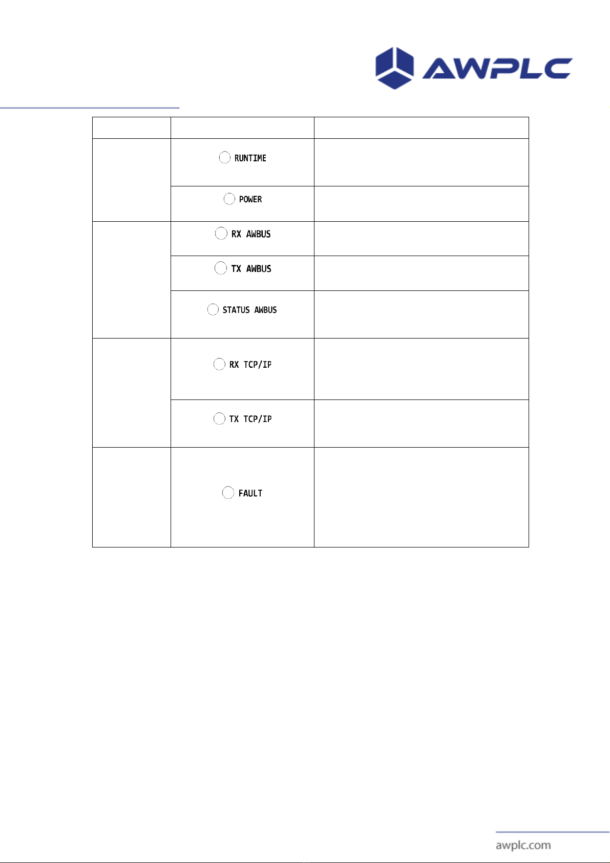
Figure 3 - AWPLC Gateway LED Panel. ...................................................................... 6!
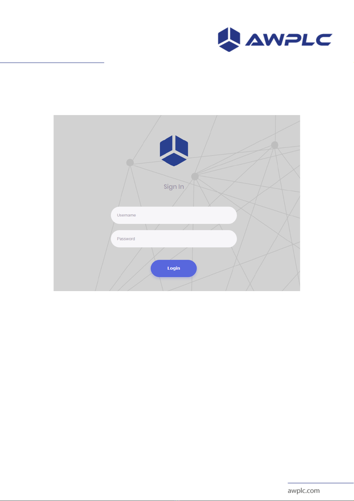
Figure 4 – Login Screen ................................................................................................. 9!
Figure 5 - Initial Screen. .............................................................................................. 10!
Figure 6 – User’s Screen .............................................................................................. 10!
Figure 7 – User’s edit and delete buttons ..................................................................... 10!
Figure 8 – New User Screen ........................................................................................ 11!
Figure 9 – Devices Screen ........................................................................................... 11!
Figure 10 - Devices ...................................................................................................... 11!
Figure 11 - Edit devices. .............................................................................................. 12!
Figure 12 - Public Objects ........................................................................................... 12!
Figure 13 - New device. ............................................................................................... 13!
Figure 14 - Add Public objects .................................................................................... 13!
Figure 15 - Import devices. .......................................................................................... 14!
Figure 16 - Import Publics Objects. ............................................................................. 14!
Figure 17 - Screen of radio. ......................................................................................... 15!
Figure 18 – Network Screen ........................................................................................ 15!
Figure 19 - Mode of ethernet operations. ..................................................................... 16!
Figure 20 - Mode Ethernet DHCP Server .................................................................... 17!
Figure 21 - Static ethernet mode .................................................................................. 18!
Figure 22 - Dynamic ethernet mode ............................................................................ 18!
Figure 23 - Default ethernet mode. .............................................................................. 18!
Figure 24 - Mode operation Wi-Fi. .............................................................................. 19!
Figure 25 - Mode Wi-Fi DHCP Server. ....................................................................... 21!
Figure 26 – Mode Wi-Fi Static. ................................................................................... 22!
Figure 27 – Mode Wi-Fi Dynamic. .............................................................................. 22!
Figure 28 - Mode Wi-Fi disable. .................................................................................. 23!
Figure 29 - Mode Wi-Fi Default. ................................................................................. 23!
Figure 30 - Backup/Restore Screen. ............................................................................ 23!
Figure 31 - Message of security. .................................................................................. 24!

Revisão: 02
Data de Criação: 00.00.0000
Data de revisão: 24.01.2019
4
1. KNOWING YOUR DEVICE
1.1 GENERAL VIEW
Figure 1 - Perspective of AWPLC Gateway
1.2 INTERFACES

Revisão: 02
Data de Criação: 00.00.0000
Data de revisão: 24.01.2019
5
Figure 2 - Interfaces of AWPLC Gateway
ITEM
DESCRIPTION
1
Frontal Panel and LED indicators. The functionality of any LED indicator will be discussed
futhermore.
2
Power Plug. Connect a 5.2VDC/15.6W power supply using an P4 Jack to Power On your
device. Attention to polarity show in marking! This device has no Polarity Inversion
Protection!
3
SMA Antenna connector. Used to AWBUS radio module.
4
AWPLC Gateway information (Model and Serial Number).
5
USB connector. Those connectors have a reserved function. Future applications may be
provided to interconnection with other AWPLC modules. Do Not connect any type of
device to those connectors!
6
Ethernet Connector. Used for MODBUS over TCP/IP connection.

Revisão: 02
Data de Criação: 00.00.0000
Data de revisão: 24.01.2019
6
1.3 FRONTAL PANEL LEDS
Figure 3 - AWPLC Gateway LED Panel.
The frontal panel of AWPLC GATEWAY has 8 LEDs indicators. Their functions
are better explained in table below.

Revisão: 02
Data de Criação: 00.00.0000
Data de revisão: 24.01.2019
7
Main Group
Figure
Description
AWPLC
GATEWAY
Operation
The RUNTIME LED blinks if the AWPLC is
running normally. It remains off at the
initialization time and in case of Fail Conditions.
The POWER indicators remains on if the MPU is
energized and the AWPLC is ready to run.
AWBUS
The RX AWBUS LED blinks whenever the radio
receive a valid data package.
The TX AWBUS LED blinks whenever the radio
transmit a data package.
The STATUS AWBUS LED blinks to indicate
network association. If the LED remains off, then
no network association was made.
TCP/IP
The RX TCP/IP LED blinks whenever the
Ethernet Module receive a data package over
TCP/IP protocol that must be processed by
runtime.
The TX TCP/IP LED blinks whenever the
Ethernet Module transmit a data package over
TCP/IP processed by runtime.
FAULT
CONDITION
This LED FAULT turns on during any fault
condition except for Processing Unity fault. For
this last exception, after the initialization
sequence, if the RUNTIME LED does not blink
and the FAULT LED remains off, then the user
may conclude that there is a Processing Unity
Fault condition.

Revisão: 02
Data de Criação: 00.00.0000
Data de revisão: 24.01.2019
8
1.4 TECHNICAL SPECIFICATION – OVERVIEW
PHYSICAL
Characteristic
Symbol
Min
Typical
Max
Unity
Length
L
85.4
85.5
85.8
mm
Width
W
125.0
125.25
125.4
mm
Height
H
46.9
47.0
47.2
mm
Weight
Wt
-
-
-
g
Degree Protection
-
IP40
-
-
CLIMATIC CONDITIONS
Characteristic
Symbol
Min
Typical
Max
Unity
Operating temperature
5
-
55
°C
Storage temperature
-40
-
70
°C
Relative humidity
10
-
95
%
ELECTRICAL
Characteristic
Symbol
Min.
Typical
Max.
Unity
PLC Power
Supply
Incoming
Voltage
UePLC
5.0
5.2
5.5
V DC
Current
Consumption
(@ UePLC=5.2VDC)
IePLC
250
300
1000
mA
Power Supply Insulation
-
-
NONE
-
kV
-
RF SYSTEM
Characteristic
Symbol
Min.
Typical
Max.
Unity
Radio Frequency Band
-
863
868
870
MHz
Transmit Power
-
-
-
13
dB
Data Rate
-
-
-
250
kBps

Revisão: 02
Data de Criação: 00.00.0000
Data de revisão: 24.01.2019
9
2. SETUP AND OPERATING
2.1 LOGIN
Gateway’s login screen:
Figure 4 – Login Screen
After the login process you will be redirected to the main menu screen of the
Gateway.

Revisão: 02
Data de Criação: 00.00.0000
Data de revisão: 24.01.2019
10
Figure 5 - Initial Screen.
2.2 USER
Clicking on the user menu you will initially list all the existing users registered
to access the Gateway. New users can be added by clicking on the new button on
the right side of the screen.
Figure 6 – User’s Screen
It is also possible to change the name and password of the user clicking on the
Edit button (Image 4). If necessary it is also possible to delete a user by clicking the
existing Delete button.
.
Figure 7 – User’s edit and delete buttons
2.2.1 NEW USER

Revisão: 02
Data de Criação: 00.00.0000
Data de revisão: 24.01.2019
11
After clicking on the New User button:
Figure 8 – New User Screen
Fill in all the data and press Save. A new user will be added on the list of users.
2.3 DEVICES
Devices screen:
Figure 9 – Devices Screen
On this screen it is possible to see the options the Edit or Delete at the right
side of the screen, or even add or import new devices through the New or Import
buttons on the right superior corner.
Figure 10 - Devices

Revisão: 02
Data de Criação: 00.00.0000
Data de revisão: 24.01.2019
12
By clicking on the Edit button, you can change the name, address or even
disable the device as seen in image below:
Figure 11 - Edit devices.
It is also possible to see all the Public Objects of the Parameters and Status
attached to the device as the image below:
Figure 12 - Public Objects
2.3.1 NEW DEVICES
To add a new device simply click on the New button on the Device Screen and
you will be directed to the screen as seen in image below:

Revisão: 02
Data de Criação: 00.00.0000
Data de revisão: 24.01.2019
13
Figure 13 - New device.
Please fill out all the fields. The Address field accepts numeric values from
1 to 247. To add a Public Object on Status or Parameters, simply click on the desired
tab followed by the Add button.
After thtat the fields contained on the image 11 will be shown. The Public
Objects Address field on the Status Tab allows numeric values between 10000 to
11023, and the Parameters field numeric values from 1 to 1024.
Figure 14 - Add Public objects
Fill out the Name filed and on Type select the suitable Public Object. Stay
alert to Type field as the Public Object with the Type REAL, DWORD, UDINT e
DINT takes two address positions. With the STRING type the size is just one as
seen in the Size field.
The Size field is enable just for Public Objects with the STRING type
assigned and it is suitable to define the occupied size on the address attribute. The
Enable option is used to switch the state of the Public Object.
The Public Objects can be readable or writable. If you want to choose the
readable option simply mark the Readonly option.

Revisão: 02
Data de Criação: 00.00.0000
Data de revisão: 24.01.2019
14
2.3.2 IMPORTING DEVICES
To make the importing process, simply click on the Import Button on the Devices
Screen and select the AWBUS.conf file generated by the AWPLC Studio.
Figure 15 - Import devices.
It is also possible to import the Public Objects to a already existing device. For
that click on the Edit button on the device you want to make the change and after that
click on the Import button as seen on the Image 13. Select the AWBUS.conf
generated by the AWPLC Studio all you are all set.
Figure 16 - Import Publics Objects.
In both cases if you select a valid file a message will be shown saying that the
importing process was completed. Click on OK and the page will be updated.
2.4 RADIO
On this screen you can define the Radio’s address and name.
2.4.1 RADIO SETUP
The Address field accepts numeric values from 1 to 247 and the Name filed
values from 3 to 20 characters.

Revisão: 02
Data de Criação: 00.00.0000
Data de revisão: 24.01.2019
15
Figure 17 - Screen of radio.
Click on Save button to update the informations.
2.5 NETWORK
On the Network Screen there is two Tabs (Ethernet and Wi-Fi), both are suited to
define the parameters for this two kind of communication of the Gateway. The Tabs
are shown on the image below:
Figure 18 – Network Screen
On the Ethernet operational mode there is the following options: DHCP
Server, Static IP, Dynamic and Default.
On the Wi-Fi operational mode the options are: DHCP Server, Static IP,
Dynamic, Disabled and Default.
2.5.1 ETHERNET NETWORK SETUP
The Ethernet configuration tab is used for selection of the operational mode of
the Ethernet interface.
As was said previously the operational modes are DHCP Server, Static IP,
Dynamic and Default as seen on the image below:

Revisão: 02
Data de Criação: 00.00.0000
Data de revisão: 24.01.2019
16
Figure 19 - Mode of ethernet operations.
Each one of the operational mode enables a set of fields that must be filled out
correctly. Below are the explanations of each one of those necessary fields:
• IP Address: Corresponds to the network address used by the Gateway itself.
.
• Netmask: It is a 32 bits responsable to separate the network mas and it also
separes the node number. (I.E. for a common address like 192.168.0.X the
netmask is 255.255.255.0 as used on a computer network).
.
• Start IP Address: It is used to mark the initial number of the network address
range for the devices receiving address from the DHCP Server mode (it can
receive numeric values from 0 to 253).
.
• Final IP Address: It is used to mark the last number of the network address
range for the devices receiving address from the DHCP Server mode (it’s
maximum value is 254).
• Gateway: Used to define to the network interface where the packages must
pass in case of an Internet Connection. Normally used to define the DNS
resolver address. (*DNS resolver equals “DNS Lookup” - resolves and
individual host name to a Public IP address).
• Primary DNS: The first option for DNS resolver. (I.E. a normally used
address for Primary DNS is the Google Primary DNS address 8.8.8.8. Another
option is OpenDNS 208.67.222.222).
• Secondary DNS: The second option for DNS resolver. (I.E. a normally used
address for Primary DNS is the Google Secondary DNS address 8.8.4.4.
Another option is OpenDNS 208.67.220.220).

Revisão: 02
Data de Criação: 00.00.0000
Data de revisão: 24.01.2019
17
On the DHCP Server mode, the gateway will be responsible for managing all
the connected devices on this network. Here comes a very important WARNING,
the Highlander rule. DHCP Server devices are like Highlanders, “there can be
only one” on each network. If you set two or more DHCP Servers on the same
network, they will be fighting for the management of the devices and this can
generate a real mess on your whole network.
**Highlander = An immortal character from a 1986 movie (and also a 1992-1998 Serie), that fights against other
immortals until death. Highlanders assume the killed highlander’s powers, so the battle just ends when there’s
only one left.
The fields Address IP, Netmask, Start IP and Final IP must be filled as
explained before. See the image below with an example:
Figure 20 - Mode Ethernet DHCP Server
On the Static IP mode the fields Address IP, Netmask, Start IP and Final IP
must be filled as explained before. See the image below with an example:

Revisão: 02
Data de Criação: 00.00.0000
Data de revisão: 24.01.2019
18
Figure 21 - Static ethernet mode
On the Dynamic mode there’s nothing to be done, since all the configurations
are received from a DHCP Server:
Figure 22 - Dynamic ethernet mode
The Default mode is a DHCP Server mode with default values. The IP will
be set as 1.0.0.1. Those are values determined by us, just to make sure they are
different from the ones commonly used on computer networks and are able to not
generate some kind of conflict. Remember the Highlanders rule. J
Figure 23 - Default ethernet mode.

Revisão: 02
Data de Criação: 00.00.0000
Data de revisão: 24.01.2019
19
2.5.2 WI-FI NETWORK SETUP
The Wi-Fi setup Tab is used to configure the operational mode of the Wi-Fi
interface that exists on the Gateway. The parameters here are: IP Address, Netmask,
Gateway, DNS, SSID, Password, Start IP and Final IP.
On the current version of the AWPLC there are 5 different operational modes
for the Wi-Fi interface: DHCP Server, Static IP, Dynamic IP, Disabled and Default,
as shown on the image below:
:
Figure 24 - Mode operation Wi-Fi.
Each one of the operational mode enables a set of fields that must be filled out
correctly. Below are the explanations of each one of those necessary fields:
• IP Address: Corresponds to the network address used by the Gateway itself.
.
• Netmask: It is a 32 bits responsable to separate the network mas and it also
separes the node number. (I.E. for a common address like 192.168.0.X the
netmask is 255.255.255.0 as used on a computer network).
.
• Start IP Address: It is used to mark the initial number of the network address
range for the devices receiving address from the DHCP Server mode (it can
receive numeric values from 0 to 253).
.
• Final IP Address: It is used to mark the last number of the network address
range for the devices receiving address from the DHCP Server mode (it’s
maximum value is 254).
• Gateway: Used to define to the network interface where the packages must
pass in case of an Internet Connection. Normally used to define the DNS
Table of contents