AWS AIRBAR User manual

1
OPERATOR’S MANUAL
AWS Airbar Systems
(Header Mount Fan)
Version: 20200325


AWS AirBar Operator’s Manual
INTRODUCTION ........................................................................................... 1
FOREWORD...........................................................................................................................1
ITEMS INCLUDED WITH AIRBAR KITS......................................................................................1
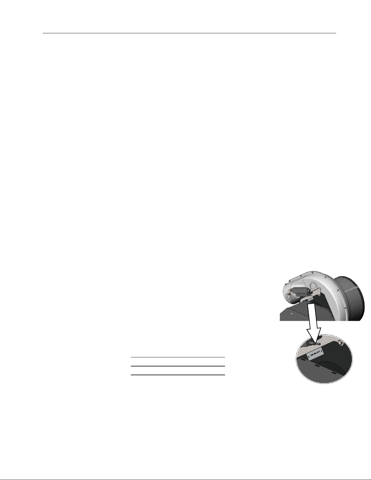
SERIAL NUMBER LOCATION...................................................................................................1
REPLACEMENT PARTS INFORMATION....................................................................................1
UNAUTHORIZED MODIFICAITON ...........................................................................................2
MISUSE OF EQUIPMENT ........................................................................................................2
PRODUCT DESIGN .................................................................................................................2
OFFICIAL LANGUAGE .............................................................................................................2
COMPONENT IDENTIFICATION................................................................... 3
SAFETY ........................................................................................................ 4
SAFETY ALERT SYMBOL..........................................................................................................4
HAZARD SERIOUSNESS LEVEL.................................................................................................4
GENERAL SAFETY PRECAUTIONS............................................................................................4
POWER UNIT SAFETY.............................................................................................................5
OPERATING EQUIPMENT SAFELY ...........................................................................................5
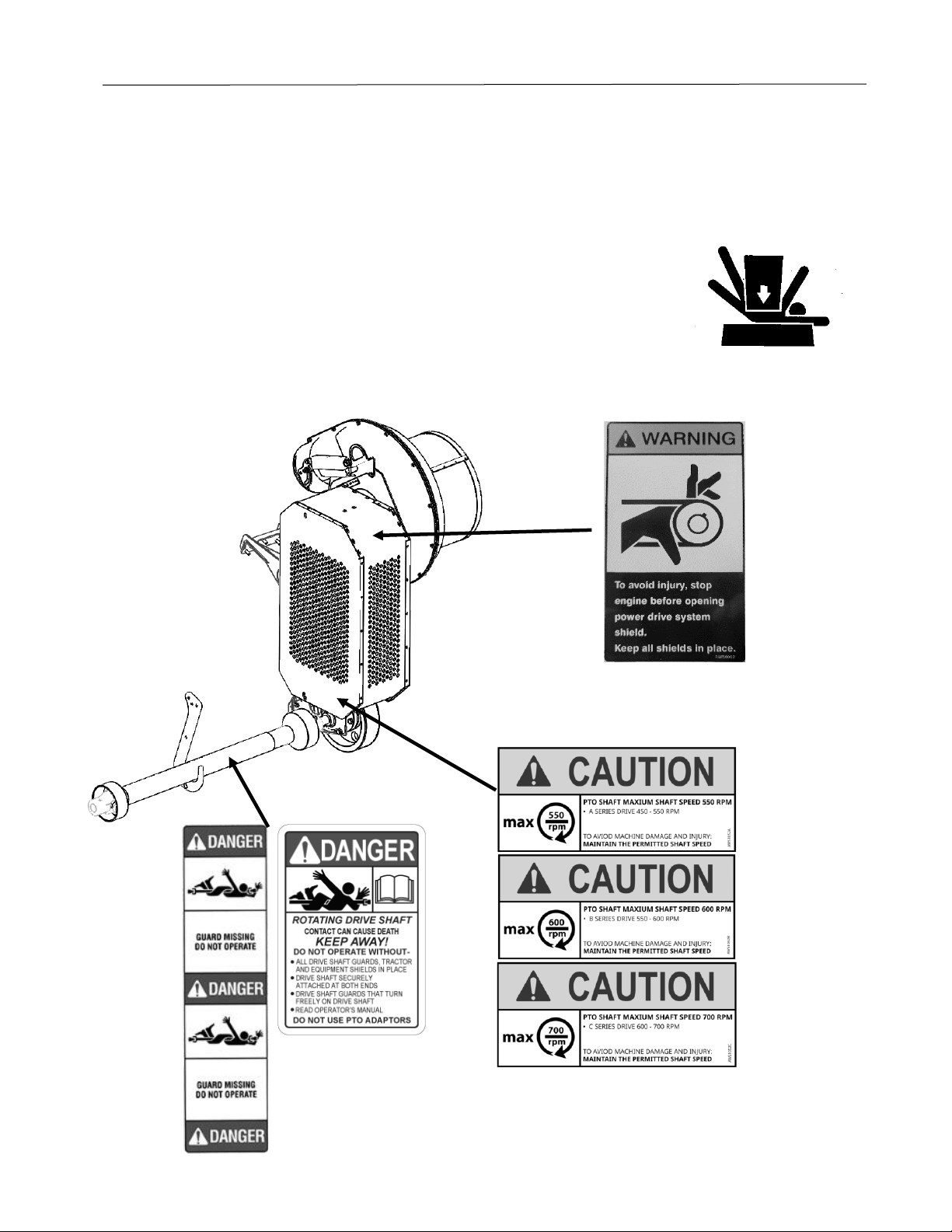
SAFETY DECALS .....................................................................................................................6
SYSTEM SETUP FOR OPERATION .............................................................. 7
WHEN CONNECTING THE HEADER..........................................................................................7
WHEN DISCONNECTING THE HEADER.....................................................................................7
OPERATING THE SYSTEM .......................................................................... 8
DAILY CHECKS .......................................................................................................................8
REEL POSITION......................................................................................................................8
MANIFOLD HEIGHT ADJUSTMENT..........................................................................................8
ELECTRICAL CONTROLS..........................................................................................................8
NOZZLE ROTATION ADJUSTMENT ..........................................................................................9
AIR FLOW ADJUSTMENT......................................................................................................10
MAINTENANCE .......................................................................................... 10
LUBRICATION...................................................................................................................... 11
NOZZLE INSPECTION............................................................................................................ 12
BELT /SHEAVE /IDLER CONDITION ...................................................................................... 13
BELT TENSION ..................................................................................................................... 13
BEARING SERVICE................................................................................................................14
BELT SERVICE ...................................................................................................................... 14
BLOWER INSPECTION .......................................................................................................... 15
ROTARY SCREEN.................................................................................................................. 15
MANIFOLD /AIR DUCTING...................................................................................................15
FASTENER TORQUE .............................................................................................................16


AWS AirBar Operator’s Manual
1
INTRODUCTION
Thank you for purchasing an AWS AirBar system. This product is designed and manufactured
to allow for safe operation while increasing the productivity of your harvesting operation. A
well-maintained system will provide years of reliable service.
FOREWORD
Keep this manual with the system at all times. This manual is intended as a guide to the safe
use and maintenance of the system. Before you head to the field, study this manual carefully.
Replace this manual immediately if it becomes lost.
AWS AirBar systems are an air-assist tool to increase the productivity and efficiency of your
auger or draper style combine header. This system is customized to fit your head / combine
combination. The air blast provided by the system improve crop in-flow past the knife and
reduce shatter related losses at the knife.
Features:
•Belt driven fan, powered from the combine header drive system.
•Optimized nozzle configurations (based on reel design)
•Adjustable air flow and nozzle position
•In-cab adjustment controls
Applications:
•Dry Beans
•Soybeans
•Lentils
•Peas
•Cereals
ITEMS INCLUDED WITH AIRBAR KITS
•Operator’s Manual
•Installation Manual
SERIAL NUMBER LOCATION
The serial number plate for the system is located on the fan housing plate.
For quick reference, record the following information:
Header Model: __________________________
Serial Number: __________________________
Date Purchased: __________________________
REPLACEMENT PARTS INFORMATION
Use only genuine Original Equipment Manufacturer’s (O.E.M.) replacement parts. The use of
“will fit” parts may reduce system performance, void manufacturer’s warranty and present a
safety hazard. Use only genuine O.E.M. replacement parts.

AWS AirBar Operator’s Manual
2
UNAUTHORIZED MODIFICAITON
Modifications to the original design of the AirBar system, including the use of unauthorized
accessories or non-genuine OEM parts, may affect the reliability of the system or make it
unstable or unsafe to operate and perform as originally designed and intended. Persons or
organizations that make unapproved modifications (including operation without provided
guards and shields) assume all liability arising from or related to the modification including
any adverse affect on the system.
No modification can be made to the original design or assembly of the Air-Bar system
(including any and all attachments, safety or control devices) without the prior written
consent of TEMP Farm Equipment (see contact information below). TEMP Farm Equipment
Ltd. retains the right to reject all claims which arise from or are related to unauthorized
modifications.
MISUSE OF EQUIPMENT
It is incumbent upon the user, owner and selling dealer of this equipment along with their
respective employees to warn and discourage users about the misuse of the equipment
whenever knowledge of misuse becomes known, whether the act has, is or could occur. Such
acts include, but not limited to: riding upon, use of non-OEM parts, operating in fire-hazard
areas, modifications that alter the original system specifications or use other than originally
intended, etc.
PRODUCT DESIGN
If any person, employee, agent, dealer or distributor becomes aware of any Unauthorized
Modification or Misuse of an AWS AirBar system, either past or intended, it is the
responsibility of that person to ensure that TEMP Farm Equipment is notified of the
occurrence promptly. That person shall provide; the facts of the occurrence, location, system
serial number, name and contact information of the persons involved.
Send correspondence regarding Unauthorized Modification or Misuse to:
TEMP Farm Equipment
3890 Wellington St.
Mitchell, Ontario, N0K 1N0
Canada
OFFICIAL LANGUAGE
No responsibility is assumed for translations in other languages, which do not correspond to
the original meaning. Under our policy of continuous improvement, we reserve the right to
change specifications and designs without prior notice. The illustrations shown do not
necessarily represent the standard version of product offered by TEMP Farm Equipment Ltd.

AWS AirBar Operator’s Manual
3
COMPONENT IDENTIFICATION
END CAP
NOZZLES
MANIFOLD
LOCK SLEEVE
TRANSITION
TUBE
MOUNT ARM
BRACKET
MOUNT ARM
BRACKET
BLOWER
ASSEMBLY
Figure 1 –View ‘A’
ROTARY
SCREEN
THROTTLE
/W ACTUATOR
BELT
DRIVE
INPUT PTO
SHAFT
/W STORAGE HANGER
Figure 3 –Manifold Tilt Mechanism –1 pc Reel
MANIFOLD
TILT ACTUATOR
Figure 4 –Manifold Tilt Mechanism –Multi-piece Reel
MANIFOLD
TILT ACTUATOR
Figure 2
Control Switch Box
(Installed in Cab)
MANIFOLD
TILT CONTROL
THROTTLE
CONTROL

AWS AirBar Operator’s Manual
4
SAFETY
SAFETY ALERT SYMBOL
This symbol appears at various points in the manual together
with a signal word and warning text. It means –Be alert! Your
safety is involved. This symbol is used throughout the manual to
call attention to areas in which carelessness or failure to follow
specific procedures may result in personal injury or component
damage / malfunction or both.
HAZARD SERIOUSNESS LEVEL
The following signal words are found throughout the manual
together with the safety alert symbol to indicate the seriousness
level of identified hazards. Their selection is based on the
consequence of human interaction with a hazard.
DANGER! –Hazards or unsafe practices which WILL result in
severe personal injury or death.
WARNING! –Hazards or unsafe practices that COULD result in
severe personal injury or death.
CAUTION! –Hazards or unsafe practices that COULD result in
minor personal injury or product or property damage
GENERAL SAFETY PRECAUTIONS
The operator of this system must have sufficient knowledge and
instructions in the care and operation of this system and the
power unit being used before he / she uses the system. Do not
allow unauthorized persons or children to operate the system.
It is the obligation of the operator to make sure that all guards
and shields are in place on the system. Safety decals must be in
place and be readable –accidents may otherwise occur. Contact
your dealer or the manufacturer for replacement manuals or
decals.
• Never use a system that does not have an operator’s manual
available. Learn and understand the safety signs and symbols on
the system and the operator instructions before you begin to
use the system.
• Wear personal protective equipment. Know and use the
protective equipment that is to be worn when operating or
servicing the system. Hard hats, protective glasses and face
shields, protective shoes, gloves, reflector type vests, and ear
protection are types of equipment that may be required.
Prolonged exposure to loud noise can cause hearing damage.
DANGER!
WARNING!
CAUTION!

AWS AirBar Operator’s Manual
5
• Never operate a system while under the influence of drugs or
alcohol. These make reflexes slow and put you and others in
grave danger. Always make sure you have full concentration
while harvesting.
• Adhere strictly to all regulations at the worksite pertaining to
the operation of this equipment.
• Be prepared for emergencies. Have a first aid kit, fire
extinguisher and emergency contact information available at
the work site.
POWER UNIT SAFETY
• The operator must have sufficient knowledge in the care and
operation of the power unit (combine) before connecting power
unit to the system. Read and understand power unit operator’s
manual before connecting mower.
• Follow recommendations of power unit manufacturer. Seat
belt must be worn at all times.
• Power unit must be equipped with a PTO connection matching
the shaft supplied with the system. Never use PTO adapters to
connect implements.
OPERATING EQUIPMENT SAFELY
• Make sure PTO shaft is properly locked. If the PTO shaft comes
off during operation, personal injury or equipment damage
could result.
• Never disconnect PTO shaft at fan drive. Always disconnect at
feeder house end and stow in supplied hanger.
• Keep all bystanders well away from the machine when it is
operating. Always maintain a safe operating distance from
personnel, other equipment, or vehicles.
• Never operate the system with shields or guards removed.
• Air blast can cause small objects and debris to be blown from
the header deck at high speeds. Avoid walking behind header
with system operational.
• Never tamper with safety devices or operate the system with
them removed. Check proper operation regularly.
• Always disengage PTO, place all controls in neutral, turn power
unit off, set parking brake, and remove key before dismounting,
for any reason.
• Never place hands or feet near the system components when
the system is operating or power unit engine is running.
• Disengage the PTO and turn power unit off upon striking any

AWS AirBar Operator’s Manual
6
object. Inspect system and repair any damage before
continuing.
• If the equipment should start to vibrate abnormally during
operation, stop the system, shut down power unit, and
immediately check for the cause. Excess vibration is generally an
indication of a problem. Replace bent or damaged parts, do not
attempt to straighten a bent fan blade.
• Before disconnecting from power unit, always lower
equipment
to the ground, place controls in neutral, set park brake, turn
engine off, and wait for all moving parts to stop. Relieve
hydraulic pressure per power unit manufacturer’s instructions.
SAFETY DECALS
PN: AWS0062
PN: AWS1052A
(John Deere,
CaseIH Combines)
PN: AWS1052B
(New Holland,
Gleaner Combines)
PN: AWS1052C
(Claas Lexion Combines)
PN: AWS1053O
PN: AWS1053I

AWS AirBar Operator’s Manual
7
SYSTEM SETUP FOR OPERATION
WHEN CONNECTING THE HEADER
EACH SYSTEM IS DESIGNED SPECIFICALLY FOR THE INTENDED COMBINE TO
BE USED. DO NOT CONNECT SYSTEM TO A DIFFERENT COMBINE WITHOUT
CONSULTING TEMP FARM EQUIPMENT FOR APPROVAL. DRIVELINE
OVERSPEED COULD OCCUR
CONNECTING THE PTO
Ensure the feeder house drive splines are free debris and
covered in a light coat of grease.
Remove telescoping PTO shaft from storage hanger and connect
to feeder house shaft. Verify that the quick-attach collar fully
locks. Secure shield safety chain to feeder house.
ELECTRICAL CONNECTIONS
There is a single connection to be made between the combine
and AirBar system. Locate the 4-pin connector on the header
harness and connect to mating connector on feeder house.
WHEN DISCONNECTING THE HEADER
DISCONNECTING THE PTO
Disconnect telescoping PTO shaft from the feeder house shaft.
Place shaft in the storage hanger.
DO NOT LEAVE PTO SHAFT CONNECTED TO THE COMBINE. PERSONAL
INJURY OR MACHINE DAMAGE MAY OCCUR IF FEEDER HOUSE IS ENGAGED.
ELECTRICAL CONNECTIONS
Disconnect the 4-pin connector joining the combine to the
header. Secure both ends of the harness to avoid damage when
the system is not in use.
WARNING!
WARNING!

AWS AirBar Operator’s Manual
8
OPERATING THE SYSTEM
DAILY CHECKS
Safety Shields
In place
Rotary Screen
Rotates freely
Clear of trash
Nozzles
Properly secured to manifold
No bent / broken nozzles
Electric Controls
Throttle & manifold tilt actuators
function properly
Electrical
Connection
Plugs secured at header
Harness is secured
REEL POSITION
The use of the AirBar system aids not only in reducing shatter
loss but also the inflow of crop material, assisting the finger reel
system.
In most cases, shatter loss can be reduced further with the
ability to set the finger reel higher than if an AirBar system is not
used.
When entering the crop, begin with the reel the “normal” height
and begin to raise the reel until you see a decrease in
performance.
MANIFOLD HEIGHT ADJUSTMENT
The manifold height can be adjusted in accordance with the
desired reel position. In most applications the mid-height
adjustment hole is appropriate.
It is important that the “heel” of the nozzle (area of the bend) is
2-4” higher from the ground than the nozzle tip when in the
operating position.
ELECTRICAL CONTROLS
All nozzle and air flow adjustments for the AirBar system are
made using the electrical switch box installed in the cab.
There are 2 separate switches:
1. Air Volume (Cycles Throttle Actuator)
+ Increase Air Output
- Decrease Air Output
2. Nozzle Tilt (Cycles Manifold Tilt Actuator)
+ Tilt Nozzle toward head
- Tilt Nozzles Away from Head
1
2

AWS AirBar Operator’s Manual
9
NOZZLE ROTATION ADJUSTMENT
The most important adjustment affecting the performance of
your AirBar system is the position of the nozzles.
The nozzles should be aimed so that the air blast contacts the
head 2” – 5” behind the knife.
This position will allow for loose crop material to be swept into
the header as well as aid in lifting the crop mat into the infeed
system on the header (auger or canvas). The crop mat should
“float” on a cushion of air similar to an air-hockey puck.
Indicators of improper nozzle adjustment are:
Tilt Too Far Rearward (in)
Material bunching on knife,
excessive knife losses
Tilt Too Far Forward (out)
-System Ineffective
-Excessive Dust / Debris

AWS AirBar Operator’s Manual
10
AIR FLOW ADJUSTMENT
The AWS AirBar system is designed to be capable of providing
excess air flow in most applications. The electric throttle control
is provided to allow for optimization of the air flow regardless of
harvest conditions.
NOTICE - The use of excess air flow not only leads to increased
crop loss but also consumes excess power; leading to increased
component wear and fuel consumption.
To Adjust Air Flow:
•Position and the air throttle at the full-open position.
•Close the throttle a bit at a time, observing the crop flow
over the knife after each adjustment.
•At the point where you see the crop flow worsen, open
the throttle back up to the previous position.
•This is the most efficient setting for those conditions.
This setting should be checked periodically through the day as
well as from field to field. Plant moisture content, yield, and
plant population will affect where the throttle should be
positioned.
MAINTENANCE
Ensure the combine controls are in the park position, the engine is turned
off, head is in the parked position, the parking brake is engaged, and
hydraulic pressure has been relieved before performing service or
maintenance.
Perform all maintenance with the head in the lowered position and the
machine on a flat and level surface.
Always use personal protection devices such as protective glasses and face
shields, protective shoes, gloves, hard hats, and ear protection when
performing service or maintenance functions.
When completing a maintenance or service function, ensure all safety
shields are installed before placing system in service.
WARNING!

AWS AirBar Operator’s Manual
11
Maintenance Intervals
Service
Weekly
Annual
Inspect Nozzles
X
Grease PTO Shaft
X
Grease Bearings
X
Check / Adjust Belt Tension
X
Inspect Rotary Screen
X
Inspect Fan Impeller
X
Inspect Manifold
X
Inspect Pulleys/Sheaves
X
Inspect Bearings / Idlers
X
Inspect Framework / Fasteners
X
LUBRICATION
GREASE SPECIFICATIONS
NOTICE –All greases are not compatible. Use of incompatible
greases will decrease lubrication qualities and can cause
premature component failure
Specification: NLGI GL-2
Grease Type: Mineral Oil, Lithium Soap Thickener
Grease of this type is considered “general purpose”. It can be
used on all components of the AirBar system.
Notes:
1. Do not use “high-temperature” greases. Normal operating
conditions of this system will not exceed the recommended
temperature range of conventional grease. High-
temperature greases may use thickeners not compatible with
OEM grease.
2. Do not use “MOLY” greases (molybdenum disulphide
additives). These greases are not suitable for extended use
with rolling element bearings.
3. Do not use greases with synthetic base oils. These synthetic
components may not be compatible with OEM grease.

AWS AirBar Operator’s Manual
12
PTO SHAFT
Location A –4-6 Pumps (15 grams)
Location B –2-3 Pumps (6 grams)
Location C* –4-6 Pumps (15 grams)
*Note –Pull PTO shaft apart & apply grease to inner profile.
BEARINGS
The (4) shaft bearings are the only grease points on the main
chassis, (2) on each side.
On some 35’ and 45’ systems (equipped with an extended
driveline), there is an additional bearing that requires greasing.
NOZZLE INSPECTION
Opening
It is critical that the nozzle opening be set to 3/8”. They can
become collapsed or opened during use from contact with rocks
and other debris and wear.
To check & set the opening, a 3/8” bolt can be used. To set the
opening, insert the bolt and pinch using pliers as shown.
U-Bolt
Vibrations from normal use can cause the gasket between the
nozzle yoke & manifold to take a set, reducing tension in the U-
bolt. Check tightness of U-bolt nuts periodically using a 7/16
wrench or deep socket.
3/8”

AWS AirBar Operator’s Manual
13
BELT / SHEAVE / IDLER CONDITION
Inspect all belts, sheaves and idlers for good condition.
Belts should appear supple with no shiny appearance on the
drive surface or cracks on the inner or outer surface.
Belts should not sit in the bottom of the sheave grooves or the
inner ribs between grooves should not be worn to a point. If
either of these cases exist, the sheave is worn excessively and
should be replaced.
Idler pulleys should be in-line with the belt running path and
parallel with the sheaves. If the idler is not inline or parallel,
inspect the idler bearing condition or the bronze bushings on
which the idler pivots for wear. Replace as required.
BELT TENSION
Proper belt tension is critical to both optimum performance and
long life of your AirBar system. Loose belts will create excessive
heat and ultimately fail. Belts that are too tight can lead to
accelerated bearing failure.
Belt tension is set using a draw-bolt to extend a spring. The
extended spring maintains tension.
On initial tensioning of new belts, tighten the draw bolt until a
quarter can fit between the coils. Once initial run-in is
completed, maintain a dime-thickness gap in the spring.
It is important to set the secondary belt tension first, then the
primary. Double-check the secondary belt tension after setting
primary tension.
“Quarter”Thickness –Initial
“Dime”Thickness –Run-In
Primary Tensioner
Secondary
Tensioner

AWS AirBar Operator’s Manual
14
BEARING SERVICE
The spherical bearings used on the AirBar drive system are
secured to the shafts using eccentric locking collars.
NOTE –Always apply anti-seize compound to shaft before
mounting bearing.
To secure the collars:
•Slide the eccentric collar against the mating end of the
insert inner race.
•Snug the collar on the mating eccentric in the direction of
shaft rotation.
•Place a mild steel bar inside the hole provided by the collar
and tap the collar sharply in the direction of shaft rotation
and perpendicular to the shaft
•Tighten the setscrew in the collar to the proper torque (156
in-lb)
•Re-check tightness of the setscrew and hold down bolts
after 24 hours of operation to insure nothing has loosened.
To remove the collar
•Loosen the setscrew, then tap the collar in the direction
opposite the shaft rotation.
BELT SERVICE
From 2021, all AWS AirBar systems are delivered with the new
ServiceMaster chassis. This chassis design allows for primary
belt change-out in up to 70% less time than the previous designs.
It is not required to remove the bearings from the shaft to
change the primary belt:
1. Remove Shield
2. Release tension from primary belt & remove idler pulley
or tensioner arm assembly.
3. Release tension from secondary belt & remove belt
4. Beginning with the top shaft, remove bearing bolts at
front of chassis.
5. LOOSEN bearing bolts at rear of chassis.
6. Slide top shaft assembly out of chassis toward rear and
remove from belt. Set aside.
7. Repeat above steps for bottom shaft and remove belt.
8. Repeat steps 1-7 in reverse order to install new belt.
9. Tension belts per method shown on page 12.
3

AWS AirBar Operator’s Manual
15
BLOWER INSPECTION
Remove rotary screen & inspect all impeller blades.
Replace impeller if any of the fins are loose or if wear has
reduced the width of the fin.
Clean housing and impeller removing all debris.
ROTARY SCREEN
The rotary screen should be cleaned of debris periodically as
required.
When clean, the screen should be free to rotate without any
contact with other parts. If there is contact between the outer
screen and inner support, manually manipulate the screen to
eliminate contact.
Ensure all internal blades are in good shape and bearings rotate
smoothly without excessive noise.
MANIFOLD / AIR DUCTING
FLEX HOSE
Inspect flex hose for signs of weather cracking & wear.
To maximize flex hose life & ensure even wear rotate the hose
45° before the start of each season.
MANIFOLD ROTATION
The manifold is supported by 2 saddles which allow it to rotate
via the electrical actuator. This must be kept lubricated for
proper operation.
Apply a dry-film (graphite or PTFE) lubricant to the lock sleeve &
end cap areas annually or before use if the unit is stored out of
doors.
CLEANING MANIFOLD
During operation, a large amount of dust and debris is
transferred through the air duct system. What is not discharged
through the nozzles will collect at the end of the manifold. It is
important to clean this annually to prevent the debris from
clogging nozzles and reducing system performance.
Remove end-cap from manifold and vacuum any debris
collected during the previous harvest season.
Typical wear pattern

AWS AirBar Operator’s Manual
16
FASTENER TORQUE
The chart below lists the proper installation torque for fasteners
on AirBar systems. When bolts are to be tightened or replaced,
refer to this chart to determine the proper torque (unless
otherwise specified in this manual).
SAE Grade 5 fasteners are used in the assembly of the system,
unless otherwise specified in this manual.
Bolt Grade / Class Identification
SAE Gr 2 SAE Gr 5 SAE Gr 8
(No Dashes) (3 Dashes) (6 Dashes)
Bolt Diameter
Std. Nut
Recommended Torque
Stover Lock Nut
Recommended Torque
1/4
86 in-lb
93-144 in-lb
5/16
178 in-lb
192-251 in-lb
3/8
26 ft-lb
28-37 ft-lb
1/2
64 ft-lb
69-90 ft-lb
Table of contents
Popular Farm Equipment manuals by other brands

Rain Harvesting
Rain Harvesting Clean Rain Ultra Installation and specification guide

Raven
Raven AutoBoom installation manual

Rabe
Rabe TURBOSEED PRO Original instructions

Producer's PRIDE
Producer's PRIDE CANOPY COOP Assembly instruction

Kemper
Kemper 345plus Operator's manual

daewon
daewon SPK+1 user manual