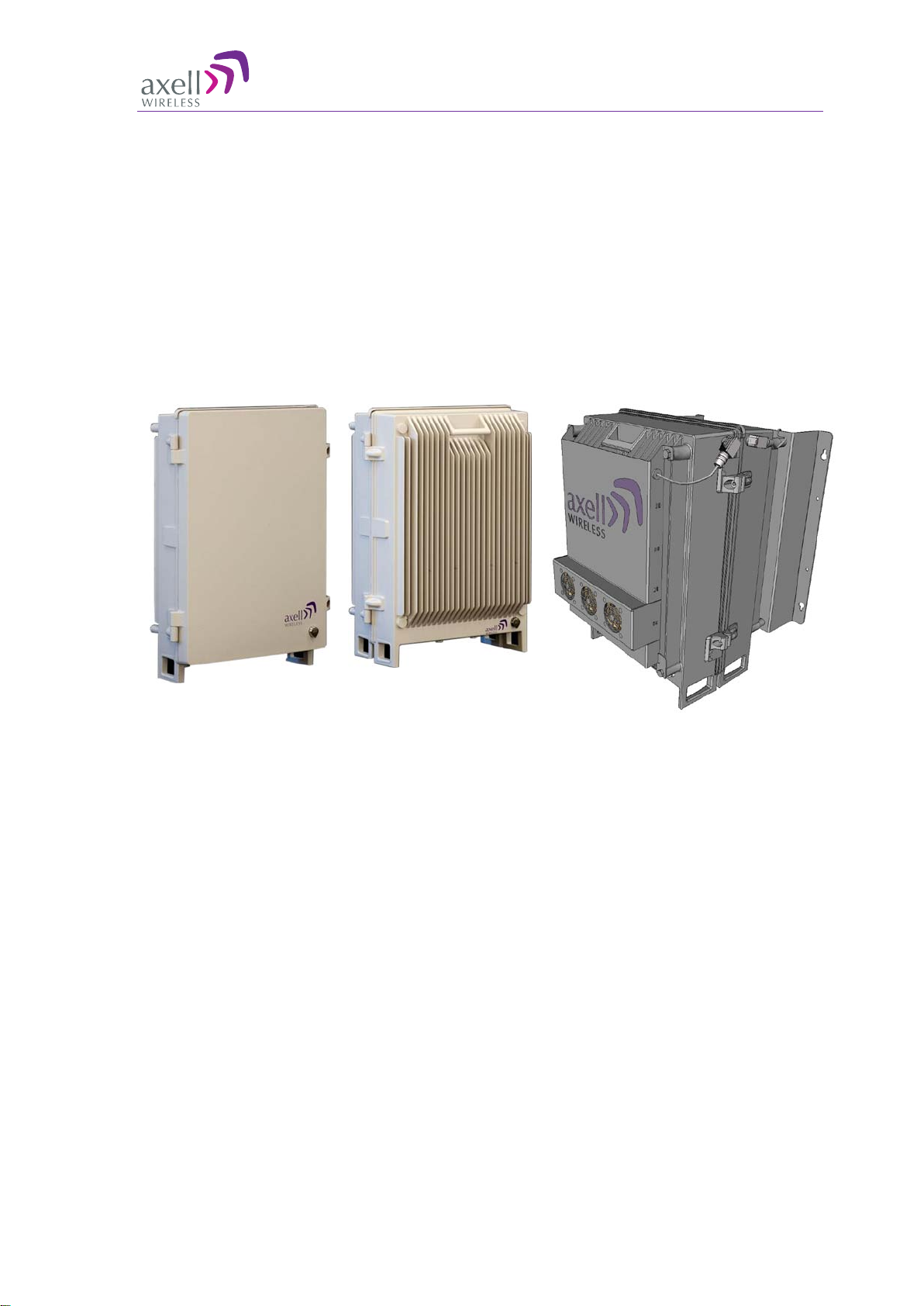
AXELL MBF -40 AMERICAS REPEATERS
PRODUCT DESCRIPTION AND USER’S MANUAL
X Doc. No. 00071UM Rev. 3.2 © Axell Wireless Ltd
3.5 Grounding....................................................................................................................................... 35
3.6 Ensure Good EMV Protection....................................................................................................36
3.7 Fiber Optic Connection ...............................................................................................................38
3.8 External Alarm and Relay Connections.................................................................................. 41
3.8.1 External Alarm................................................................................................................... 41
3.8.2 Relay................................................................................................................................... 41
3.9 Power and Backup Battery.........................................................................................................42
3.9.1 Dual Power Supply Models ............................................................................................. 42
3.9.2 Circuit Breaker................................................................................................................... 42
3.9.3 Connecting the Power Source ........................................................................................43
3.9.4 115 VAC Power Source................................................................................................... 43
3.9.5 -48V Power Source Connection...................................................................................... 44
3.9.6 Backup Battery.................................................................................................................. 45
3.10Power ON........................................................................................................................................46
3.10.1 Switching Power ON.........................................................................................................46
3.10.2 Verifying LEDs................................................................................................................... 46
3.11Closing and Securing the Repeater......................................................................................... 46
4Opening a Session and Navigating GUI ...........................................................................47
4.1 Opening a Direct Web Session..................................................................................................47
4.1.1 Connecting Locally............................................................................................................ 47
4.1.2 Remote Connection and Login ....................................................................................... 48
4.2 Open a Session to the MBF-40 via the OMU II.......................................................................49
4.3 Navigating the Web Interface.....................................................................................................50
4.3.1 Management Options Buttons......................................................................................... 51
4.3.2 Home Screen Overview................................................................................................... 52
4.3.3 Configuration Screen Overview...................................................................................... 53
4.3.4 Five Service System GUI................................................................................................. 54
5MBF-40 Commissioning........................................................................................................56
5.1 MBF-40 Optical Loss Adjustment (OLA).................................................................................56
5.2 RF Balancing.................................................................................................................................. 58
5.2.1 Manual RF Balancing....................................................................................................... 58
5.2.2 Automatic MBF-40 RF Balancing ................................................................................... 60
5.3 Integration into the AEM .............................................................................................................61
5.4 What Next? .....................................................................................................................................61
6MBF-40 Full GUI Description ...............................................................................................62
6.1 Configuring General Parameters..............................................................................................62
6.1.1 Site Information – MBF-40 Identification ....................................................................... 62
6.1.2 Date & Time....................................................................................................................... 63
6.1.3 Configure External Alarms............................................................................................... 63
6.1.4 IP Address..........................................................................................................................64
6.2 Remote Communication Setup .................................................................................................65
6.2.1 TCP/IP and Ethernet ........................................................................................................ 65
6.3 SNMP Support ...............................................................................................................................66
6.4 User Accounts...............................................................................................................................67
6.4.1 Default User Accounts......................................................................................................67
6.4.2 User Access Levels.......................................................................................................... 67
6.4.3 Change Password............................................................................................................. 68
6.5 Reboot .............................................................................................................................................68
6.6 Axell Shell (Command Line Interface).....................................................................................69
6.7 Attribute Reference ......................................................................................................................70