Axiall Accu-Tab 2000 P Series User manual

Accu-Tab®Systems
2000 P Series by
Axiall Corporation
Installation and Operating Instructions
Models 2075 P
2150 P
For NSF/ANSI-Standard 61
NSF®applications use NSF/ANSI
Standard 60 listed Axiall Accu-Tab®
STANDARD 61 SI Tablets and limit to no more
than 15 mg/l of tablet addition
(or 10 mg/l chlorine) to the treated
drinking water.
Rev 02-10-21
DANGER:
DO NOT MIX CHEMICALS!
The Accu-Tab® chlorinator is designed for use with
Axiall approved tablets only. Do not use Cal-Hypo
tablets with stabilized chlorine or bromine products,
or other sanitizing chemicals.
Fire or explosion could result.

2
SystemDescription
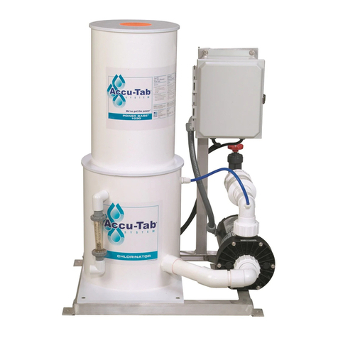
The Accu-Tab®tablet chlorinator system incorporates a patented Axiall chlorinator, which is designed to utilize
Axiall’s Accu-Tab®SI calcium hypochlorite tablets. The chlorinator is mounted on an aluminum frame.
Included in the system is an integrated, level controlled solution tank and discharge pump. Using a manually
adjusted valve and flow meter the amount of water through the chlorinator is controlled. This results in a
constant and predictable rate of chlorine delivery. The feeder is designed for use ONLY with Axiall AccuTab
®SI tablets to utilize the Axiall erosion feeder technology that erodes only the bottom layer of tablets on the
sieve plate, while keeping tablets above the sieve plate dry and ready for use. Tablets other than Axiall
AccuTab® SI tablets will have different delivery rates, resulting in improper chlorine delivery.
Optional Weight Scale
The weight scale incorporates 3 weigh cells integrated into the base of the chlorinator (upper section). The weigh
cells rest on the solution tank lid. Drip pipes extend from the chlorinator bottom through the solution tank lid to
prevent water or chlorine solution from directly contacting the weigh cells. It is important to keep the air gap
between the chlorinator and solution tank clean and dry. The weight scale instructions are included as a separate
manual.
How to calculate chlorine delivery needed
Information required:
System flow rate in USgpm (gpm)
Chlorine demand of water to be treated (Demand ppm)
Chlorine residual desired (Residual ppm)
Formula is: gpm x (Demand ppm + Residual ppm) x 0.0005 = lbs. Cl2/hr From
charts on page 5, determine initial flow setting for chlorinator.
Take chlorine residual readings and adjust flow to chlorinator until desired residual is reached.

3
Installation and Start-Up Instructions
A. Uncrate, remove from pallet, and check for damage that may have occurred during shipping. If
damage occurred during shipment, file a claim with the shipping company.
B. If the Weight Scale option was purchased, remove the blocking under the scale that was used
for protection during shipment. NOTE that there is a separate manual for the weight scale.
C. Place the chlorination system in a location near the place of application.
D. Level the system with the supplied leveling bolts. This is important for proper chlorine delivery.
E. Install a pressure regulator on the inlet supply line IF inlet line pressure is greater than 50 psi.
Tank flooding will result if pressure exceeds 50 psi.
F. Float valve is rated to 50 psi. If supply exceeds 50 psi when water system is shut down, a
solenoid valve is required to be installed on the inlet line to prevent chlorination system
flooding. The solenoid valve must be interlocked with your water system pump. Solenoid valve
is not supplied with the P system.
G. Connect Power and Run signal wires (either 110v or dry contact) to the electrical box.
Schematics are shown on pages 6 & 7. A solenoid valve is recommended for municipal water
applications.
H. Connect the inlet flow meter assembly to the solution tank (the parts were shipped loose to
prevent breakage in shipping).
I. Connect the inlet water supply with 1-1/2” PVC pipe or hose. Include an isolation valve at the
main header line. If source water contains debris, include a filter in the line.
J. Connect the chlorine control and check valve assembly to the pump discharge. Close the
chlorine control valve completely. (The parts were shipped loose to prevent breakage in
shipment.)
K. Connect the discharge piping from the chlorine control valve to the chlorine application point
with 1-1/2” PVC pipe or hose. Include an isolation valve at the main header line.
L. Once the water input and output connections are in place, open isolation valves and check for
leaks. Water will begin to flow into the chlorinator and fill the solution tank.
M. Wait until water stops flowing into the solution tank. Open the chlorine control valve about 2-3
full turns, and break loose the upstream union on the flap check valve to prime the pump.
When water flows out, pump should be primed. Tighten union and start the discharge pump.
There is a delay timer for the pump. This is to prevent chattering under low level situations.

4
N. Slowly, and in small, ¼ turn increments, continue to open the chlorine control valve to maintain
the desired inlet flow.
O. The chlorine delivery is determined by the flow rate through the chlorinator (see graphs).
NOTE: After adjusting the chlorine control valve, the flow meter will take a few moments to
stabilize.
P. Turn the main water system OFF and ON several times, allowing it to operate for several
minutes each time. Check all connections for leaks.
Q. To begin chlorinating, remove the chlorinator lid and fill the Chlorinator with Axiall Accu-Tab®SI
tablets.
R. NOTE: Add only the amount of tablets that will be consumed in 5-7 days. Tablets in the
chlorinator longer than 5-7 days will pick up moisture and bridging may occur.
Installation –Typical

5
Models 2075 P and 2150 P Schematic
Model 2075 P shown
0
0.5
1
1.5
2
2.5
3
0
2
4
6
8
10
12
14
16
18
20
Flow Rate, GPM
Model 2075
Using Accu®
-
Tab SI Tablets
For Industrial use only

6
0
5
10
15
0
10
20
30
40
50
60
Flow Rate, GPM
Model 2150
Using Accu®
-
Tab SI Tablets
For Industrial use only

7

8

9
Operating and Maintenance Instructions
A. Clean the Check Valve at least every 4-6 months, to remove debris or scale.
B. Disassemble Float Valve and clean every 6 months
C. Cleaning the chlorination system
Over time, and depending on the water chemical characteristics, some calcium scale may
build up in the system. Following procedure to clean:
1. Prepare 2 gallons of weak acid (~5%) solution.
2. Open doors and windows for ventilation.
3. Reduce the tablet volume in the chlorinator by operating the system to deplete the
tablets.
4. Physically remove any remaining tablets or pieces of tablets. Store in a safe manner
(empty, clean Accu-Tab®SI tablet pail).
5. Operate the system for 30 minutes to flush out all remaining chlorine solution, and hose
down inside of chlorinator walls.
6. Shut down the system, and close isolation valve on line feeding the system
7. Drain tank level down to about ¾ tank if necessary to prevent system from overflowing
while adding cleaning acid
8. Close the discharge isolation valve.
9. Very slowly and carefully pour the weak acid solution into chlorinator.
CAUTION: AS ACID DISSOLVES SCALE, CARBON DIOXIDE WILL BE RELEASED,
AND FOAMING WILL OCCUR. IF ANY CHLORINE WAS LEFT IN THE TANK OR
CHLORINATOR, CHLORINE GAS MAY ALSO BE RELEASED.
10.Allow to stand for 10-15 minutes.
11.Open isolation valves on the inlet and discharge to the system.
12.Be prepared to handle some acid being discharged to your water system.
13.Operate the chlorination system for 30 minutes to flush acid, and thoroughly wash out
chlorinator with a hose.
14.Shut system down.
15.Inspect for any debris in the chlorinator or tank, and remove if found.
16.Add tablets and restart system to resume chlorination.

10
Operating Troubleshooting Guide
A. Solution Tank level runs low
This can lead to inconsistent chlorine residuals. And can allow air to be pulled into the
discharge pump, causing pump to lose prime. Follow the procedure to adjust:
1. Make sure pump is primed.
2. Start pump.
3. Slowly, and using small increments, close the chlorine control valve until the
solution tank level is stabilized, and no air is being drawn into the pump.
B. Solution Tank overflows
1. Check valve has debris in it and is allowing water to back flow.
2. Float valve is not shutting off flow to the system.
3. Float valve has failed.
4. Inlet pressure is greater than 50 psi. Add pressure regulator and/or solenoid valve on inlet
line.
C. Pump will not run.
1. Check voltage at Disconnect switch.
2. Check circuit breakers.
3. Check voltage at pump contactor.
4. If H/O/A switch in AUTO, check run signal.
5. If H/O/A switch in HAND, check for voltage across Terminals A1 & A2 on pump contactor. If
110v across A1 & A2, manually push in contactor.
If pump runs, contactor bad.
If contactor pulled in, and voltage on output side of contactor, pump motor bad.
6. Check for low level in solution tank.
D. Contact Axiall Technical Service (855-934-3570) for assistance.
E. Float Valve was installed in a lower flow position. Float valve may be adjusted for higher flow.
Call Axiall for instructions.
Chlorinator Top Orientation
Align the chlorinator top portion so that the pointer on the separation plate is directly over the inlet.
See photo below. This will prevent chlorine solution from draining directly onto the float valve assembly.
Pointer
Inlet (where flow
meter is attached)

11
CAL-HYPO SYSTEM
LIMITED WARRANTY
Axiall, a Westlake Company ("Axiall") warrants (subject to the below conditions) only its title to this water treatment system
equipment (the "System") and that the System will be free of defects in materials and workmanship for a period of eighteen (18)
months from its original shipment date.
THIS IS THE ONLY REPRESENTATION OR EXPRESS WARRANTY THAT AXIALL MAKES AND ALL OTHER EXPRESS
WARRANTIES UNDER STATUTE OR ARISING OTHERWISE IN LAW FROM A COURSE OF DEALING OR USAGE OF TRADE
WITH RESPECT TO THE SYSTEM ARE DISCLAIMED. ANY IMPLIED WARRANTIES EXISTING AS A MATTER OF LAW
SHALL NOT EXCEED THE DURATION OF THIS LIMITED WARRANTY. IN THE EVENT THE SYSTEM FAILS TO CONFORM
TO THIS WARRANTY, AXIALL'S EXCLUSIVE OBLIGATION AND YOUR EXCLUSIVE REMEDY SHALL BE LIMITED TO, AT
AXIALL'S OPTION, THE FURNISHING OF NEEDED REPLACEMENT PARTS OR THE FURNISHING OF A NEW SYSTEM
(BUT THIS DOES NOT INCLUDE INSTALLATION OR THE COSTS FOR INSTALLATION). EXCEPT AS PROVIDED IN THE
IMMEDIATELY PRECEDING SENTENCE, IN NO EVENT WILL AXIALL BE LIABLE UNDER ANY THEORY OF RECOVERY
(WHETHER BASED ON NEGLIGENCE OF ANY KIND, STRICT LIABILITY OR TORT) FOR ANY DIRECT, INDIRECT, SPECIAL,
INCIDENTAL, PUNITIVE, OR CONSEQUENTIAL DAMAGES IN ANY WAY RELATED TO ANY USE MADE OF THE SYSTEM.
Warranty Conditions. This Limited Warranty shall apply and be effective only if: (i) the System is installed and operated and
maintained in accordance with this manual and the instructions accompanying the System; (ii) you, at your cost, promptly return
the System or defective part to such location as may be specified by Axiall; and, (iii) only Axiall’s Accu-Tab® SI calcium
hypochlorite tablets are used in the System. If any of these conditions are not met, this Limited Warranty will not apply and you
acknowledge and agree that your purchase of the System will be on an "AS-IS" basis without any warranty of any kind whatsoever
having been provided by Axiall.
You assume all responsibility and risk and liability arising from: (i) the unloading, installation, storage, handling and use of the
System, including use thereof alone or in combination with other materials; (ii) the improper functioning or failure of unloading,
installation, transportation or storage equipment you use, whether furnished or recommended by Axiall or not; and, (iii) the failure
to comply with laws, rules and regulations governing storage, unloading, installation, handling, and use of the System. You will
indemnify, hold harmless, and defend Axiall from and against any claim, suit, damage, cost, expense, fine, liability, or cause of
action whatsoever, including reasonable attorney fees, on account of relating to, or arising out of the use, possession, installation
or resale of the System.
This Limited Warranty gives you specific rights, and you also may have other rights, which vary from jurisdiction to jurisdiction.
Some jurisdictions do not allow the exclusion or limitation of incidental or consequential damages, so the above limitations or
exclusions may not apply to you. Some jurisdictions do not allow limitations on how long an implied warranty lasts, so the above
limitation may not apply to you.
This manual suits for next models
2
Other Axiall Swimming Pool Filter manuals
Popular Swimming Pool Filter manuals by other brands

Bestway
Bestway Hmax 58498E owner's manual

LASWIM
LASWIM EC Series Installation and user manual

Jandy
Jandy CS100 Installation and operation manual

Regal
Regal SMARTVALVES Instruction bulletin

XtremepowerUS
XtremepowerUS 90151 Owner's manual and safety instructions

Hayward
Hayward SandMaster SM1700T Series owner's manual