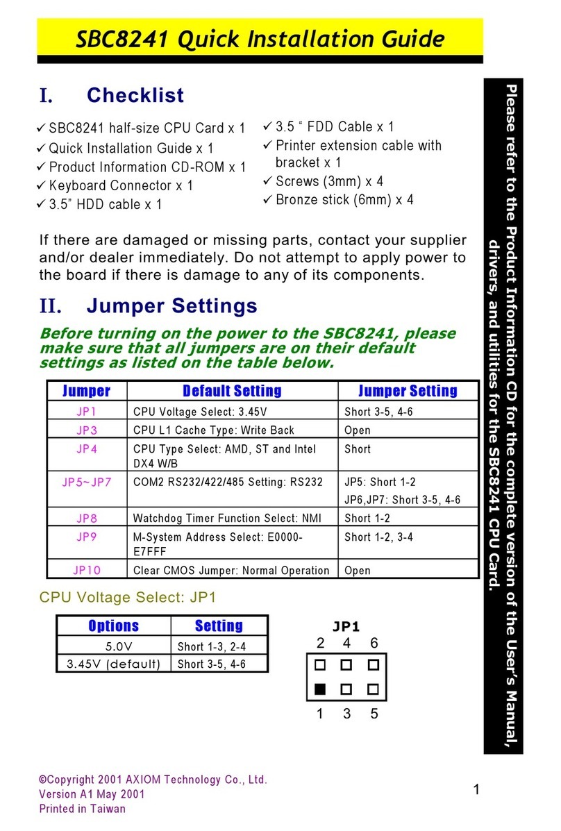
Axiom SBC8163 User manual


!
" !
#
!! !
!
"#$#

AXIOM is a trademark of AXIOM Technology Co., Ltd.
IBM is a registered trademark of International Business
Machines Corporation.
MS-DOS, and Windows 95/98/NT/2000 are trademarks of
Microsoft Corporation.
Award is a trademark of Award Software, Inc.
IBM, PC/AT, PS/2, VGA are trademarks of International
Business Machines Corporation.
Intel and Celeron, Pentium III are trademarks of Intel
Corporation.
ATI is a trademark of ATI Technologies Inc.
Other brand names and trademarks are the properties and
registered brands of their respective owners.


Table of Contents
Chapter 1
Chapter 1Chapter 1
Chapter 1 Introduction
IntroductionIntroduction
Introduction
1.1 General Description .................................. 1
1.2 Specifications ............................................ 2
1.3 Utilities Supported.................................... 3
1.4 Board Dimensions ....................................... 4
Chapter 2
Chapter 2Chapter 2
Chapter 2 Jumpers and Connectors
Jumpers and ConnectorsJumpers and Connectors
Jumpers and Connectors
2.1 Board Layout .............................................. 5
2.2 Jumper Settings ......................................... 6
2.2.1 Internal Keyboard Connector Power Selection: JP16 ...... 6
2.2.2 VGA Controller Interrupt Control: JP4 ............................. 7
2.2.3 Power Supply Type Selection: JP11 ................................ 7
2.2.4 Watchdog Trigger Mode Setting: JP14 ........................... 7
2.2.5 DiskOnChip Memory Segment: JP12 .............................. 7
2.2.6 SCSI Function Interrupt Control: JP7 ............................... 7
2.2.7 COM2 RS232/422/485 Settings: JP1,JP2,JP3.................... 8
2.3 Connectors ................................................ 9
Chapter 3
Chapter 3Chapter 3
Chapter 3 Installation
InstallationInstallation
Installation
3.1 System Memory ......................................... 11
3.2 CPU Installation...................................... 11
3.3 Completing Installation .......................... 12
Chapter 4
Chapter 4Chapter 4
Chapter 4 Hardware Description
Hardware DescriptionHardware Description
Hardware Description
4.1 Microprocessors ...................................... 13
4.2 BIOS ......................................................... 13
4.3 I/O Port Address Map................................ 14
4.4 Interrupt Controller.............................. 15
4.5 General Output Connector ...................... 16
4.6 Enhanced IDE Interface Connector.......... 17
4.7 VGA Interface .......................................... 18
4.7.1 CRT Interface Controller...............................................18
4.7.2 Features......................................................................18
4.7.3 VGA Connector: CN18 .................................................18
4.8 Ethernet Connector ................................ 19
4.9 SCSI Connector ........................................ 19
4.10 Floppy Disk Controller ........................... 19
4.11 Parallel Port Interface.......................... 20
4.12 Serial Port Interface .............................. 20
4.12.1 Serial Ports IRQ Selection .............................................20

Table of Contents
4.13 Keyboard and PS/2 Mouse Connectors ...... 21
4.14 USB Connector......................................... 21
4.15 IrDA Connector ........................................ 22
4.16 ACPI Connector ........................................ 22
Chapter 5
Chapter 5Chapter 5
Chapter 5 Display Drivers
Display DriversDisplay Drivers
Display Drivers
5.1 Introduction ............................................ 23
5.2 Features .................................................. 23
5.3 Drivers Supported ................................... 24
Chapter 6
Chapter 6Chapter 6
Chapter 6 Ethernet
EthernetEthernet
Ethernet
6.1 Introduction ............................................ 25
6.2 Features .................................................. 25
6.3 Drivers Supported ................................... 25
Chapter 7
Chapter 7Chapter 7
Chapter 7 SCSI Controller
SCSI ControllerSCSI Controller
SCSI Controller
7.1 Introduction ............................................ 27
7.2 Features .................................................. 27
7.3 Driver Support......................................... 28
Chapter 8
Chapter 8Chapter 8
Chapter 8 Award BIOS Utility
Award BIOS UtilityAward BIOS Utility
Award BIOS Utility
8.1 BIOS Introduction .................................... 29
8.2 BIOS Setup ............................................... 29
8.3 Standard CMOS Setup............................... 31
8.4 BIOS Features Setup ................................ 34
8.5 Chipset Features Setup ........................... 38
8.6 Power Management Setup......................... 41
8.6.1 PM Timers ....................................................................43
8.6.2 PM Events....................................................................43
8.6.3 Reload Global Timer Events..........................................45
8.7 PNP/PCI Configuration ............................. 45
8.8 Load BIOS Defaults .................................. 47
8.9 Load Setup Defaults ................................ 48
8.10 Integrated Peripherals ........................... 49
8.11 Supervisor / User Password..................... 52
8.12 IDE HDD Auto Detection ........................... 53
8.13 Save & Exit Setup ..................................... 54
8.14 Exit Without Saving.................................. 55
Appendix A
Appendix AAppendix A
Appendix A Watchdog Timer
Watchdog TimerWatchdog Timer
Watchdog Timer
Using the Watchdog Function........................... 57

Table of Contents
Appendix B
Appendix BAppendix B
Appendix B Connector Pin
Connector PinConnector Pin
Connector Pin
Assignments
AssignmentsAssignments
Assignments
40-pin IDE Interface Connector: CN6 ...............................................59
Floppy Disk Connector: CN2............................................................59
Parallel Port Connector: CN3...........................................................60
Serial Ports Pin Assignment ............................................................60
USB Connector: CN10 .....................................................................61
Case Fan Connector: CN23 .............................................................61
CPU Fan Connector: CN24 ..............................................................61
WAKE ON LAN Connector: CN4.......................................................61


SBC8163 Socket370 All-in-One CPU Card Series User’s Manual
Introduction !
!"
"#$"#$
%%&'()#(
*'+()#,'-)(
#".
#"+
/01&"#$

SBC8163 Socket370 All-in-One CPU Card Series User’s Manual
Introduction
,
# "$
zChipset: Intel 440BX AGPset
zCPU Socket: Socket370
zBus Clock: 66/100 MHz
zCPU: Intel Socket370 Celeron/Pentium III up to 800MHz
zL2 Cache: Integrated in CPU
zBIOS: Award 2MB PnP Flash BIOS
zSystem Memory:
3 x 168-pin DIMM sockets
Maximum buffered SDRAM 256MB or unbuffered SDRAM 128MB,
up to 768MB SDRAM
ECC/parity checking
zIDE Interface: 2 bus mastering EIDE up to four
devices, Ultra DMA/33 supported
zFDD Interface: Supports up to 2 drives
zSerial Ports: Two 16550 UARTs ports with 16 byte as
one RS-232 and one RS-232/422/485
zParallel Ports: One parallel port with ECP/EPP/SPP
supported
zVGA Controller:
AGP interface controller with onboard 8MB SDRAM
VGA chipset ATI Rage XL AGP 2X supporting CRT displays
Supports up to 1600x1200 16 bit-color resolution on non-
interlaced CRT monitors
zEthernet:
Intel 82559 PCI Bus 10/100M Base-T
Onboard Wake On LAN (via ATX power supply)
Onboard RJ-45 connector

SBC8163 Socket370 All-in-One CPU Card Series User’s Manual
Introduction 0
zUltra3 Wide SCSI:
LSI Symbios SYM53C1010 PCI Bus Ultra3 Wide SCSI interface
Two 68-pin 16-bit differential Ultra3 Wide SCSI ports and one 50-
pin 8-bit Ultra SCSI port
Connects up to 30 SCSI peripherals whit Ultra3 Wide SCSI feature
Provide data transfer rates up to 160MB/sec whit Ultra3 Wide
SCSI, 80MB/sec whit Ultra2 Wide SCSI, 40MB/sec whit Ultra Wide
SCSI, and 20MB/sec with Ultra SCSI interface
zUSB Interface: 2 USB ports; USB Spec. Rev. 1.1
compliant
zIrDA: 1 IrDA pin-header for wireless communication
zHardware Monitoring: Winbond W83781D controller,
monitoring for CPU/System
temperature, system voltage,
and fan speed
zWatchdog Timer:
Generates a system reset
Software programmable time interval and jumper selectable
64 levels, 0.5~8/5~80/50~800/100~1600 seconds
zSSD: Supports M-Systems DiskOnChip 2000 serials
zDimensions: 122(W) x 335(L) mm
NOTE: Specifications are subject to change without notice.
""
zSCSI Utility and Drivers (SCSI functions only)
zEthernet Utility and Drivers
zCRT Drivers
zSystem Doctor

SBC8163 Socket370 All-in-One CPU Card Series User’s Manual
Introduction
%
% &

SBC8163 Socket370 All-in-One CPU Card Series User’s Manual
Jumpers and Connectors 2
# &'(

SBC8163 Socket370 All-in-One CPU Card Series User’s Manual
Jumpers and Connectors
.
# # )"*
34
4
5
Jumper Default Setting Jumper
Setting
JP1 COM2 Mode Setting: RS232 Short 3-5, 4-6
JP2 COM2 Mode Setting: RS232 Short 1-2, 7-8
JP3 COM2 Mode Setting: RS232 Short 3-5, 4-6
JP4 VGA Interrupt require: Use Interrupt Open
JP5 Reserved Open
JP6 Reserved Open
JP7 SCSI Function: Use Dual Interrupt Open
JP8 ----- -----
JP9 Reserved Open
JP10 Reserved Short 1-2
JP11 Power Supply Type: AT Power Supply Short 1-2, 4-5, 7-
8, 10-11
JP12 DiskOnChip Memory Segment DC000-DFFFF Short 7-8
JP13 Reserved Open
JP14 Watchdog Trigger Mode: Disabled Open
JP15 ----- -----
JP16 Int. Keyboard Power Select: System Power Short 1-2
Power Source Settings
System Power Short 1-2 (default)
Suspend Power Short 2-3
JP16

SBC8163 Socket370 All-in-One CPU Card Series User’s Manual
Jumpers and Connectors 1
Options Settings
Use Interrupt Open (default)
Non-Interrupt Short
!
Options Settings
AT P/S (default) Short 1-2, 4-5, 7-8, 10-11
ATX P/S Short 2-3, 5-6, 8-9, 11-12
"#$!$$%$
"#$
63"#$
Options Setting
NMI Short 1-2
RESET Short 2-3
Disabled Open (default)
& '()*#%+$+
Options Settings
D0000 D3FFF Short 1-2
D4000 D7FFF Short 3-4
D8000 DBFFF Short 5-6
DC000 DFFFF Short 7-8 (default)
,-
Options Settings
Use Dual Interrupt Open (default)
Use One Interrupt Short

SBC8163 Socket370 All-in-One CPU Card Series User’s Manual
Jumpers and Connectors
7
- *%. //0&$(11
COM2 JP1 JP2 JP3
RS-232 (default) Short 3-5, 4-6 Short 1-2, 7-8 Short 3-5, 4-6
RS-422 Short 1-3, 2-4 Short 3-4 Short 1-3, 2-4
RS-485 Short 1-3, 2-4 Short 5-6, 7-8 Short 1-3, 2-4

SBC8163 Socket370 All-in-One CPU Card Series User’s Manual
Jumpers and Connectors 8
#
"#$
/
9
"%(:
Connectors Label Connectors Label
Primary IDE Connector
Primary IDE ConnectorPrimary IDE Connector
Primary IDE Connector CN1 ACPI Connector
ACPI ConnectorACPI Connector
ACPI Connector CN17
FDD Connector
FDD ConnectorFDD Connector
FDD Connector CN2 VGA Connector
VGA ConnectorVGA Connector
VGA Connector CN18
Printer Port Connector
Printer Port ConnectorPrinter Port Connector
Printer Port Connector CN3 Extrnal Battery Connector
Extrnal Battery ConnectorExtrnal Battery Connector
Extrnal Battery Connector CN20
COM1 (SBC8163VES And
COM1 (SBC8163VES AndCOM1 (SBC8163VES And
COM1 (SBC8163VES And
SBC8163VE Only)
SBC8163VE Only)SBC8163VE Only)
SBC8163VE Only) CN4 Reserved
ReservedReserved
Reserved CN21
Secondary IDE Connector
Secondary IDE ConnectorSecondary IDE Connector
Secondary IDE Connector CN5 USB Connector
USB ConnectorUSB Connector
USB Connector CN22
50-pin Narrow SCSI
50-pin Narrow SCSI50-pin Narrow SCSI
50-pin Narrow SCSI
Connector
ConnectorConnector
Connector CN6 PS/2 Keyboard Connector
PS/2 Keyboard ConnectorPS/2 Keyboard Connector
PS/2 Keyboard Connector CN23
COM2
COM2COM2
COM2 CN7 PS/2 Mouse Connector
PS/2 Mouse ConnectorPS/2 Mouse Connector
PS/2 Mouse Connector CN24
-----
----------
----- CN8 Keyboard/Mouse
Keyboard/MouseKeyboard/Mouse
Keyboard/Mouse
Connector
ConnectorConnector
Connector CN25
68-pin Ultra3(2) Wide SCSI
68-pin Ultra3(2) Wide SCSI68-pin Ultra3(2) Wide SCSI
68-pin Ultra3(2) Wide SCSI
Connector With Channel 1
Connector With Channel 1Connector With Channel 1
Connector With Channel 1 CN9 Fan Power Connector 2
Fan Power Connector 2Fan Power Connector 2
Fan Power Connector 2 CN26
68-pin Ultra3(2) Wide SCSI
68-pin Ultra3(2) Wide SCSI68-pin Ultra3(2) Wide SCSI
68-pin Ultra3(2) Wide SCSI
Connector With Channel 2
Connector With Channel 2Connector With Channel 2
Connector With Channel 2 CN10 SCSI Channel 1 LVD Mode
SCSI Channel 1 LVD ModeSCSI Channel 1 LVD Mode
SCSI Channel 1 LVD Mode
directives
directivesdirectives
directives LED Connector
LED ConnectorLED Connector
LED Connector D2
General Output Connector
General Output ConnectorGeneral Output Connector
General Output Connector CN11 SCSI Channel 2 LVD Mode
SCSI Channel 2 LVD ModeSCSI Channel 2 LVD Mode
SCSI Channel 2 LVD Mode
directives
directivesdirectives
directives LED Connector
LED ConnectorLED Connector
LED Connector D4
Reserved
ReservedReserved
Reserved CN12 Watch-Dog Activity LED
Watch-Dog Activity LEDWatch-Dog Activity LED
Watch-Dog Activity LED
Connector
ConnectorConnector
Connector D6
Fan Power Connector 1
Fan Power Connector 1Fan Power Connector 1
Fan Power Connector 1 CN13 SCSI Channel 2 Activity
SCSI Channel 2 ActivitySCSI Channel 2 Activity
SCSI Channel 2 Activity
LED Connector
LED ConnectorLED Connector
LED Connector D7
IrDA Connector
IrDA ConnectorIrDA Connector
IrDA Connector CN14 SCSI Channel 1 Activity
SCSI Channel 1 ActivitySCSI Channel 1 Activity
SCSI Channel 1 Activity
LED Connector
LED ConnectorLED Connector
LED Connector D9
Ethernet Connector
Ethernet ConnectorEthernet Connector
Ethernet Connector
(SBC8163VES & VE Only)
(SBC8163VES & VE Only)(SBC8163VES & VE Only)
(SBC8163VES & VE Only) CN15 Ethernet Boot ROM Socket
Ethernet Boot ROM SocketEthernet Boot ROM Socket
Ethernet Boot ROM Socket U16
COM1 (SBC8163V Only)
COM1 (SBC8163V Only)COM1 (SBC8163V Only)
COM1 (SBC8163V Only) CN16 DiskOnChip
DiskOnChipDiskOnChip
DiskOnChip
Socket
SocketSocket
Socket U22
External LAN Card Wake On
External LAN Card Wake OnExternal LAN Card Wake On
External LAN Card Wake On
LAN Connector
LAN ConnectorLAN Connector
LAN Connector CN19

SBC8163 Socket370 All-in-One CPU Card Series User’s Manual
!&

SBC8163 Socket370 All-in-One CPU Card Series User’s Manual
Installation !!
/01&"#$
;
Power supply and passive backplane (optional)
IBMPC/AT keyboard
Display monitor
Floppy or hard disk with MS-DOS or Flash Disk emulator
((
"#$!.733
<33=:
!,73/*(3,2.3/*(3
>!.30,3.%3
!,73,2.3<=/*(3
NOTE: Use SDRAM modules with PC100 or PC133 specification
when running 100MHz CPU bus speed. With 66MHz CPU
bus speed, SDRAM modules with PC66, PC100 or PC133
specification can be used. You have to install the Intel
Celeron or Pentium III processor before installing the
memory modules.
# +
1. Align pin one (e.g., white dot) of the CPU with pin one of the
socket. Pin one of the CPU socket may either be marked on
the board or indicated by an arrow head symbol on one
corner of the socket. Normally, its diagonal corner
distinguishes pin one on the socket.
2. To complete the CPU installation, gently press the CPU into
place.
3. Double-check the insertion and orientation of the CPU before
applying power. Improper installation will result in permanent
damage to the CPU.

SBC8163 Socket370 All-in-One CPU Card Series User’s Manual
Installation
!,
"*+
1. Make sure the power is OFF.
2. Set the configuration jumpers according to the jumper settings
on Chapter 2.
3. Install the SBC8163
SBC8163SBC8163
SBC8163 CPU card into one of the slots on the
passive backplane. You may allow the SBC8163
SBC8163SBC8163
SBC8163 to stand
alone as a single board computer.
4. Connect the I/O cables and peripherals, i.e. floppy disk, hard
disk, monitor, keyboard, power supply and etc. to the CPU
board.
NOTE: The color of pin one is usually red or blue,
while others are gray.
5. Turn ON the system power.
This manual suits for next models
1
Table of contents
Other Axiom Computer Hardware manuals
Popular Computer Hardware manuals by other brands

BE QUIET!
BE QUIET! Light Wings BL073 quick start guide

EK-Quantum
EK-Quantum Vector2 Strix RTX 3080 D-RGB user guide

Vantec
Vantec UGT-UC302CB user manual

Patton electronics
Patton electronics IM1RC/D user manual

Avaya
Avaya PARTNER ACS R7 Engineer’s Notes

Homeworks
Homeworks HQP7-RF-2 installation instructions