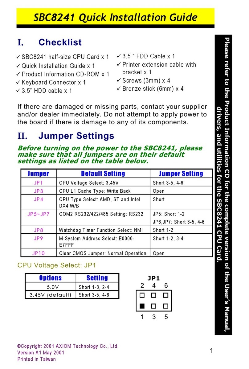
Axiom SBC8161 User manual


!
" !
#
!! !
!"
#$%$

!"
!"
!"
AXIOM is a trademark of AXIOM Technology Co., Ltd.
IBM is a registered trademark of International Business
Machines Corporation.
MS-DOS, and Windows 95/98/NT/2000 are trademarks of
Microsoft Corporation.
Award is a trademark of Award Software, Inc.
IBM, PC/AT, PS/2, VGA are trademarks of International
Business Machines Corporation.
Intel and Celeron, Pentium III are trademarks of Intel
Corporation.
C&T is a trademark of Chips and Technologies, Inc.
Realtek is a registered trademark of Realtek
Semiconductor Corporation.
Other brand names and trademarks are the properties and
registered brands of their respective owners.


Table of Contents
2.2.1Power Selection of Flat Panel Connector (VDDM
of CN2): JP5..............................................................7
2.2.2Power Supply Type Selection: JP7 ...........................7
2.2.3CMOS Clear Jumper: JP10.......................................7
2.2.4PS/2 Mouse Function Selection: JP11......................7
2.2.5Watchdog Trigger Mode Setting: JP12 ...................8
2.2.6DiskOnChipMemory Segment: JP14.....................8
2.2.7COM2 RS232/422/485 Settings: JP17, JP18, JP19 ....8
!"
#
!$%
#&' (%
!%
#
%)
%')$&#
%! *
)! +
,-%,%! "
*.&% "
4.7.1Flat Panel/CRT Interface Controller ......................19
4.7.2Features ..................................................................20
4.7.3VGA/Flat Panel Connector: CN17, CN2, CN1 ......20

Table of Contents
4.7.4Flat Panel Connector Pin Description...................22
+,-!
"!%!
/01!
$$%
$%
4.12.1Serial Ports IRQ Selection .......................................23
23$'#!
!
%&!
&!$%!
% *
0 *
( +
!
% "
0 "
( "
"#$%&
*%)%
*%)
*!#)
*!#)
*%)0
7.4.1Onboard VGA Functions........................................40
*!-0
* $4#
7.6.1PM Timers ................................................................45
7.6.2PM Events................................................................46
**$5$'$!%! *
*+%) "
*" /
*/%$-

Table of Contents
*('$4
*%,6&
*(7,8
*,89-(
'(')&*
'("+'& !
'(,-'./%


SBC8161 Socket 370 All-in-One CPU Card Series Users Manual
Introduction !
!"
"#$"#$
%&&#%'(")*+&,--
%'(")')&".".)*///
0%1&
#")
#"2
-
+3/"#$

SBC8161 Socket 370 All-in-One CPU Card Series Users Manual
Introduction
(
# "$
#"Chipset: VIA VT82C693A, VT82C686A with
integrated real-time clock
#"CPU Socket: Socket 370
#"Bus Clock: 66/100/133 MHz
#"CPU: Intel Socket 370 Celeron / Pentium III up to 1GHz
#"L2 Cache: Integrated in CPU
#"BIOS: Award 2MB PnP Flash BIOS
#"System Memory:
!"
3x168 pin DIMM sockets. Support up to 1.5GB SDRAM
#"IDE Interface: 2 bus mastering EIDE up to four devices,
Ultra DMA/66 supported
#"FDD Interface: Supports up to 2 drives
#"Serial Ports: Two 16550 UARTs ports with 16 byte as
one RS-232 and one RS-232/422/485
#"Parallel Ports: One parallel port with ECP/EPP/SPP
supported
#"VGA/Flat Panel Controller:
!"AGP interface controller with integrated 2MB SDRAM
!"VGA chipset C&T 69000 AGP 1x supporting CRT/LCD
displays
!"Supports up to 1280x1024 256-color resolution on non-
interlaced CRT monitors, and 1024x768 16 bit-color on
LCD panel monitors
#"Ethernet:
!"Realtek 8139 PCI Bus 10/100M Base-T
!"Onboard Wake On LAN (via ATX power supply)
!"Onboard RJ-45 connector

SBC8161 Socket 370 All-in-One CPU Card Series Users Manual
Introduction +
#"Ultra2 Wide SCSI:
!"Adaptec AIC-7890 PCI Bus Ultra2 Wide SCSI interface
and Adaptec AIC-3860 Ultra Wide/Narrow SCSI interface
!"One 68-pin 16-bit differential Ultra2 Wide SCSI port, one
68-pin 16-bit Ultra Wide SCSI port and one 50-pin 8-bit
Ultra SCSI port
!"Connects up to 15 SCSI peripherals whit Ultra2 Wide SCSI
feature
!"Provide data transfer rates up to 80 Mbytes/sec whit
Ultra2 Wide SCSI, 40 Mbytes/sec whit Ultra Wide SCSI
and 20 Mbytes/sec whit Ultra SCSI interface
#"USB Interface: two USB ports; USB Spec. Rev. 1.1
compliant
#"IrDA: 1 IrDA pin-header for wireless communication
#"Hardware Monitoring: Built-in VT86C686A, monitoring
for CPU/System temperature,
system voltage, and fan speed
#"Watchdog Timer:
!"
Generates a system reset
!"
Software programmable time interval and jumper
selectable
!"
64 levels, 0.5~8/5~80/50~800/100~1600 seconds
#"SSD: Supports M-Systems DiskOnChip2000 serials
#"Dimensions: 122(W) x 335(L) mm
NOTE:Specifications are subject to change without notice.
""
#"
VIA Chipset Drivers
#"
SCSI Utility and Drivers (SCSI functions only)
#"
Ethernet Utility and Drivers
#"
Flat panel/CRT Drivers
#"
System Doctor

SBC8161 Socket 370 All-in-One CPU Card Series Users Manual
Introduction
4
% &

SBC8161 Socket 370 All-in-One CPU Card Series Users Manual
Jumpers and Connectors 5
# &'(

SBC8161 Socket 370 All-in-One CPU Card Series Users Manual
Jumpers and Connectors
)
# # )"*
67
7
,
Jumper Default Function Setting Default Jumper Setting
JP1 ----- -----
JP2 ----- -----
JP3 ----- -----
JP4 ----- -----
JP5 Power Selection 3.3V of Flat Panel
Connector (VDDM of CN2) Short 2-3
JP6 ----- -----
JP7 Power Supply Type For AT Power Supply
Setting Short 1-3, 2-4
JP8 ----- -----
JP9 ----- -----
JP10 CMOS Clear Jumper For Normal Mode Short 1-2
JP11 PS/2 Mouse Function Enable Setting Short 1-2
JP12 Watchdog Disable Mode Setting Open
JP13 Reserved Open
JP14 DiskOnChip Memory Segment For DC000-
DFFFF Setting Short 7-8
JP15 ----- -----
JP16 Reserved Short
JP17 COM2 RS232 Settings Short 1-2, 7-8
JP18 COM2 RS232 Settings Short 3-5, 4-6
JP19 COM2 RS232 Settings Short 3-5, 4-6
JP20 ----- -----
JP21 ----- -----
JP22 ----- -----
JP23 ----- -----
Continued . . . . .

SBC8161 Socket 370 All-in-One CPU Card Series Users Manual
Jumpers and Connectors 3
Jumper Function Default
JP24 ----- -----
JP25 ----- -----
JP26 Reserved Open
VDDM Settings
5V Short 1-2
3.3V (default) Short 2-3
8++%85%
7
!
Options Settings
AT P/S (default) Short 1-3, 2-4
ATX P/S Short 3-5, 4-6
" #$%
Options Settings
Clear CMOS Short 2-3
Normal (default) Short 1-2
& '(
Options Settings
Enabled
(default) Short 1-2
Disabled Short 2-3

SBC8161 Socket 370 All-in-One CPU Card Series Users Manual
Jumpers and Connectors
'
)*+, ,,+,
"#$
96"#$
Options Setting
NMI (default) Short 1-2
RESET Short 2-3
Disabled Open
- (.#*
$,$&
Options Settings
D0000 D3FFF Short 1-2
D4000 D7FFF Short 3-4
D8000 DBFFF Short 5-6
DC000 DFFFF Short 7-8 (default)
! #/"'&'&0,(!101
2
COM2 JP19 JP18 JP17
RS-232 (default) Short 3-5, 4-6 Short 3-5, 4-6 Short 1-2
RS-422 Short 1-3, 2-4 Short 1-3, 2-4 Short 3-4
RS-485 Short 1-3, 2-4 Short 1-3, 2-4 Short 5-6, 7-8

SBC8161 Socket 370 All-in-One CPU Card Series Users Manual
Jumpers and Connectors *
#
"#$
-
:
"4
&;
Connectors And Socket Label
LCD-2 Connector CN1
LCD Connector CN2
General Output Connector CN3
External LAN Card Wake On LAN Connector CN4
Primary IDE Connector CN5
Secondary IDE Connector CN6
FDD Connector CN7
50-pin Narrow SCSI Connector
(Only by SBC8161VES) CN8
68-pin Ultra Wide SCSI Connector
(Only by SBC8161VES) CN9
68-pin Ultra2 Wide SCSI Connector
(Only by SBC8161VES) CN10
Printer Port Connector CN11
COM2 CN12
COM1 (Only by SBC8161VES and SBC8161VE) CN13
USB Connector CN14
Ethernet Connector
(Only by SBC8161VES and SBC8161VE) CN15
COM1 (Only by SBC8161V and SBC8161) CN16
VGA Connector CN17
Keyboard and Mouse Connector CN18
PS/2 Mouse Connector CN19
PS/2 Keyboard Connector CN20
Continued . . . . .

SBC8161 Socket 370 All-in-One CPU Card Series Users Manual
Jumpers and Connectors
!/
Connectors And Socket Label
IR Connector CN21
ACPI Connector CN22
Case Fan Connector CN23
CPU Fan Connector CN24
DiskOnChipSocket U15
Ethernet Boot ROM Socket U12

SBC8161 Socket 370 All-in-One CPU Card Series Users Manual
Installation !!
-+3/"#$
<
!"
Power supply and passive backplane (optional)
!"
IBMPC/AT keyboard
!"
Display monitor
!"
Floppy or hard disk with MS-DOS or Flash Disk emulator
((
"#$!)'
66=66>;
!51-?&6
@!)6+(6)46!('6(5)65!(6
-?&6
NOTE: Use SDRAM modules with PC100 or PC133
specification when running 100/133MHz CPU bus
speed. With 66MHz CPU bus speed, SDRAM modules
with PC66, PC100 or PC133 specification can be used.
You have to install the Intel Celeron or Pentium III
processor before installing the memory modules.
# +
1. Align pin one (e.g., white dot) of the CPU with pin one
of the socket. Pin one of the CPU socket may either be
marked on the board or indicated by an arrow head
symbol on one corner of the socket. Normally, its
diagonal corner distinguishes pin one on the socket.
2. To complete the CPU installation, gently press the CPU
into place.
3. Double-check the insertion and orientation of the CPU
before applying power. Improper installation will result

SBC8161 Socket 370 All-in-One CPU Card Series Users Manual
Installation
!(
in permanent damage to the CPU.
,--.+
$6&,))'/
=4/>
$6&,))
4$6&,))
#:"=>
-:"=>
'/
!"#
Table of contents
Other Axiom Computer Hardware manuals
Popular Computer Hardware manuals by other brands

JYTEK
JYTEK PCIe-68560 user manual

Fuji Electric
Fuji Electric OPC-G1-PG instruction manual

Freescale Semiconductor
Freescale Semiconductor TWR-S12GN32 quick start guide

Sony
Sony HFBK-HD1 Operation manual

Ctl
Ctl VoiceSupport Lx operating instructions

Acrosser Technology
Acrosser Technology AND-DNV3N3-R Series user manual