4
INTRODUCTION
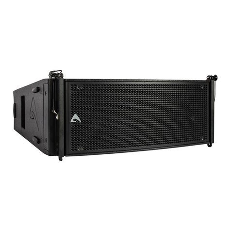
The AX2010P Vercal Line Array element is designed for a wide range of sound reinforcement applicaons where a exible and
easy to use vercal array systems is needed. The AX2010P has been designed both for rental live sound applicaons and for
xed installaons and has been engineered for the simplest use possible but without sacricing anything in sound quality and
performance.
The high frequency range is reproduced by two low-distoron compression drivers, equipped with very light-weight diaphragms.
Two transmission line waveforming waveguides have been used to load the HF drivers, in order to provide a detailed and natural
sound and to achieve a long-distance HF projecng capacity.
The two 10” woofers employed in the reproducon of the mid-bass range are equipped with very light-weight cones. The lightness
of the diaphragm is furthermore improved by the use of aluminium voice coil instead of convenonal copper. This ensure a fast
reproducon of the mid range and of mid-bass musical passages, improving also the thermal capacity of the voice coil and,
consequently, controlling the overall power compression. The two 10” woofers are back loaded by a short hybrid transmission
line that minimizes the eect of the box resonances and eliminates the “boxy” mid-bass sound commonly obtained from regular
bassreex enclosures.
The crossover lter approach is based on a “Constant Power” technique. Thanks to a parcular phase combinaon between the
two ways around the crossover frequency, this approach is able to provide a very stable horizontal coverage and a very stable o-
axys sound image, also minimizing unwanted eects around the crossover frequency. The further applicaon of phase linearizaon
techniques, combined to constant power crossover, yield a linear phase response and a coherent me response. This allows for a
natural percepon of acousc instruments and voices and for an improved depth of the sound image.
TECHNICAL SPECIFICATION
SYSTEM INPUT CONNECTION
System’s Acousc Principle
Line Array Element
Short Transmission Line LF Back Loading
Acousc Transmission Line HF Waveguide
Connector Type Neutrik® Speakon® NL4 x 2
Input Wiring Class D amplier with SMPS & PFC
POWER HANDLING
Frequency Response (±3dB) 75 Hz – 18 KHz (Processed) Continuous AES Pink Noise
Power 700W (LF) + 150W (HF)
Nominal Impedance 8ohm (LF) + 8ohm (HF)
Minimum Impedance 7.5ohm@300Hz (LF) 7ohm@2.5kHz (HF) Program Power 1400W (LF) + 300W (HF)
Sensivity (2.83V @ 1m, 2Pi) 99dBSPL (LF) 108dBSPL (HF)
LF Power Compression
@ -10 dB Power (70 W) = 0.5 dB
@ -3 dB Power (350 W) = 1.5 dB
@ 0 dB Power (700 W) = 3.2 dB
Horizontal Coverage Angle 110° (-6dB)
Vercal Coverage Angle 10° (-6dB)
Maximum Peak SPL @ 1m 138 dB ENCLOSURE & CONSTRUCTION
TRANSDUCERS Dimensions (W x H x D) 746 mm (29.37”) x 341 mm (13.42”) x
530 mm (20.86”)
LF
Two 10” (260 mm), 2.5” (64 mm)
aluminium voice coil, 16Ω each,
paralleled
Taper angle 5°
Construcon 15 mm, reinforced Phenolic Birch
HF
Two 1.4” drivers, 2.5” (64 mm)
edgewound voice coil, tanium
diaphragm, 16Ω each, paralleled
Paint High resistance, water based paint
Front Suspension Aluminium Fast Link structure
Back Suspension High Strength Steel
Net Weight 39.9 Kg (87.96 lbs.)
INDEX
INTRODUCTION ...........................4
TECHNICAL SPECIFICATION ..................4
MECHANICAL DRAWING ....................5
OPTIONAL ACCESSORIES ....................5
SPARE PARTS ..............................5
INPUT ...................................6
LINK .....................................6
PREDICTION SOFTWARE: EASE FOCUS 3 ........7
BASIC INSTALLING OPERATION ...............7
FLY BAR AND ACCESSORIES .................10
STACKED INSTALLATION ....................12
SYSTEM PROCESSING BASIC INSTRUCTIONS ....13
PRESET USING EXAMPLE: INSTALLATION IN A THEATRE WITH
BALCONY ................................15


