Axiom ED150A User manual

ED150A
acve point source loudspeaker
USER MANUAL
revision 2023-09-01

2
Watch for these symbols:
The lightning ash with arrowhead symbol within an equilateral triangle is intended to alert the user to the presence of uninsulated
“dangerous voltage” within the product’s enclosure, that may be of sucient magnitude to constute a risk of electric shock to
persons.
The exclamaon point within an equilateral triangle is intended to alert the user to the presence of important operang and
maintenance (servicing) instrucons in the literature accompanying the appliance.
IMPORTANT SAFETY INSTRUCTIONS
1. Read these instrucons.
2. Keep these instrucons.
3. Heed all warnings.
4. Follow all instrucons.
5. Do not use this apparatus near water.
6. Clean only with dry cloth.
7. Do not block any venlaon openings. Install in accordance with the manufacturer’s instrucons.
8. Do not install near any heat sources such as radiators, heat registers, stoves, or other apparatus (including ampliers) that
produce heat.
9. Do not defeat the safety purpose of the polarized or grounding-type plug. A polarized plug has two blades with one wider than
the other. A grounding-type plug has two blades and a third grounding prong. The wide blade or the third prong are provided
for your safety. If the provided plug does not t into your outlet, consult an electrician for replacement of the obsolete outlet.
10. Protect the power cord from being walked on or pinched, parcularly at plugs, convenience receptacles, and the point where
they exit from the apparatus.
11. Only use aachments/accessories specied by the manufacturer.
12. Use only with the cart, stand, tripod, bracket, or table specied by the manufacturer, or sold with the apparatus. When a cart
is used, use cauon when moving the cart/apparatus combinaon to avoid injury from p-over.
13. Unplug this apparatus during lightning storms or when unused for long periods of me.
14. Refer all servicing to qualied service personnel. Servicing is required when the apparatus has been damaged in any way, such
as power supply cord or plug is damaged, liquid has been spilled or objects have fallen into the apparatus, the apparatus has
been exposed to rain or moisture, does not operate normally, or has been dropped.
15. Warning: to reduce the risk of re or electric shock, do not expose this apparatus to rain or moisture.
16. Do not expose this equipment to dripping or splashing and ensure that no objects lled with liquids, such as vases, are placed
on the equipment.
17. To completely disconnect this apparatus from the ac mains, disconnect the power supply cord plug from the ac receptacle.
18. The mains plug of the power supply cord shall remain readily operable.
19. This apparatus contains potenally lethal voltages. To prevent electric shock or hazard, do not remove the chassis, input
module or ac input covers. No user serviceable parts inside. Refer servicing to qualied service personnel.
20. The loudspeakers covered by this manual are not intended for high moisture outdoor environments. Moisture can damage
the speaker cone and surround and cause corrosion of electrical contacts and metal parts. Avoid exposing the speakers to
direct moisture.
21. Keep loudspeakers out of extended or intense direct sunlight. The driver suspension will prematurely dry out and nished
surfaces may be degraded by long-term exposure to intense ultra-violet (UV) light.
22. The loudspeakers can generate considerable energy. When placed on a slippery surface such as polished wood or linoleum,
the speaker may move due to its acouscal energy output.
23. Precauons should be taken to assure that the speaker does not fall o a stage or table on which it is placed.
24. The loudspeakers are easily capable of generang sound pressure levels (SPL) sucient to cause permanent hearing damage
to performers, producon crew and audience members. Cauon should be taken to avoid prolonged exposure to SPL in excess
of 90 dB.
This marking shown on the product or its literature, indicates that it should not be disposed with other household wastes at the end
of its working life. To prevent possible harm to the environment or human health from uncontrolled waste disposal, please separate
this from other types of wastes and recycle it responsibly to promote the sustainable reuse of material resources. Household users
should contact either the retailer where they purchased this product, or their local government oce, for details of where and
how they can take this item for environmentally safe recycling. Business users should contact their supplier and check the terms
and condions of the purchase contract. This product should not be mixed with other commercial wastes for disposal.
CAUTION
To prevent electric shock hazard,
do not connect to main power
supply while grille is removed.

3
LIMITED WARRANTY
Proel warrants all materials, workmanship and proper operaon of this product for a period of two years from the original date of purchase. If any
defects are found in the materials or workmanship or if the product fails to funcon properly during the applicable warranty period, the owner
should inform about these defects the dealer or the distributor, providing receipt or invoice of date of purchase and defect detailed descripon.
This warranty does not extend to damage resulng from improper installaon, misuse, neglect or abuse. Proel S.p.A. will verify damage on returned
units, and when the unit has been properly used and warranty is sll valid, then the unit will be replaced or repaired. Proel S.p.A. is not responsible
for any “direct damage” or “indirect damage” caused by product defecveness.
• This unit package has been submied to ISTA 1A integrity tests. We suggest you control the unit condions immediately aer unpacking it.
• If any damage is found, immediately advise the dealer. Keep all unit packaging parts to allow inspecon.
• Proel is not responsible for any damage that occurs during shipment.
• Products are sold “delivered ex warehouse” and shipment is at charge and risk of the buyer.
• Possible damages to unit should be immediately noed to forwarder. Each complaint for package tampered with should be done within eight
days from product receipt.
CONDITIONS OF USE
Proel do not accept any liability for damage caused to third pares due to improper installaon, use of non-original spare parts, lack of
maintenance, tampering or improper use of this product, including disregard of acceptable and applicable safety standards. Proel strongly
recommends that this loudspeaker cabinet be suspended taking into consideraon all current Naonal, Federal, State and Local regulaons. The
product must be installed be qualied personal. Please contact the manufacturer for further informaon.
FEDERAL COMMUNICATIONS COMMISSION (FCC) STATEMENT
This equipment has been tested and found to comply with the limits for a Class A digital device, pursuant to part 15 of the FCC Rules. These limits
are designed to provide reasonable protecon against harmful interference when the equipment is operated in a commercial environment. This
equipment generates, uses, and can radiate radio frequency energy and, if not installed and used in accordance with the instrucon manual, may
cause harmful interference to radio communicaons.
Operaon of this equipment in a residenal area is likely to cause harmful interference in which case the user will be required
to correct the interference at their own expense.
This device complies with Part 15 of the FCC rules. Operaon is subject to the following two condions:
(1) this device may not cause harmful interference, and
(2) this device must accept any interference received, including interference that may cause undesired operaon.
DECLARATION OF CONFORMITY
The product is in compliance with:
EMC Direcve 2014/30/EU, LVD Direcve 2014/35/EU, RoHS Direcve 2011/65/EU and 2015/863/
EU, WEEE Direcve 2012/19/EU.
EN 55032 (CISPR 32) STATEMENT
Warning: This equipment is compliant with Class A of CISPR 32. In a residenal environment this equipment may cause radio interference.
Under the EM disturbance, the rao of signal-noise will be changed above 10 dB.
The product is in compliance with:
S.I. 2016/1091 Electromagnec Compability Regulaons 2016, S.I. 2016/1101 Electrical Equipment
(Safety) Regulaons 2016, S.I. 2012/3032 The Restricon of the Use of Certain Hazardous Substances
in Electrical and Electronic Equipment Regulaons 2012.
CISPR 32 STATEMENT
Warning: This equipment is compliant with Class A of CISPR 32. In a residenal environment this equipment may cause radio interference.
Under the EM disturbance, the rao of signal-noise will be changed above 10 dB.

4
INTRODUCTION
ED point source systems are designed for indoor and outdoor sound reinforcement applicaons ranging from clubs, bars and
restaurants to theatres, live music venues, houses of worship and theme environments. The ED150A is a powered loudspeaker
system able to deliver consistently repeatable performance due to the PROEL CORE digital signal processing and the integrated
Class D amplier module.
The ED150A consists of an 15” LF drive unit and a 1.4” HF compression driver loaded by an asymmetric HF horn in a compact
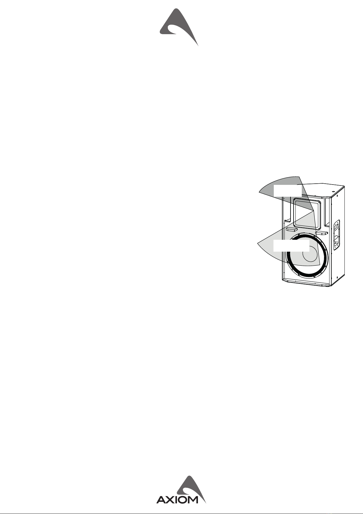
enclosure, designed for many mul-purpose sound reinforcement acvies. The asymmetric HF
coverage paern, varying from 100° horizontal in the lower part of the horn for more eecve
near eld coverage, and narrowing to 60° horizontal at the top of the horn for more focused
coverage in the far eld. The result is more accurate coverage of a typical auditorium than is
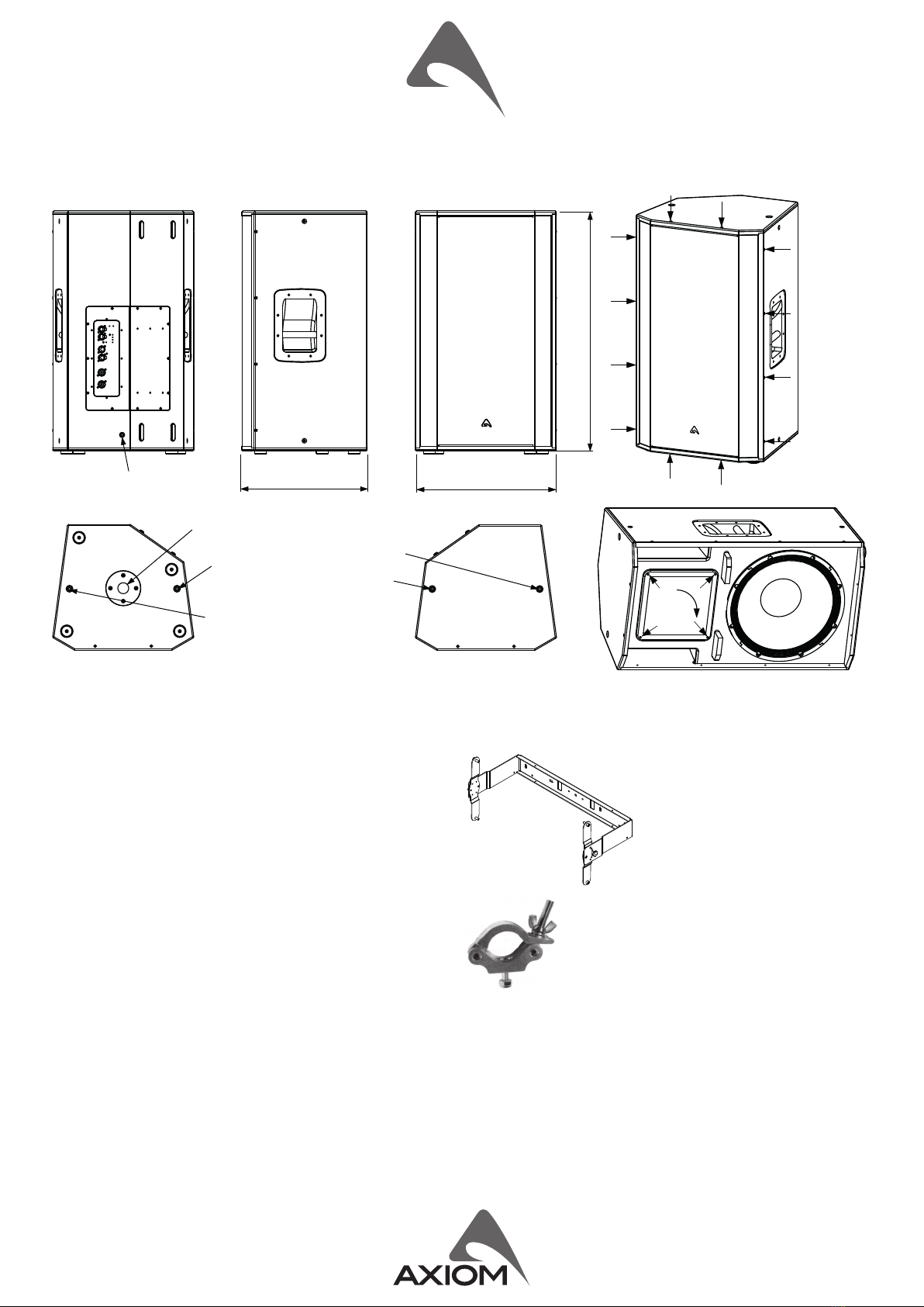
possible with a xed horizontal coverage device. The HF horn is also rotatable through 90° by
simply removing four screws and realigning the horn, so that coverage can also be opmised
for stage monitor use. This rotatable horn feature also makes it possible to maintain the ideal
coverage paern when the cabinet is installed in a horizontal (landscape) orientaon. Its
asymmetric dispersion paern provides opmal coverage of typical rectangular venues, with
wider dispersion at the front and narrower dispersion at the rear.
This versale loudspeaker can also be used as a low prole stage monitor with its 35° tapered
side, and in this situaon the HF horn can be rotated to maintain the best coverage paern for
performers both near to and further away from the monitor. ED150A cabinet is an unobtrusive
and compact format designed for a multude of near eld applicaons such as theatre under-
balcony ll, stage front ll, delay speaker, bar and restaurant audio, and discreet stage monitor.
A pole mount socket make this a very versale loudspeaker in both portable and permanently
installed applicaons.
TECHNICAL SPECIFICATION
SYSTEM Remote Controls PRONET control soware
System’s Acousc Principle Two-way Vented Enclosure
Asymmetric Dispersion
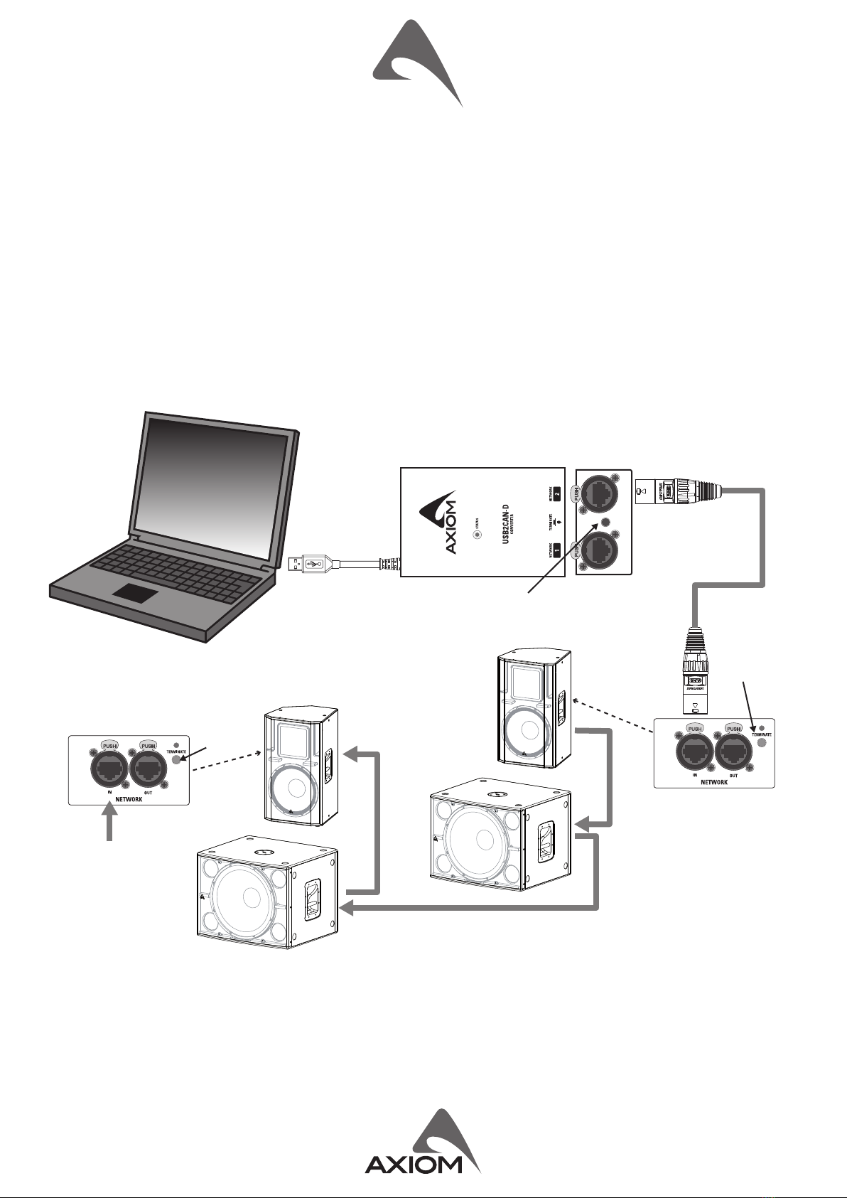
Network protocol CANBUS
Amplier Type Class D amplier with SMPS
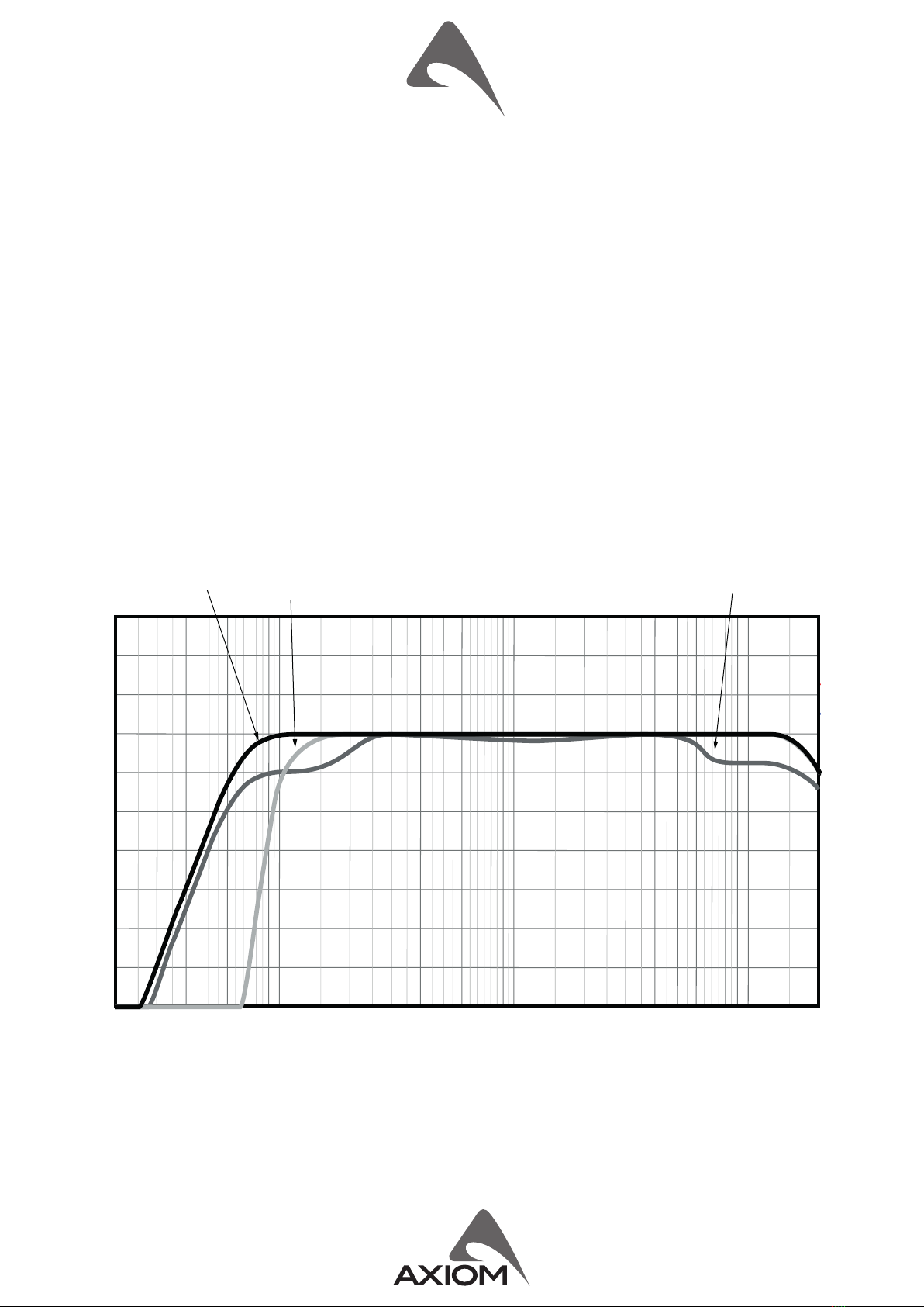
Frequency response 50 Hz – 17 kHz (-6dB Processed) Output Power 900W + 300W
Horizontal Coverage Angle 60 to 100° (-6 dB) Mains Voltage Range (Vac) 220-240V~ or 100-120V~ ±10% 50/60Hz
Vercal Coverage Angle 60°, 1KHz to 17KHz (-6dB) Consumpon* 575 W (nominal) 1200 W (max)
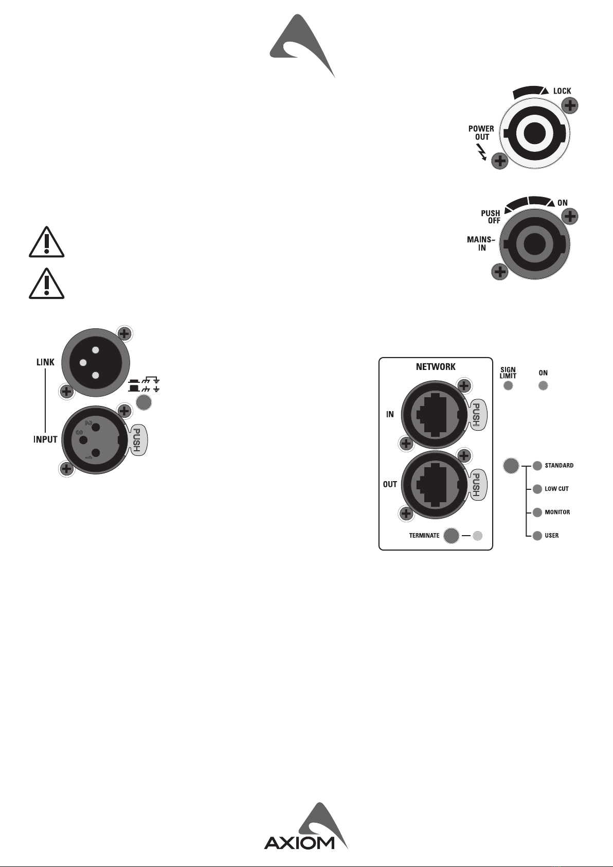
Maximum Peak SPL @ 1m 128 dB IN / OUT Connectors Neutrik XLR-M / XLR-F
TRANSDUCERS IN / OUT Network Connectors ETHERCON® (NE8FAV)
Low frequency transducer 15” (300 mm), 3” (75 mm) ISV
aluminium voice coil, 4Ω
Mains Input/Link Connectors PowerCon® (NAC3MPXXA+NAC3MPXXB)
Cooling Variable speed DC fan
High frequency transducer
1.4” (35.5 mm) compression driver, 2.4”
(60 mm) aluminium voice coil, Titanium
diaphragm, 8Ω
ENCLOSURE & CONSTRUCTION
Width 450 mm (17.7”)
Height 765 mm (30.1”)
ELECTRICAL Depth 400 mm (15.8”)
Input Impedance 20 kΩ balanced Taper angle Stage Monitor: 35° - Fronill: 7.5°
Input Sensivity +4 dBu / 1.25 V Enclosure Material 15mm, reinforced phenolic birch
Signal Processing
CORE2 processing, 40bit oang
point SHARC DSP, 24 bit AD/DA
converters
Paint High resistance, black or white water
based paint
Flying System M10 ying points or dedicated metal
brackets
Direct access Controls
4 Presets:
Standard, Low Cut, Monitor, User.
Network Terminaon, GND Link
Net Weight 31 Kg (68.3 lbs)
* Nominal consumpon is measured with pink noise with a crest factor of 12 dB, this can be considered a standard music program.
h100°
h60°
INDEX
INTRODUCTION ...........................4
TECHNICAL SPECIFICATION ..................4
MECHANICAL DRAWING ....................5
OPTIONAL ACCESSORIES ....................5
SPARE PARTS ..............................5
I/O AND CONTROL OPERATIONS ..............6
MAINS IN .................................6
MAINS OUT ...............................6
INPUT ...................................6
LINK .....................................6
ON ......................................6
SIGN/LIMIT ...............................6
GND LIFT .................................6
NETWORK IN/OUT .........................6
TERMINATE ...............................6
PRESET BUTTON ...........................7
PRONET AX ...............................8
HORN ORIENTATION .......................10
KPTED150B WALL or TRUSS MOUNTING .......11

5
MECHANICAL DRAWING
OPTIONAL ACCESSORIES
KPTED150B Wall or Truss Mounng “C” bracket.
PLH300 Ø 48-51mm truss tube aluminium coupler with
M12 x 50 built-in bolt and fastening nut.
NAC3FCA Neutrik Powercon® BLUE PLUG NC3MXXBAG Neutrik XLR-M
NAC3FCB Neutrik Powercon® WHITE PLUG NC3FXXBAG Neutrik XLR-F
NE8MCB Neutrik Ethercon PLUG USB2CAN-D PRONET network converter
see hp://www.axiomproaudio.com/ for detailed descripon and other available accessories.
SPARE PARTS
NAC3MPA Neutrik Powercon® BLUE SOCKET 98NEOS15SW4 15’’ woofer - 3” VC - 4 ohm
NAC3MPB Neutrik Powercon® WHITE SOCKET 98DRI2065 1.4’’ - 2.4” VC compression driver - 8 ohm
91AMDED150A Power amplier module with mechanical
assembly
98MBN2065 tanium diaphragm for 1.4” driver
2) Unscrew the 4 screws fixing the horn and
rotate the horn by 90°.
turn
90°
INSTRUCTION FOR ROTATING THE HORN
1) Remove the speaker grid unscrewing
the twelve screws indicated below.
40 cm
15.8"
45 cm
17.7"
76.5 cm
30.1"
M10 Flying Point
Pole Adapter
M10 Flying Point
M10 Flying Point
M10 Flying Point
M8 Aiming Point

6
I/O AND CONTROL OPERATIONS
MAINS IN
Powercon® NAC3FCA power input connector (blue). To switch the amplier on, insert the Powercon®
connector and turn it clockwise into the ON posion. To switch the amplier o, pull back the switch
on the connector and turn it counter-clockwise into the POWER OFF posion.
MAINS OUT
Powercon® NAC3FCB power output connector (grey). This is connected in parallel with the MAINS
~ / IN. The maximum load applicable depends on the mains voltage. With 230V~ we suggest to
link a maximum of 5 ED120A loudspeakers, with 120V~ we suggest to link a maximum of 3 ED120A
loudspeaker.
WARNING! In the case of product failure or fuse replacement, disconnect the unit
completely from the mains power. The power cable must only be connected to a socket
corresponding to the specicaons indicated on the amplier unit.
The power supply must be protected by a suitably rated thermo-magnetic breaker.
Preferably use a suitable switch to power on the whole audio system leaving the Powercon®
always connected to each speaker, this simple trick extend the life of the Powercon®
connectors.
INPUT
Audio signal input with locking XLR connector. It has a fully electronically balanced circuitry
including AD conversion for the best S/N rao and input headroom.
LINK
A direct connecon from the input connector to
link other speakers with same audio signal.
ON
This LED indicates power on status.
SIGN/LIMIT
This LED lights in green to indicate the presence
of the signal and lights in red when an internal
limiter reduces the input level.
GND LIFT
This switch li the ground of the balanced audio inputs from the earth-ground
of the module.
NETWORK IN/OUT
These are a standard RJ45 CAT5 connectors (with oponal NEUTRIK NE8MC RJ45 cable connector carrier), used for PRONET network
transmission of remote control data over long distance or mulple unit applicaons.
TERMINATE
In a PRONET network the last loudspeaker device must be terminated (with an inner load resistance) especially in a long run cabling:
press this switch if you want to terminate the unit.

7
PRESET BUTTON
This buon has two funcon:
1) Pressing it while powering on the unit:
ID ASSIGN the internal DSP assigns a new ID to the unit for the PRONET AX remote control operaon. Each loudspeaker must
have a unique ID to be visible in the PRONET network. When you assign a new ID, all the other loudspeakers with
the ID already assigned must be ON and connected to the network.
2) Pressing it with the unit ON you can select the DSP PRESET. The selected PRESET is indicated by the corresponding LED:
STANDARD Suited for a typical use of a standalone loudspeaker for any sound reinforcement situaon.
LOW CUT This PRESET is the same of the previous with an high pass lter (110Hz @ 48 dB/oct.) to use the loudspeaker in
combinaon with a subwoofer.
MONITOR Suited for the use of the system as a stage monitor, in this preset the deep lows are aenuated in order to
compensate the oor poson, the mid-low frequencies are enhanced for a beer presence and the mid-high
frequencies are reduced for an improved feedback rejecon.
USER This LED lights when the USER PRESET is loaded. This preset corresponds to USER MEMORY no. 1 of the DSP and,
as a factory seng, it’s the same to STANDARD. If you want to modify it, you have to connect the unit to a PC, edit
the parameters with PRONET AX soware and save the PRESET into USER MEMORY no. 1.
Note: see also the PRONET example further on this manual.
+15 dB
+10
+5
0
-5
-10
-15
-20
-25
-30
-35 20 50 100 200 500 1K 2K 5K 10K 20K Hz
MONITORSTANDARD LOW CUT
ED150A - PRESET RESPONSE

8
PRONET AX
PRONET AX soware has been developed in collaboraon with sound engineers and sound designers, in order to oer an “easy-to-
use” tool to setup and manage your audio system. With PRONET AX you can visualize signal levels, monitor internal status and edit
all the parameters of each connected device.
Download the PRONET AX app registering on MY AXIOM at the website at hps://www.axiomproaudio.com/.
The AXIOM acve loudspeaker devices can be connected in a network and controlled by the PRONET AX soware, for the network
connecon the USB2CAND converter oponal accessory is needed.
PRONET AX network is based on a “bus-topology” connecon, where the rst device is connected to the network input connector
of the second device, the second device network output is connected to the network input connector of the third device, and so
on. To ensure a reliable communicaon the rst and the last device of the “bus-topology” connecon must be terminated. This can
be done by pressing the “TERMINATE” switch near the network connectors in the rear panel of the rst and the last device. For
the network connecons simple RJ45 cat.5 or cat.6 ethernet cables can be used (please don’t confuse a ethernet network with a
PRONET AX network these are completely dierent and must be fully separated also both use the same kind of cable).
USB2CAND
do not
pressed
pressed
LAST DEVICE
network
network
FIRST DEVICE
AND FOLLOWING
notebook
with PRONET AX so�ware
USB 2.0 port
1) pressed if the USB2CAND is the first device
2) not pressed if other AXIOM system is connected
to the other connector
EXAMPLE OF PRONET NETWORK WITH ED120A/150A AND SW18A

9
Assign the ID number
To work properly in a PRONET AX network each connected device must have a unique idener number, called ID. By default the
USB2CAN-D PC controller has ID=0 and there can be only one PC controller. Every other device connected must have its own unique
ID equal or greater than 1: in the network cannot exist two devices with the same ID.
In order to correctly assign a new available ID to each device for working properly in a Pronet AX network, follow these instrucons:
1. Switch o all the devices.
2. Connect them correctly to the network cables.
3. “TERMINATE” the end device in the network connecon.
4. Switch on the rst device keep pressed “PRESET” buon on the control panel.
5. Leaving the previous device switched on, repeat the previous operaon on the next device, unl the latest device is turned on.
The “Assign ID” procedure for a device makes the internal network controller to perform two operaons: reset the current ID; search
the rst free ID in the network, starng from ID=1. If no other devices are connected (and powered on), the controller assume ID=1,
that is the rst free ID, otherwise it searches the next one le free.
These operaons ensure that every device has it’s own unique ID, if you need to add a new device to the network you simply repeat
the operaon of step 4. Every device maintains its ID also when it is turned-o, because the idener is stored in the internal
memory and it is cleared only by another “Assign ID” step, as explained above.
With the network made always of the same devices the assigning ID procedure must be executed only the rst me
the system is turned on.
For more detailed instrucon about PRONET see the PRONET AX USER’S MANUAL included with the soware.

10
HORN ORIENTATION
ED150A features an asymmetrical horn that can be rotated in a few minutes for obtaingn the best coverage according to the speaker
conguraon.
WARNING! CAREFULLY READ THE FOLLOWING INSTRUCTIONS AND CONDITION OF USE:
• For a supplementary safety assure always the loudspeaker to the wall with an alternave rope.
• This loudspeaker is designed exclusively for Professional audio applicaons. The product must be installed by qualied
personal only.
• Proel strongly recommends that this loudspeaker cabinet be suspended taking into consideraon all current Naonal,
Federal, State and Local regulaons. Please contact the manufacturer for further informaon.
• Proel do not accept any liability for damage caused to third pares due to improper installaon, lack of maintenance,
tampering or improper use of this product, including disregard of acceptable and applicable safety standards.
• During assembly pay aenon to the possible risk of crushing. Wear suitable protecve clothing. Observe all
instrucons given on the rigging components and the loudspeaker cabinets. When chain hoists are in operaon ensure
that there is nobody directly underneath or in the vicinity of the load. Do not under any circumstances climb on the array.
wide dispersion
short throw
HORIZONTAL POSITION
STAGE MONITOR CONFIGURATION
Tight dispersion
long throw
HORIZONTAL POSITION
FOH CONFIGURATION
wide dispersion
short throw
Tight dispersion
long throw
VERTICAL POSITION
FOH CONFIGURATION
Tight dispersion
long throw
wide
dispersion
short throw

11
KPTED150B WALL or TRUSS MOUNTING
Using the “C” shape bracket the ED150A loudspeaker can be installed to walls or mounted to trusses in combinaon combining
with two PLH300.
It allows to aim the speaker in one direcon (vercal or horizontal) in 21 steps (0°, ±5°, ±10°, ±15°, ±25°, ±30°, ±40°, ±45°, ±55°,
±70°, ±85°).
For installing the speaker using the “C” bracket follow these instrucons:
1) Install the “C” bracket to the the wall or to the truss.
2) Mount the two rotaon brackets on the top and boom of the loudspeker using the bolts (a).
3) Carefully put the loudspeaker into the “C” bracket then screw in the screws (b) to x it to the “C” bracket.
4) Aim the loudspeaker and ghten the screw-knobs (c) in the desired holes.
5) Tight the screws (b).
2
a
a
a
a
1
2
2
2
c
c
b
b
4
4
3
3
5
5

PROEL S.p.A. (World Headquarters) - Via alla Ruenia 37/43 - 64027 Sant’Omero (Te) - ITALY
Tel: +39 0861 81241 Fax: +39 0861 887862 www.axiomproaudio.com
Other manuals for ED150A
1
Table of contents
Other Axiom Speakers manuals

Axiom
Axiom AX6C User manual

Axiom
Axiom Architectural W2 User manual

Axiom
Axiom LFR660 v4 User manual

Axiom
Axiom FMS 16/24 Specification sheet

Axiom
Axiom ED23PMKII User manual

Axiom
Axiom AX2010A User manual

Axiom
Axiom LFR1100 User manual

Axiom
Axiom AX2065A User manual

Axiom
Axiom Architectural W100 User manual

Axiom
Axiom AX4CL User manual

Axiom
Axiom Architectural Series W100 Specification sheet

Axiom
Axiom ED80P User manual

Axiom
Axiom M2 User manual

Axiom
Axiom W2 Specification sheet

Axiom
Axiom VP100 v2 User manual

Axiom
Axiom M3 User manual

Axiom
Axiom ED150A User manual

Axiom
Axiom M2 User manual

Axiom
Axiom M100 User manual

Axiom
Axiom AX12LF User manual