Axioma QALCOSONIC W1 Parts list manual

wwwwW
QALCOSONIC W1
TECHNICAL DESCRIPTION,
INSTALLATION MANUAL
AND USER GUIDE
AXIOMA METERING UAB
ULTRASONIC WATER
METER QALCOSONIC W1
PE_QW1_V07

TABLE OF CONTENTS
SAFETY INFORMATIO
1 APPLICATION FIELD
2 TECHNICAL DATA
2.1 DISPLAY LCD
2.2 DATA RECORDING AND STORAGE
2.3 ALARMS
2.4 EXTERNAL COMMUNICATION MODULES AND INTERFACES
2.5 PULSE OUTPUTS IN TEST MODE
2.6 POWER SUPPLY
2.7 MECHANICAL DATA
2.8 OPERATION CONDITIONS
3 OPERATING PRINCIPLE
4 MARKING AND SEALING
4.1 MARKING
4.2 SEALING
5 INSTALATTION
5.1 GENERAL REQUIREMENTS
5.2 CHECKING CONFIGURATION OF THE METER
5.3 MOUNTING
5.4 CHECKING OF INSTALLATION AND PARAMETER SETTING
6 OPERATION
6.1 DISPLAY FUNCTIONS
6.2 MENU STRUCTURE
6.3 VIEWING THE READINGS IN NORMAL MODE USER MENU
6.4 VIEWING THE READINGS IN VERIFICATION TEST MODE
6.5 VOLUME READINGS IN VERIFICATION MODE
6.6 INFO STATUS CODES
6.7 VERIFICATION TEST MODE CONTROL
6.8 ENDING OF VERIFICATION MODE
7 VERIFICATION
8 TRANSPORTATION AND STORAGE REQUIREMENTS
ANNEX A
A.1 DN 20:
A.2 DN 15:
ANNEX B
WARRANTY
3
3
5
6
6
7
7
8
8
8
8
8
9
9
9
9
9
9
10
10
10
10
11
12
13
13
13
14
14
14
14
15
15
16
17
18

axiomametering.com 3
Marking of electrical and
electronic equipment in
accordance with Article 14
(2) of Directive 2012/19/EU
It is prohibited to dispose a
meter marked with this sign
For EU Customers only - WEEE Marking
EU DECLARATION OF CONFORMITY
AXIOMA Metering UAB, Veterinarų g. 52, Biruliškių k., Kauno raj., Lithuania, hereby declares that the water meter QALCOSONIC W1
conforms to the essential requirements of the following Directives:
2014/32/EU Directive 2014/32/EU of the
European Parliament and of the Council
of 26 February 2014 on the harmonisation
of the laws of the Member States relating
to the making available on the market of
measuring instruments (recast).
2014/30/EU Directive 2014/30/EU of the
European Parliament and of the Council of
26 February 2014 on the harmonisation of
the laws of the Member States relating to
electromagnetic compatibility (recast).
2014/35/EU Directive 2014/35/EU of the
European Parliament and of the Council
of 26 February 2014 on the harmonisation
of the laws of the Member States relating
to the making available on the market of
electrical equipment designed for use wi-
thin certain voltage limits.
2014/53/EU Directive 2014/53/EU of the
European Parliament and of the Council
of 16 April 2014 on the harmonisation of
the laws of the Member States relating to
the making available on the market of ra-
dio equipment.
Kaunas, 31/01/2020
EU-Type Examination Certificate No: LT-1621-MI001-034
Quality System Certificate No: KS-1621-MP-003.18
The Notified Body:
Laboratory of Heat Equipment Research and Testing of the Lithuanian Energy Institute, Lithuania, Notified Body Number 1621.
into an unsorted municipal waste container
together with other waste!
This symbol on the product indicates that
it will not be treated as household waste. It
must be handed over to the applicable ta-
ke-back scheme for the recycling of elec-
trical and electronic equipment. For more
detailed information about the recycling of
this product, please contact your local mu-
nicipal oce
Before beginning of installation works you
must to read this document and follow its
instructions.
The meter is battery-powered (3.6 V),
risk factors during the meter installation
and service fluid flowing within flow sen-
sor with inner pressure up to 1,6 MPa and
temperature up to 90°C.
• Only qualified technical personnel
may install and maintain water me-
ters. Personnel must be familiar with
appropriate technical documentati-
on and general safety instructions. It
is necessary to follow general safety
requirements during installation and
maintenance process.
• Safety guarantees at installation and
service of meter is:
- Hermetic fitting of primary flow sen-
sor into the pipeline,
- Reliable fastening of water meter at
installation.
SAFETY INFORMATION
• The meter can be used at ambient
temperature: -15°C ... +70°C
WARNING!
Mounting of the sub-assemblies of water meter is permissible only after ensuring of absence of fluid and pressure in the pipeline.
CAUTION:
If this equipment is used in a manner not specified by the manufacturer, the protection provided by the equipment may be impaired.
• Storage and transportation temperatu-
re: -25°C ... +70°C (drained flow part)
1 APPLICATION FIELD
Ultrasonic water meter QALCOSONIC W1 is designed for measurement of cold and hot water consumption.
The meter corresponds to essential
requirements of the Technical Regulation
requirements Annexes I and MI 001. The
meter complies with the requirements
of European Standards EN ISO 4064
and requirements of OIML R49-1.
CLIMATIC ENVIRONMENTAL
CONDITIONS:
Temperature range: from -15°C to +70°C
Humidity: condensing
Mechanical environment class: M1
Electromagnetic environment class: E2

axiomametering.com 4
ORDERING CODE COMBINATION OF THE METER *:
Meter QALCOSONIC W1 QW1
THE RATIO R Q3/Q1: CODE
250 1
315 2
400 3
800 4
Type
_ _ _ _ _ _
PERMANENT FLOW
RATE Q3, M3/H
OVERALL
LENGTH L, MM
END
CONNECTIONS CODE
1,6 80 G ¾ 11
1,6 105 G ¾ 12
1,6 110 G ¾ 13
1,6 165 G ¾ 14
1,6 170 G ¾ 15
2,5 80 G ¾ 21
2,5 105 G ¾ 22
2,5 110 G ¾ 23
2,5 165 G ¾ 24
2,5 170 G ¾ 25
2,5 105 G1 31
2,5 110 G1 32
2,5 130 G1 33
2,5 165 G1 34
2,5 190 G1 35
4 105 G1 41
4 110 G1 42
4 130 G1 43
4 165 G1 44
4 190 G1 45
COMMUNICATION INTERFACE TYPE: CODE
RF 868 MHz 0
RF 433 MHz 1
RF 915 MHz 2
RF 920,5 MHz 3
NB - IoT 4
COMMUNICATION PROTOCOL: CODE
S1 1x
T1 2x
C1 3x
LORA WAN X1
SIGFOX X2
EXTRA COMMUNICATION INTERFACE: CODE
NONE 0
TEMPERATURE CLASS: CODE
Temperature class T 30 1
Temperature class T 30/90 2
Temperature class T 90 3
Temperature class T 50 4

axiomametering.com 5
PERMANENT
FLOW RATE
Q
3
, M
3
/H
RATIO R
Q3/Q1
OVERLOAD
FLOW RATE
Q
4
, M
3
/H
MINIMUM
FLOW RATE
Q
1
, M
3
/H
TRANSITIONAL
FLOW RATE
Q
2
, M
3
/H
THRESHOLD
VALUE,
M
3
/H
JOINING
TO THE
PIPELINE
(THREAD – G)
OVERALL
LENGTH L,
MM
PRESSURE
LOSS
CLASS ΔP
(BAR X 100)
1,6 250 2 0,0064 0,010 0,001 G ¾ 80 Δp 25
1,6 250 2 0,0064 0,010 0,001 G ¾ 105 Δp 25
1,6 250 2 0,0064 0,010 0,001 G ¾ 110 Δp 25
1,6 250 2 0,0064 0,010 0,001 G ¾ 165 Δp 25
1,6 250 2 0,0064 0,010 0,001 G ¾ 170 Δp25
1,6 315 2 0,005 0,008 0,001 G ¾ 80 Δp25
1,6 315 2 0,005 0,008 0,001 G ¾ 105 Δp25
1,6 315 2 0,005 0,008 0,001 G ¾ 110 Δp25
1,6 315 2 0,005 0,008 0,001 G ¾ 165 Δp25
1,6 315 2 0,005 0,008 0,001 G ¾ 170 Δp25
1,6 400 2 0,004 0,0064 0,001 G ¾ 80 Δp25
1,6 400 2 0,004 0,0064 0,001 G ¾ 105 Δp25
1,6 400 2 0,004 0,0064 0,001 G ¾ 110 Δp25
1,6 400 2 0,004 0,0064 0,001 G ¾ 165 Δp25
1,6 400 2 0,004 0,0064 0,001 G ¾ 170 Δp25
2,5 250 3,125 0,01 0,016 0,001 G ¾ 80 Δp40
2,5 250 3,125 0,01 0,016 0,001 G ¾ 105 Δp40
2,5 250 3,125 0,01 0,016 0,001 G ¾ 110 Δp40
2,5 250 3,125 0,01 0,016 0,001 G ¾ 165 Δp40
2,5 250 3,125 0,01 0,016 0,001 G ¾ 170 Δp40
2,5 400 3,125 0,0062 0,010 0,001 G ¾ 80 Δp40
2,5 400 3,125 0,0062 0,010 0,001 G ¾ 105 Δp40
2,5 400 3,125 0,0062 0,010 0,001 G ¾ 110 Δp40
2,5 400 3,125 0,0062 0,010 0,001 G ¾ 165 Δp40
2,5 400 3,125 0,0062 0,010 0,001 G ¾ 170 Δp40
2,5 800 3,125 0,0031 0,005 0,001 G ¾ 80 Δp40
2,5 800 3,125 0,0031 0,005 0,001 G ¾ 105 Δp40
2,5 800 3,125 0,0031 0,005 0,001 G ¾ 110 Δp40
2,5 800 3,125 0,0031 0,005 0,001 G ¾ 165 Δp40
2,5 800 3,125 0,0031 0,005 0,001 G ¾ 170 Δp40
2,5 250 3,125 0,01 0,016 0,001 G1 105 Δp25
2,5 250 3,125 0,01 0,016 0,001 G1 110 Δp25
2,5 250 3,125 0,01 0,016 0,001 G1 130 Δp25
2,5 250 3,125 0,01 0,016 0,001 G1 165 Δp25
2,5 250 3,125 0,01 0,016 0,001 G1 190 Δp25
2,5 400 3,125 0,0062 0,010 0,001 G1 105 Δp25
2,5 400 3,125 0,0062 0,010 0,001 G1 110 Δp25
2,5 400 3,125 0,0062 0,010 0,001 G1 130 Δp25
2,5 400 3,125 0,0062 0,010 0,001 G1 165 Δp25
2,5 400 3,125 0,0062 0,010 0,001 G1 190 Δp25
4 250 5 0,016 0,025 0,002 G1 105 Δp40
4 250 5 0,016 0,025 0,002 G1 110 Δp40
4 250 5 0,016 0,025 0,002 G1 130 Δp40
4 250 5 0,016 0,025 0,002 G1 165 Δp40
4 250 5 0,016 0,025 0,002 G1 190 Δp40
4 400 5 0,01 0,016 0,002 G1 105 Δp40
4 400 5 0,01 0,016 0,002 G1 110 Δp40
4400 5 0,01 0,016 0,002 G1 130 Δp40
4 400 5 0,01 0,016 0,002 G1 165 Δp40
4 400 5 0,01 0,016 0,002 G1 190 Δp40
4 800 5 0,005 0,008 0,002 G1 105 Δp40
4 800 5 0,005 0,008 0,002 G1 110 Δp40
4 800 5 0,005 0,008 0,002 G1 130 Δp40
4 800 5 0,005 0,008 0,002 G1 165 Δp40
4 800 5 0,005 0,008 0,002 G1 190 Δp40
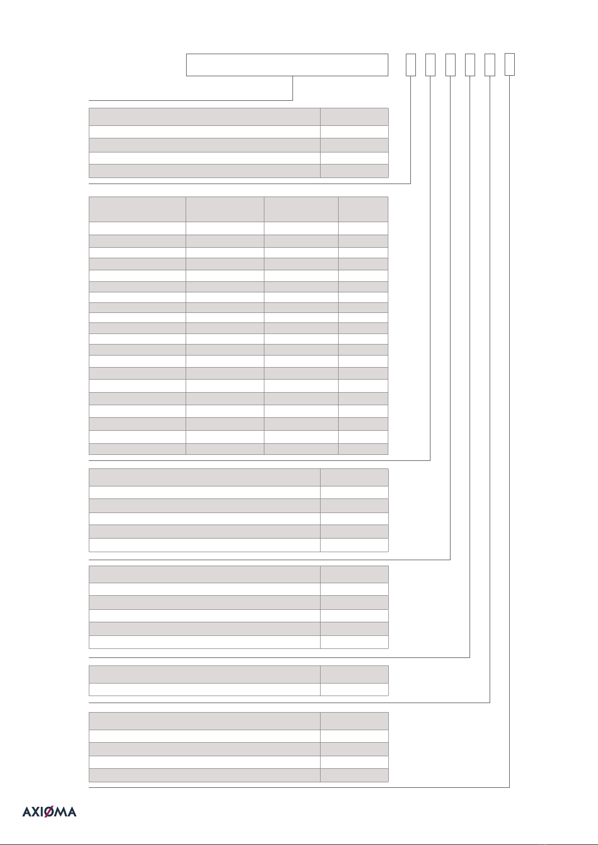
2 TECHNICAL DATA
Ratio of the permanent flow rate to the lower limit of the flow-rate (selectable by the user):
Q
3
/Q
1
= 250 , Q
3
/Q
1
= 315, Q
3
/Q
1
= 400, Q
3
/Q
1
= 800
The technical data of the meter are provided in Table 1.1.
1.1. Table

axiomametering.com 6
WORKING TEMPERATURE RANGE:
Meter temperature class T30 (0,1°C ... 30°C)
Meter temperature class T50 (0,1°C ... 50°C)
Meter temperature class T30/90 (30°C ... 90°C)
Meter temperature class T90 (0,1°C ... 90°C)
•Maximum admissible working pressure (pressure class) 16 bar (MAP16)
•Flow profile sensitivity class U0 D0
•Volume measurement units m
3
•Resolution of a displaying device 0,001 m
3
•Displaying range 999999,999 m
3
The maximum permissible error (MPE) on volumes delivered at flow rate between the transitional flow rate Q
2
(included) and
the overload flow rate Q4(included) is:
•When water temperature ≤ +30 °C 2 %
•When water temperature > +30 °C 3 %
The maximum permissible error (MPE) on volumes delivered at flow rate between the minimum flow rate Q
1
(included) and the
transitional flow rate Q
2
(excluded) for water having any temperature is: 5%
If the flow-rate exceeds the maximum value Q
4
:
•When the flow-rate Q ≤ 1.2 · Q
4
, the flow-rate measurement and calculations are continued.
•When the flow-rate Q > 1.2 · Q
4
, calculations are performed using flow-rate value 1.2 · Q
4
and the info code
“Maximum allowed value of flow rate is exceeded” is recorded and the duration of that status is calculated.
+
_
+
_
+
_
2.1 DISPLAY LCD
THE DEVICE IS EQUIPPED WITH 2LINES LCD LIQUID CRYSTAL DISPLAY:
Upper line with 9-digits for displaying measured volume of water:
•Readings in normal mode: m3 ( three digits after decimal point).
•Readings in verification (TEST) mode: m3 (six digits after decimal point).
Lower line with 5-digits for displaying current flow rate in m3/h and special symbols for displaying operation modes. In the
case of battery discharge, all integral readings and archive data shall be saved for at least 16 years and can be accessed by
connecting a power battery in the operating condition.
2.2 DATA RECORDING AND STORAGE
In its memory, meter accumulates an archive of hourly, daily, and monthly measured parameters. Archive data can be read only by
remote data reading means, mentioned in 2.4 paragraph. Data archive values, which are also additionally showed on the display, are
specified in Paragraph 6.4.
1Integral volume of water
2 Integral volume of water in the forward direction
3 Informational flow in the reverse direction
4 Maximum flow rate value and date
5 Info (Status) code
6 Total operating time
7 Operating time without error
8 Temperature
THE FOLLOWING PARAMETERS OF EACH HOUR, DAY, AND MONTH ARE ACCUMULATED IN THE MEMORY OF THE METER:

axiomametering.com 7
DATA LOGGER CAPACITY:
•Up to 1480 hours for hourly records.
•Up to 1130 days for daily records.
•Up to 36 last months for monthly records.
Archive data storage time not less than 36 months. Storage time of measured integrated parameters even if device is disconnec-
ted from power supply is not less than 16 years.
2.3 ALARMS
Qalcosonic W1 meter has integrated system that informs about certain alarms. Several of them are critical and being
transmitted immediately. Other alarms or events are logged in status byte and transmitted within data telegrams.
BY DEFAULT ENABLED CRITICAL ALARMS (SINCE 2020.06.01):
•Leakage (occurs when constant flow rate within 24 hours is more than 0.25/0.5/1% of Q3.
Disappears after 1 hour, if constant flow rate within that hour is less than configured value).
•Burst (occurs when constant flow rate within 60 minutes is more than 5/10/20% of Q3.
Disappears after 32 seconds, if constant flow rate within that period of time is less than configured value).
•Freeze (occurs when water temperature reaches about 2/3/4/5°C).
•Tamper (occurs when meter is opened or damaged).
BY DEFAULT DISABLED CRITICAL ALARMS:
•Negative flow (occurs when meter detects negative flow).
•No consumption (occurs when there was no water for the last 3/7/30 days).
All these critical errors are also shown in status byte. It also might show indications of empty pipe, communication credits, battery
lifetime and other.
2.4 EXTERNAL COMMUNICATION MODULES AND INTERFACES
AVAILABLE COMMUNICATION MODULES FOR DATA TRANSMISSION (ONLY ONE OPTION MIGHT BE SELECTED WHEN
PLACING THE ORDER):
•RF 868 MHz
•RF 433 MHz
•RF 915 MHz
•RF 920,5 MHz
•NB-IoT (frequency bands B1, B3, B5, B8, B20, B28)
DATA IN QALCOSONIC W1 METER CAN BE TRANSMITTED USING THE FOLLOWING PROTOCOLS:
•wMBus T1
•wMBus S1
•wMBus C1
•SIGFOX
•LORA WAN
•CoAP
All communication interfaces are intend-
ed for data reading and meter parametri-
sation. The meter is produced for being
powered only from the internal battery. In
order to save the battery, communication
credit system is implemented into the
meter. Time of communication through
additional interfaces is automatically lim-
ited to save the battery (up to 20 minutes
per month). Unused communication limit
is summed up. If the limit is expired, the
interface is blocked and the new time
limit of communications will start only af-
ter the change of the hour (16 seconds for
each next hour).
Optical interface is integrated in Qal-
cosonic W1 meter by default. It is intend-
ed for data reading, changing parameters
of meter and for outputting optical pulses
in the test (verification) mode. It is activat-
ed by sending 1 second pulse sequence (5
minutes after the end of communication
is automatically deactivated).
There is also NFC (Near Field Communi-
cation) interface integrated by default. It is
intended for data reading only.

axiomametering.com 8
2.5 PULSE OUTPUTS IN TEST MODE
Pulse values are available only in Test Mode and it depends on the nominal flow rate Q
3
. It is specified in the table below:
Permanent flow rate, Q3, m3/h 1,6 2,5 4,0
Pulse value, m3/imp 0,001 0,002 0,004
END CONNECTIONS OVERALL LENGTH WEIGHT OF METER, NOT MORE THAN, KG
G3/4“ (80 mm) 0,3
G3/4“ (105 mm) 0,3
G3/4“ (110 mm) 0,3
G3/4“ (165 mm) 0,3
G3/4“ (170 mm) 0,3
G1“ (105 mm) 0,4
G1“ (110 mm) 0,4
G1“ (130 mm) 0,4
G1“ (165 mm) 0,4
G1“ (190 mm) 0,4
2.6 POWER SUPPLY
Meter is powered with one or two internal AA-size 3.6V lithium (Li-SOCl2) batteries with a service life of at least 16 years. Batteries
cannot be replaced. Accurate battery lifetime depends also on data transmission frequency.
2.7 MECHANICAL DATA
Dimensions of Qalcosonic W1 water meter are not greater than 75 mm x 77 mm x 190 mm (DN20, L190).
WEIGHT OF DIFFERENT SIZES OF QALCOSONIC W1 WATER METERS ARE SHOWN IN THE TABLE BELOW:
2.8 OPERATION CONDITIONS
Enclosure protection class: IP68
OPERATING CONDITIONS:
•ambient temperature form -15°C
to 70°C
•relative humidity up to 100%,
condensing
•atmospheric pressure 86 kPa to
106.7 kPa
Installation: Indoor or outdoor
Mechanical environment class: M1
Electromagnetic environment class: E2
3 OPERATING PRINCIPLE
WATER METER PERFORMS ALL NECESSARY MEASUREMENT AND DATA STORAGE FUNCTIONS.
BELOW ARE THE MOST IMPORTANT:
•High stability in measuring water volume and detection characteristics of overload
•Calculation of the maximum values and their storage in archive
•Storage of necessary data for reports on set day yearly and monthly
•Archive data storage time 36 months
•Detection of faults
•Displaying values of parameters (optional) and displaying info codes
•Verification and service functions
Flow measuring principle is based on
ultrasonic measurement method. Ultra-
sonic signal moves along the measuring
section many times and the flow down-
stream between the ultrasonic sensors
have to perform transmitter and receiver
functions. From the results of time dier-
ence the flow rate is calculated and indi-
cated in display.

axiomametering.com 9
4 MARKING AND SEALING
THE FOLLOWING IS INDICATED ON THE HOUSING OF WATER METER:
•Type of connection (thread or relative diameter)
•Flow direction
There is following information on the front
panel of the calculator of the meter: EC-
type examination certificate number, man-
ufacturer’s trade mark, distributor logo (if
applicable), type of meter, year of manu-
facture and serial number, permanent flow
rate Q3 and ratio R (Q3/Q1), temperature
class, maximum admissible working pres-
sure (MAP), pressure loss class, installation
sensitivity class of the meter, latest date by
witch the meter shall be replaced, software
version number, IP code, communication
interface NB-IoT (if installed on the meter).
4.1 MARKING
4.2 SEALING
The meter casing is imperceptibly closed.
Any unautorized opening of the housing
is impossible without damaging. Addi-
tional manufacturer protection is not ap-
plied. The manufacturers warranty does
not apply if the upper cover is opened or
connection between upper cover and the
housing is damaged.
When the upper sealed cover is opened,
the safety button that installed in the meter
body is activated and error code appears
on the meter display.
For sealing of meter after installation, there
are provided holes in the meter body (See
Annex B).
5 INSTALATTION
PRIOR TO INSTALLING THE METER, IT IS NECESSARY:
•to check the complete set of the meter with that specified in the technical documentation.
•to check for any visible mechanical defects.
•to check the configuration of the meter and to change it if necessary.
The meters may only be installed by qualified specialists in accordance with the requirements of this document and the meter instal-
lation design.
5.1 GENERAL REQUIREMENTS
5.2 CHECKING CONFIGURATION OF THE METER
Prior to installing the meter, it must be verified whether its configuration complies with the requirements for the specific facility and it
must be changed if necessary.
THE FOLLOWING PARAMETERS SHALL BE VERIFIED THE FACTORY SETTINGS FOR THE METER ARE THEIR STANDARD ONES:
•volume measurement units
•displayed volume resolution (point position)
•set day of year and month
•customer number
•internal clock time
NOTE. The transportation mode will turn o automatically (the possibility to change configuration parameters will be turned o) when
the meter starts operation and the volume integrator has accumulated more than 10 litres.

axiomametering.com 10
5.3 MOUNTING
The temperature of the working environ-
ment should not be higher than 70°C.
No special requirements are established
for the free space around the meter. It
is important that nearby installations or
structures do not rest against the hous-
ing of the meter and do not interfere
with reading the data from the display.
The meter should be installed at a safe
distance from other devices emitting
heat or strong electromagnetic field (in
order to prevent disturbance of its work-
ing environment conditions).
Sizes and mounting dimensions of meter
are provided in Annex A.
The straight pipelines in upstream and
downstream the meter is not necessary
(Qalcosonic W1 flow profile sensitivity
class is U0 D0).
It is recommended to install meters in
pipelines as far as possible from pumps,
partitions, and elbows.
Water meters may be in all position (either
horizontally, vertically or inclined).
Mandatory condition: in the operating
mode, the pipe must have a pressure of
not less than 30 kPa and the pipe must be
fully filled with water.
Direction of the arrow on the meter must
match with the flow direction in pipeline.
In order to avoid stresses in the pipelines,
the distance between the meter con-
nection points in the meter installation
place shall correspond to the total length
of meter with regard to the thickness of
gaskets.
It is recommended to select meter instal-
lation place as far as possible from po-
tential sources of vibration (for example,
pumps).
The gaskets must match with the pipe
diameter. During the installation, gasket
must be exactly centered with the center
of the pipe cross-section to avoid sticking
out gaskets inside the pipe.
5.4 CHECKING OF INSTALLATION AND PARAMETER SETTING
If meter is installed correctly, the display of the meter should display flow readings (when there is flow).
It is necessary to check whether the meter is installed in the correct direction or there is no air in the system.
6 OPERATION
WATER METER IS EQUIPPED WITH 2LINE LCD LIQUID CRYSTAL DISPLAY:
Upper line with 9-digits for displaying measured volume of water.
Lower line with 5-digits for displaying current flow rate and special symbols for displaying operation modes.
6.1 DISPLAY FUNCTIONS
FLOW ARROW MEANINGS:
flow is flowing forward
flow is flowing
backwards*
arrow is not displayed flow does not flow
SPECIAL SYMBOLS ON LCD:
Symbol Description
Leakage
Radio transmitter is active
Pipeline is empty
Pipe is cracked (Burst)
Fault (Error)
Battery replacement time
REMARK: for reverse flow, the meter shows backflow m
3
/h
and an error code is also sent, due to backflow.
The direct water volume summation record remains
unchanged (unless chosen dierently).
Error symbol is shown when there is a significant meter operation error. For the info code, see the LCD menu item 1.7 in
paragraph 6.2.

axiomametering.com 11
Menu structure in normal mode is presented in Fig. 6.1.
Meter menu stages switches automatically. Individual stages, except total volume and info status code, could be disabled during instal-
lation. Error code is displayed only when an error occurs during meter operation. In normal mode this stage is skipped.
6.2 MENU STRUCTURE
TOTAL VOLUME FLOW RATE
FORWARD FLOW VOLUME
REVERSE FLOW VOLUME
TEMPERATURE
DATE
TIME
ERROR CODE
VOLUME ON SET DAY / DATE
SEGMENT TEST
ID NUMBER
CONTROL NUMBER
10 S
10 S
10 S
2 S
2 S
2 S
2 S
10 S
2 S
2 S
2 S
Fig. 6.1 Menu structure in normal mode

REMARK: here the full list of shown parameters is represented. For the specific meter it can be reduced.
6.3 VIEWING THE READINGS IN NORMAL MODE USER MENU
ID PARAMETER VALUE EXAMPLE REMARKS
1.1 Total volume
Flow rate
1.2 Forward flow volume
1.3 Informational volume
of total reverse flow
1.4 Water temperature value
1.5 Date
1.6 Real time
1.7 Info (error) code
1.8 Accumulated volume
on set day and date
1.9 Segment test Changes each 1 second
1.10 User identification number
1.11 Control number
100 771
1 331
100 771
3771
2018 02 25
10 12
10 12
100 771
2018 02 25
000000 134
8800

axiomametering.com 13
The indication of irrelevant parameters can be turned o. Also, parameters that are not relevant to the set meter configuration will not
be indicated.
The indication of parameters can be turned on or o by means of the configuration software „W1 TOOL“ through the optical interface
when installing the meter (if the meter is in the transportation mode).
6.4 VIEWING THE READINGS IN VERIFICATION TEST MODE
Menu structure in verification (test) mode is presented in the Fig 6.2.
HIGH RESOLUTION VOLUME / FLOW RATE
INFO CODE
10 S
2 S
Fig. 6.2 Menu structure in verification (test) mode
6.5 VOLUME READINGS IN VERIFICATION MODE
PARAMETER VALUE EXAMPLE REMARKS
Total volume
Flow rate
Updated every 10 seconds.
Flow rate value and
inscription „tESt“ changes every
second
Forward flow volume
124 000 773
1 331
124 000 773
6.6 INFO STATUS CODES
Operating status is encoded by a 4-digit code on LCD:
CODE NUMBER DESCRIPTION
nXXX
0 - Normal operation
1 - Reconfiguration warning
2 - No consumption
4 - Damage of meter housing
8 - Calculator’s hardware failure detected
XnXX
0 - Normal operation
1 - Leakage
2 - Pipe is cracked (Burst)
4 - Optical communication temporarily stopped
8 - Low battery (less than 12 months lifetime left)
XXnX
0 - Normal operation
4 - Hardware failure detected
8 - Hardware failure detected
XXXn
0 - Normal operation
1 - No signal; the flow sensor is not filled with water
2 - Reverse flow
4 - Flow rate is greater than 1,25·Q4 (indicated q=1,25·Q4)
8 - Freeze alert

axiomametering.com 14
Active info codes are added, if there is detected more than one error. Then the summary indicated info code will be as follows:
6.7 VERIFICATION TEST MODE CONTROL
3 - corresponds errors 2 + 1
5 - corresponds errors 4 + 1
7 - corresponds errors 4 + 2 + 1
9 - corresponds errors 8 + 1
A - corresponds errors 8 + 2
B - corresponds errors 8 + 2 + 1
C - corresponds errors 8 + 4
D - corresponds errors 8 + 4 + 1
E - corresponds errors 8 + 4 + 2
F - corresponds errors 8 + 4 + 2 +1
In verification (test) mode it is possible to achieve precise results within short measuring time.
In the test mode, the meter:
• indicates the increased resolution of flow values.
• forms volume pulses through the optical interface.
Volume pulse values (via optical interface) in verification mode „TEST“ are presented in the table below.
PERMANENT FLOW RATE Q3, M3/H VOLUME
PULSE VALUE, L/IMP
1,6 0,3
2,5 0,3
40,3
Using an optical head and PC with W1
TOOL software the meter verification
mode (TEST) can be activated.
Optical head should be connected to
the computer USB interface. After plac-
ing optical head on the meter with the
special holder and opening the program
start up window, PC port number (to
wich optical head is connected) is en-
tered in the field „Com Port“. Click „Wake
up meter“ button, then click the „Enter
test mode“ button. When the meter TEST
mode is activated, meter readings are
displayed with resolution of 1 ml. Optical
pulse output of meter might be used or
volume indications could be read direct-
ly from LCD.
6.8 ENDING OF VERIFICATION MODE
Using an optical head and PC with W1 TOOL software the meter verification mode (TEST) is returned to the operating mode. After
opening the program startup window, click „Wake up meter“, then click „Enter user mode“. The meter returns to the normal mode.
Also, meter returns to its normal mode automatically in 24 hours after activation of TEST mode.
7 VERIFICATION
Metrological control of meter parameters is performed according to requirements defined in EN ISO 4064-1.
8 TRANSPORTATION AND STORAGE REQUIREMENTS
Packed meters may be transported in any type of covered vehicle. Equipment should be anchored reliably to avoid shock and possi-
bility to shift inside vehicle. Meters should be protected against mechanical damage and shock. No aggressive chemical substances
should be stored together because of corrosion hazard.
• Storage and transportation temperature: from -25°C to 70°C (drained flow part)
• Humidity: not more than 93%

axiomametering.com 15
ANNEX A
MODEL L, MM
DN20 L105 105
DN20 L110 110
DN20 L130 130
DN20 L165 165
DN20 L190 190
Sizes and dimensions of water meter QALCOSONIC W1
A.1 DN 20:

axiomametering.com 16
ANNEX A
Sizes and dimensions of water meter QALCOSONIC W1
A.2 DN 15:
MODEL L, MM
DN15 L80 80
DN15 L105 105
DN15 L110 110
DN15 L165 165
DN15 L170 170

axiomametering.com 17
ANNEX B
Example of sealing water meter after installation.

axiomametering.com 18
WARRANTY
Manufacturer gives warranty that meter parameters will meet the technical requirements, listed in the paragraph 2 of this document, if
transportation, storage and operation conditions will be followed.
Warranty period is 6 years from manufacturing date, with additional possibility to extend it for additional charge.
MANUFACTURER’S ADDRESS:
UAB “Axioma Metering”, Veterinarų g. 52, Biruliškių k., Kauno raj., Lithuania
tel. +370 37 360234, fax. +370 37 360358.

wwwwW
QALCOSONIC W1
UAB „Axioma Metering“
axiomametering.com
QALCOSONIC W1
Where
innovation
becomes
aordable
This manual suits for next models
1
Table of contents
Other Axioma Measuring Instrument manuals
Popular Measuring Instrument manuals by other brands

McCrometer
McCrometer FPI Mag 394L Installation, operation and maintenance manual

AccuEnergy
AccuEnergy EV300 Series user manual

Michell Instruments
Michell Instruments ES70 user manual

konf
konf emLas user guide

Apogee Instruments
Apogee Instruments MQ-650 owner's manual

GESTRA
GESTRA VK 14 Original Installation Instructions