MSI MS-9988 User manual

i
MS-9988
COM Express Carrier Board

ii
Preface COM Express Carrier Board
Copyright Notice
The material in this document is the intellectual property of MICRO-STAR INTER-
NATIONAL. We take every care in the preparation of this document, but no guar-
antee is given as to the correctness of its contents. Our products are under con-
tinual improvement and we reserve the right to make changes without notice.
Trademarks
All trademarks are the properties of their respective owners.
MSI®is a registered trademark of Micro-Star Int’l Co.,Ltd.
NVIDIA®is a registered trademark of NVIDIA Corporation.
AMD®is a registered trademark of AMD Corporation.
Intel®is a registered trademark of Intel Corporation.
Windows®is a registered trademark of Microsoft Corporation.
AMI®is a registered trademark of Advanced Micro Devices, Inc.
Award®is a registered trademark of Phoenix Technologies Ltd.
Realtek®is a registered trademark of Realtek Semiconductor Corporation.
Revision History
Revision Date
V1.0 2014/06
Technical Support
If a problem arises with your system and no solution can be obtained from the
user’s manual, please contact your place of purchase or local distributor. Alterna-
tively, please try the following help resources for further guidance.
Visit the MSI website for technical guide, BIOS
updates, driver updates, and other information:
http://www.msi.com/service/download/
Contact our technical sta at:
http://support.msi.com/
■
■
■
■
■
■
■
■

Preface COM Express Carrier Board
iii
Preface COM Express Carrier Board
Safety Instructions
Always read the safety instructions carefully.
Keep this User’s Manual for future reference.
Keep this equipment away from humidity.
Lay this equipment on a reliable flat surface before setting it up.
The openings on the enclosure are for air convection hence protects the
equipment from overheating. DO NOT COVER THE OPENINGS.
Make sure the voltage of the power source and adjust properly 110/220V
before connecting the equipment to the power inlet.
Place the power cord such a way that people can not step on it. Do not place
anything over the power cord.
Always Unplug the Power Cord before inserting any add-on card or mod-
ule.
All cautions and warnings on the equipment should be noted.
Never pour any liquid into the opening that could damage or cause electrical
shock.
If any of the following situations arises, get the equipment checked by ser-
vice personnel:
The power cord or plug is damaged.
Liquid has penetrated into the equipment.
The equipment has been exposed to moisture.
The equipment does not work well or you can not get it work according
to User’s Manual.
The equipment has dropped and damaged.
The equipment has obvious sign of breakage.
DO NOT LEAVE THIS EQUIPMENT IN AN ENVIRONMENT UNCONDI-
TIONED, STORAGE TEMPERATURE ABOVE 60oC (140oF), IT MAY DAM-
AGE THE EQUIPMENT.
CAUTION: Danger of explosion if battery is incorrectly replaced. Replace only
with the same or equivalent type recommended by the manufacturer.
警告使用者:
這是甲類資訊產品,在居住的環境中使用時,可能會造成無線電干擾,在這種情
況下,使用者會被要求採取某些適當的對策。
■
■
■
■
■
■
■
■
■
■
■
◯
◯
◯
◯
◯
◯
■

iv
Preface COM Express Carrier Board
Chemical Substances Information
In compliance with chemical substances regulations, such as the EU REACH
Regulation (Regulation EC No. 1907/2006 of the European Parliament and the
Council), MSI provides the information of chemical substances in products at:
http://www.msi.com/html/popup/csr/evmtprtt_pcm.html
Battery Information
European Union:
Batteries, battery packs, and accumulators should not be
disposed of as unsorted household waste. Please use the
public collection system to return, recycle, or treat them in
compliance with the local regulations.
Taiwan:
For better environmental protection, waste batteries should
be collected separately for recycling or special disposal.
California, USA:
The button cell battery may contain perchlorate material and requires special
handling when recycled or disposed of in California.
For further information please visit:
http://www.dtsc.ca.gov/hazardouswaste/perchlorate/
Danger of explosion if battery is incorrectly replaced. Replace only with the
same or equivalent type recommended by the manufacturer.

Preface COM Express Carrier Board
v
Preface COM Express Carrier Board
CE Conformity
Hereby, Micro-Star International CO., LTD declares that this device
is in compliance with the essential safety requirements and other
relevant provisions set out in the European Directive.
FCC-A Radio Frequency
Interference Statement
This equipment has been tested and found to comply with the
limits for a Class A digital device, pursuant to Part 15 of the FCC Rules. These
limits are designed to provide reasonable protection against harmful interference
when the equipment is operated in a commercial environment. This equipment
generates, uses and can radiate radio frequency energy and, if not installed and
used in accordance with the instruction manual, may cause harmful interference
to radio communications. Operation of this equipment in a residential area is
likely to cause harmful interference, in which case the user will be required to
correct the interference at his own expense.
Notice 1
The changes or modifications not expressly approved by the party responsible for
compliance could void the user’s authority to operate the equipment.
Notice 2
Shielded interface cables and AC power cord, if any, must be used in order to
comply with the emission limits.
VOIR LA NOTICE D’INSTALLATION AVANT DE RACCORDER AU RESEAU.
This device complies with Part 15 of the FCC Rules. Operation is subject to the
following two conditions:
this device may not cause harmful interference, and
this device must accept any interference received, including interference that
may cause undesired operation.
WEEE Statement
Under the European Union (“EU”) Directive on Waste Electrical and
Electronic Equipment, Directive 2002/96/EC, which takes effect on
August 13, 2005, products of “electrical and electronic equipment”
cannot be discarded as municipal waste anymore and manufacturers
of covered electronic equipment will be obligated to take back such products at
the end of their useful life. MSI will comply with the product take back require-
ments at the end of life of MSI-branded products that are sold into the EU. You
can return these products to local collection points.
1)
2)

vi
Preface COM Express Carrier Board
Contents
Copyright Notice............................................................................................ ii
Trademarks ................................................................................................... ii
Revision History ............................................................................................ ii
Technical Support.......................................................................................... ii
Safety Instructions.........................................................................................iii
Chemical Substances Information ............................................................... iv
Battery Information....................................................................................... iv
CE Conformity............................................................................................... v
FCC-A Radio Frequency Interference Statement ......................................... v
WEEE Statement .......................................................................................... v
1. Overview.......................................................................................1-1
Specifications.............................................................................................1-2
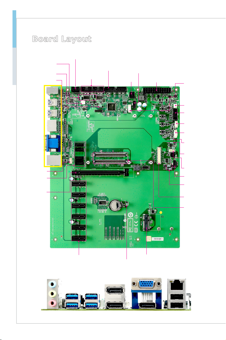
Board Layout..............................................................................................1-4
2. Hardware Setup ...........................................................................2-1
Power Supply.............................................................................................2-3
Rear Panel I/O ...........................................................................................2-4
Connector...................................................................................................2-6
Jumper .....................................................................................................2-18
Slot...........................................................................................................2-20
3. BIOS Setup...................................................................................3-1
Entering Setup ...........................................................................................3-2
The Menu Bar ............................................................................................3-4
Main ...........................................................................................................3-5
Advanced ...................................................................................................3-6
Boot..........................................................................................................3-13
Security ....................................................................................................3-14
Chipset.....................................................................................................3-19
Power .......................................................................................................3-21
Save & Exit...............................................................................................3-23
Appendix WDT & GPIO ................................................................... A-1
WDT Sample Code ................................................................................... A-2
GPIO Sample Code .................................................................................. A-3

1-1-1
Thank you for choosing the MS-9988, an excellent COM (computer-on-
module) Express Carrier Board. It is a highly advanced, feature-rich car-
rier that offers PCIe and Mini-PCIe expansion. This carrier board also
features USB 3.0/USB 2.0 ports, a VGA port, DisplayPorts, LVDS inter-
face, a parallel port connector, serial port connectors, audio jacks, SATA
ports, etc.
1Overview

1-2
Overview COM Express Carrier Board
Specications
Storage
2 SATA 6Gb/s ports
2 SATA 3Gb/s ports
■
■
Audio
Realtek ALC887 audio codec
3 rear audio jacks
1 front audio connector
■
■
■
Graphics
VGA, DisplayPort, LVDS interfaces■
Rear Panel I/O
3 audio jacks
4 USB 3.0 ports
3 DisplayPorts
1 VGA port
1 Gigabit LAN jack
2 USB 2.0 ports
■
■
■
■
■
■
Onboard Pin Headers/ Connectors/ Jumpers
1 * 24-pin power connector
1 * 4-pin power connector
2 * system fan connectors
2 * SATA 6Gb/s ports
2 * SATA 3Gb/s ports
1 * front panel connector
1 * front audio connector
1 * parallel port connector
2 * RS-232 serial port connectors
2 * GPIO pin headers
2 * SMBus connectors
1 * USB 2.0 connector (1 port)
1 * LVDS connector
1 * keyboard/mouse connector
1 * inverter power connector
2 * BIOS select jumpers
1 * inverter power jumper
1 * LVDS power jumper
1 * AT/ATX select jumper
2 * COM port power jumpers
1 * clear CMOS jumper
■
■
■
■
■
■
■
■
■
■
■
■
■
■
■
■
■
■
■
■
■

Overview COM Express Carrier Board
1-3
Overview COM Express Carrier Board
Expansion Slots
1 PCIe x16 slot
6 PCIe x1 slots
1 Mini-PCIe slot
■
■
■
Form Factor
ATX form factor: 12” x 9.6”■
Compliance
PICMG COM Express R2.0, Type 6■
Environmental
Operating Temperature: 0oC ~ 60oC
Storage Temperature: -20oC ~ 80oC
Humidity: 5% ~ 90% RH, Non-Condensing
■
■
■

1-4
Overview COM Express Carrier Board
Board Layout
Front Audio
Connector
Mini-PCIe Slot
Clear CMOS
Jumper
AT/ATX Jumper
COM Port
Connector
USB 2.0
Connector
SATA
Port
GPIO Pin
Header
Parallel Port
Connector
Back Panel
System Fan
Connector
Keyboard/
Mouse
Connector
COM Port
Power Jumper
Power
Connector
SMBus
Connector
Front Panel
Connector
PCIe Slot
COM
Express
Connector
Inverter
Power
Connector
Inverter
Power
Jumper
LVDS
Power
Jumper
SMBus
Connector
BIOS
Select
Jumper
LVDS
Connector
GPIO Pin
Header
System Fan
Connector
PCIe Slot
Power
Connector
USB 3.0
Port
Line-In
Mic-In USB 2.0
Port
DisplayPort
Line-Out
USB 3.0
Port
LAN
Port
VGA Port
DisplayPort

2-2-1
This chapter provides you with the information about hardware setup
procedures. While doing the installation, be careful in holding the com-
ponents and follow the installation procedures. For some components, if
you install in the wrong orientation, the components will not work prop-
erly.
Use a grounded wrist strap before handling computer components. Static
electricity may damage the components.
2Hardware Setup

2-2
Hardware Setup COM Express Carrier Board
Components Reference Guide
Power Supply....................................................................................2-3
System Power Connector: PWRCONN1 ...................................................2-3
CPU Power Connector: JPWR1.................................................................2-3
Rear Panel I/O ...................................................................................2-4
Connector..........................................................................................2-6
Fan Power Connector: JSYSFAN1, JSYSFAN2 ........................................2-6
I2C Bus Connector: JSMB1, JI2C2............................................................2-6
GPIO Pin Header: JGPIO1, JGPIO2..........................................................2-7
Serial ATA Connector: SATA1 ~ SATA4 .....................................................2-7
Keyboard/Mouse Connector: JKBMS1 ......................................................2-8
Front Panel Connector: JFP1.....................................................................2-8
USB 2.0 Connector: JUSB1.......................................................................2-9
Serial Port Connector: JCOM1, JCOM2 ....................................................2-9
LVDS Inverter Connector: JINVDD1 ........................................................2-10
LVDS Connector: JLVDS1 .......................................................................2-10
Front Audio Connector: JAUD1................................................................ 2-11
Parallel Port Connector: JLPT1................................................................ 2-11
TPM Module Connector: JDP1 ................................................................2-12
COM Express Connectors .......................................................................2-13
Jumper.............................................................................................2-18
Clear CMOS Jumper: JCMOS1 ...............................................................2-18
AT/ATX Select Jumper: JAT_ATX1 ..........................................................2-18
COM Port Power Jumper: VCOM1, VCOM2 ...........................................2-19
BIOS Select Jumper: JBIOS1, JBIOS2....................................................2-19
LVDS Power Jumper: JVDD1 ..................................................................2-19
Inverter Power Jumper: JINV1.................................................................2-19
Slot...................................................................................................2-20
PCIe (Peripheral Component Interconnect Express) Slot........................2-20
Mini-PCIe (Peripheral Component Interconnect Express) Slot................2-20

Hardware Setup COM Express Carrier Board
2-3
Hardware Setup COM Express Carrier Board
Power Supply
System Power Connector: PWRCONN1
This connector allows you to connect a power supply. To connect to the power
supply, make sure the plug of the power supply is inserted in the proper orienta-
tion and the pins are aligned. Then push down the power supply firmly into the
connector.
13.+3.3V
1.+3.3V
14.-12V
2.+3.3V
15.Ground
3.Ground
16.PS-ON#
4.+5V17.Ground
5.Ground
18.Ground
6.+5V
19.Ground
7.Ground
22.+5V
10.+12V
20.-5V
8.PWR OK
23.+5V
11.+12V
21.+5V
9.5VSB
24.Ground
12.+3.3V
CPU Power Connector: JPWR1
This connector is used to provide power to the CPU.
4.+12V
2.Ground
3.+12V
1.Ground
Important
Make sure that all power connectors are connected to the power supply to ensure
stable operation of the motherboard.

2-4
Hardware Setup COM Express Carrier Board
Rear Panel I/O
USB 3.0
Port
Line-In
Mic-In USB 2.0
Port
DisplayPort
Line-Out
USB 3.0
Port
LAN
Port
VGA Port
DisplayPort
Audio Ports
These audio connectors are used for audio devices. It is easy to differentiate
between audio effects according to the color of audio jacks.
Line-In (Blue) - Line In, is used for external CD player, tapeplayer or other
audio devices.
Line-Out (Green) - Line Out, is a connector for speakers or headphones.
Mic (Pink) - Mic, is a connector for microphones.
USB 3.0 Port
The USB 3.0 port is backward-compatible with USB 2.0 devices and supports
data transfer rate up to 5 Gbit/s (SuperSpeed).
DisplayPort
DisplayPort is a digital display interface standard. This connector is used to con-
nect a monitor with DisplayPort inputs.
VGA Port
The DB15-pin female connector is provided for monitor.
■
■
■

Hardware Setup COM Express Carrier Board
2-5
Hardware Setup COM Express Carrier Board
LAN Port
The standard RJ-45 LAN jack is for connection to the Local Area Network (LAN).
You can connect a network cable to it.
Yellow Green/ Orange
LED Color LED State Condition
Left Yellow Off LAN link is not established.
On (steady state) LAN link is established.
On (blinking) The computer is communicating with another
computer on the LAN.
Right Green Off 10 Mbit/sec data rate is selected.
On 100 Mbit/sec data rate is selected.
Orange On 1000 Mbit/sec data rate is selected.
USB 2.0 Port
The USB (Universal Serial Bus) port is for attaching USB devices such as key-
board, mouse, or other USB-compatible devices.

2-6
Hardware Setup COM Express Carrier Board
Connector
Fan Power Connector: JSYSFAN1, JSYSFAN2
The fan power connectors support system cooling fan with +12V. When con-
necting the wire to the connectors, always note that the red wire is the positive
and should be connected to the +12V; the black wire is Ground and should be
connected to GND.
I2C Bus Connector: JSMB1, JI2C2
This connector, known as I2C, is for users to connect System Management Bus
(SMBus) interface.

Hardware Setup COM Express Carrier Board
2-7
Hardware Setup COM Express Carrier Board
GPIO Pin Header: JGPIO1, JGPIO2
This connector is provided for the General-Purpose Input/Output (GPIO) periph-
eral module.
Serial ATA Connector: SATA1 ~ SATA4
This connector is a high-speed Serial ATA interface port. Each connector can
connect to one Serial ATA device.
Important
Please do not fold the SATA cable into a 90-degree angle. Otherwise, data loss
may occur during transmission.

2-8
Hardware Setup COM Express Carrier Board
Keyboard/Mouse Connector: JKBMS1
This connector is provided to connect a keyboard and a mouse.
Front Panel Connector: JFP1
This front panel connector is provided for electrical connection to the front panel
switches & LEDs and is compliant with Intel Front Panel I/O Connectivity Design
Guide.

Hardware Setup COM Express Carrier Board
2-9
Hardware Setup COM Express Carrier Board
USB 2.0 Connector: JUSB1
This connector, compliant with Intel I/O Connectivity Design Guide, is ideal for con-
necting high-speed USB interface peripherals such as USB HDD, digital cameras,
MP3 players, printers, modems and the like.
Important
Note that the pins of VCC and GND must be connected correctly to avoid possible
damage.
Serial Port Connector: JCOM1, JCOM2
This connector is a 16550A high speed communications port that sends/receives 16
bytes FIFOs. You can attach a serial device to it.
PIN SIGNAL DESCRIPTION
1
2
3
4
5
6
7
8
9
DCD
RXD
TXD
DTR
GND
DSR
RTS
CTS
VCC_COM
Data Carrier Detect
Receive Data
Transmit Data
Data Terminal Ready
Signal Ground
Data Set Ready
Request To Send
Clear To Send
12V or 5V power output,
selected by jumper

2-10
Hardware Setup COM Express Carrier Board
LVDS Inverter Connector: JINVDD1
The connector is provided for LCD backlight options.
LVDS Connector: JLVDS1
The LVDS (Low Voltage Differential Signal) connector provides a digital interface
typically used with flat panels. After connecting an LVDS interface flat panel to
the JLVDS1, be sure to check the panel datasheet and set the LVDS jumper to
proper power voltage.
39.LVDSB_CLK#
27.LVDSB_DATA#1
25.LVDSB_DATA1
23.GND
21.LVDSA_DATA#3
19.LVDSA_DATA3
17.GND
15.LVDSA_DATA#1
13.LVDSA_DATA1
11.LVDS_BLON
9.L_BKLT_CTRL#
7.LVDS_DDC_CLK
5.LCD_VDD
3.LCD_VDD
1.+12V
40.
LVDSA_CLK#
28.LVDSB_DATA#0
26.
LVDSB_DATA0
24.GND
22.LVDSA_DATA#2
20.LVDSA_DATA2
18.GND
16.LVDSA_DATA#0
14.LVDSA_DATA0
12.LVDS_DETECT#_C
10.LVDS_VDD_EN
8.LVDS_DDC_DATA
6.LCD_VDD
4.+12V
2.+12V
37.LVDSB_CLK
35.GND
33.LVDSB_DATA#3
31.LVDSB_DATA3
29.GND
38.LVDSA_CLK
36.GND
34.LVDSB_DATA#2
32.LVDSB_DATA2
30.GND
Important
Pin 12 is a detect pin. When using a customized LVDS cable, pin 12 should be a
signal ground with a low impedance. Otherwise, LVDS will not function.
Table of contents