SBC81205 Series Quick Installation Guide
©Copyright 2009 AXIOMTEK Co., Ltd.
Version A2 Dec 2009
Printed in Taiwan
94181205020E
2
III. Connectors
Connectors Label Connectors Label
FRONT PANEL CN1 USB 1 CONNECTOR USB1
AXIOM ACPI CN2 USB 2 CONNECTOR USB2
ATX 4 PIN 12V IN
CONNECTOR CN4 USB 3, 4 CONNECTOR USB3
LAN2 Ext. Speed LED CN5 USB 5,6 CONNECTOR USB4
LAN2 Ext. Link/ACT LED CN6 SYSTEM FAN1 CONNECTOR FAN1
LAN1 Ext. Speed LED CN8 SYSTEM FAN2 CONNECTOR FAN2
LAN1 Ext. Link/ACT LED CN7 CPU FAN CONNECTOR FAN3
RJ-45 PORT 1 LAN1 COM1 PORT COM1
RJ-45 PORT 2 LAN2 COM2 PORT COM2
LGA775 SOCKET CPU1 MOUSE CONNECTOR MS1
S-ATA PORT 1 SATA1 KEYBOARD CONNECTOR KB1
S-ATA PORT 2 SATA2 VAG PORT VGA1
S-ATA PORT 3 SATA3 PARALLEL PORT PRN1
S-ATA PORT 4 SATA4 FLOPPY PORT FDD1
Intel®HD Audio Digital
Header HDA1
-- End of Connectors Table --
Please refer to the SBC81205 Series Product Information CD for complete User’s Manual, drivers and utilities.
SBC81205 Series Quick Installation Guide
©Copyright 2009 AXIOMTEK Co., Ltd.
Version A2 Dec 2009
Printed in Taiwan
94181205020E
3
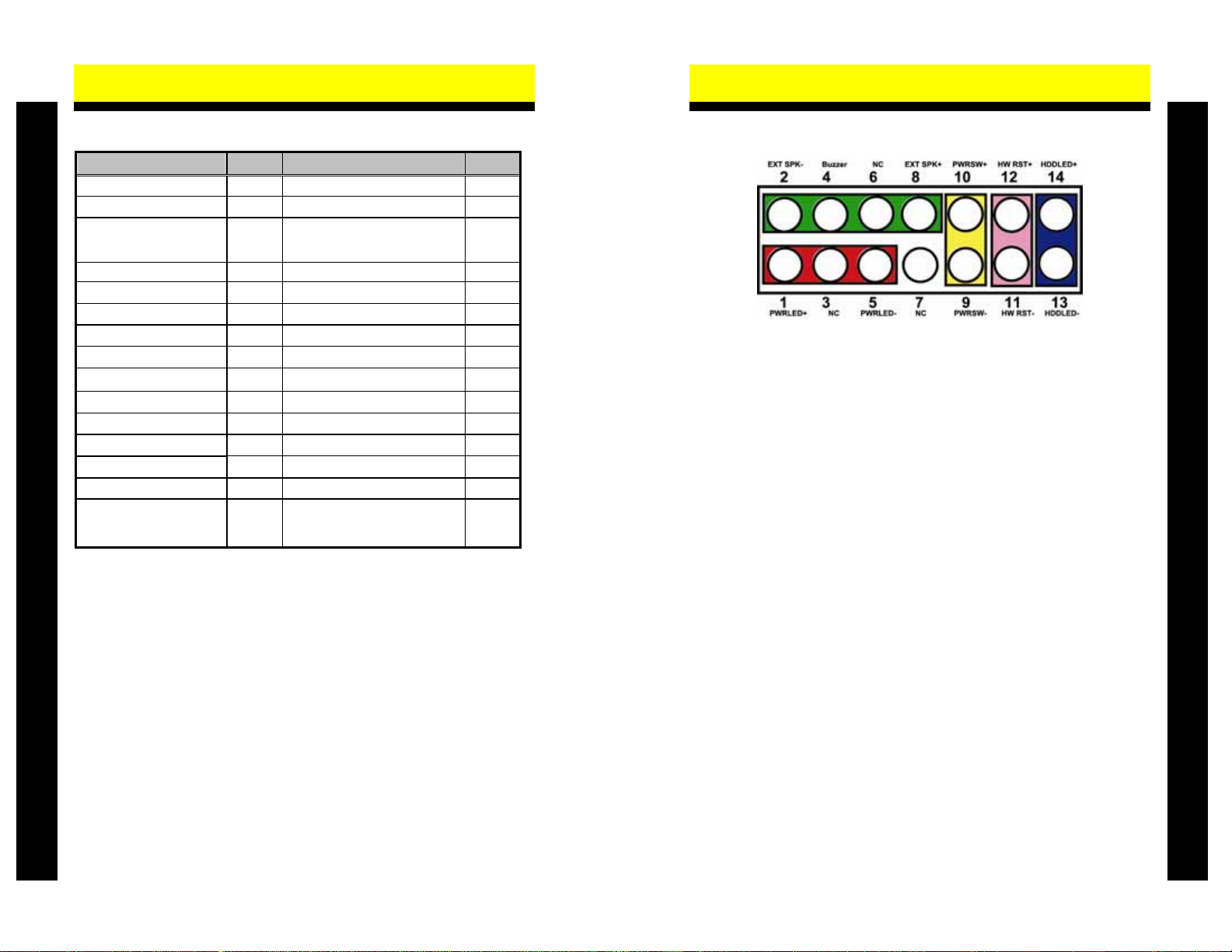
IV. Front Panel Connectors (CN1)
Power LED
Pins 1, 3, 5 connect the system power LED indicator to its respective switch on
the case. Pin 1 is +, and pin 5 assigned to -. Pin 3 is defined as NC.
External Speaker and Internal Buzzer Connector
Pins 2, 4, 6, 8 can be connected to the case-mounted speaker unit or internal
buzzer.
Power Button
Pins 9 and 10 connect the front panel’s ATX power button to the card.
Hardware Reset
Pins 11 and 12 are designed for Hardware Reset.
HDD Activity LED
This connector extends to the hard drive activity LED on the control panel. This
LED will flash when the HDD is being accessed. Pins 13 and 14 can be
connected to the hard disk drive and front panel HDD LED.
Please refer to the SBC81205 Series Product Information CD for complete User’s Manual, drivers and utilities.


