AXIOMTEK DASP-52032 User manual

DASP-52032
16 Isolated D/I and &
16 Relay Output Card
User’s Manual

ii
Disclaimers
The information in this manual has been carefully checked and is
believed to be accurate. Axiomtek Co., Ltd. assumes no responsibility
for any infringements of patents or other rights of third parties which
may result from its use.
Axiomtek assumes no responsibility for any inaccuracies that may be
contained in this document. Axiomtek makes no commitment to
update or to keep current the information contained in this manual.
Axiomtek reserves the right to make improvements to this document
and/or product at any time and without notice.
No part of this document may be reproduced, stored in a retrieval
system, or transmitted, in any form or by any means, electronic,
mechanical, photocopying, recording, or otherwise, without the prior
written permission of Axiomtek Co., Ltd.
Copyright 2004 by Axiomtek Co., Ltd.
All rights reserved.
September 2004, Version A1.0
Printed in Taiwan

iii
ESD Precautions
Integrated circuits on computer boards are sensitive to static
electricity. To avoid damaging chips from electrostatic discharge,
observe the following precautions:
Do not remove boards or integrated circuits from their anti-static
packaging until you are ready to install them.
Before handling a board or integrated circuit, touch an unpainted
portion of the system unit chassis for a few seconds. This helps to
discharge any static electricity on your body.
Wear a wrist-grounding strap, available from most electronic
component stores, when handling boards and components.
Trademarks Acknowledgments
AXIOMTEK is a trademark of Axiomtek Co., Ltd.
IBM is a registered trademark of International Business
Machines Corporation.
MS-DOS, and Windows 95/98/NT/2000 are trademarks of
Microsoft Corporation.
Phoenix-Award is a trademark of Phoenix-Award Software,
Inc.
IBM, PC/AT, PS/2, VGA are trademarks of International
Business Machines Corporation.
Intel and Celeron, Pentium III are trademarks of Intel
Corporation.
Other brand names and trademarks are the properties and
registered brands of their respective owners.
iv
Table of Contents
Chapter 1 Introduction.....................................................1
1.1 Features ...................................................................2
1.2 Specifications..........................................................2
1.3 Accessories.............................................................4
Chapter 2 Hardware Installation ...................................5
2.1 Board Layout...........................................................5
2.2 Signal Connections.................................................6
2.2.1 Signal Connection Descriptions ..............................6
2.3 Jumper Setting ......................................................11
2.4 DI/DO Circuits and Wiring ....................................13
2.4.1 SPDT Relay: Single Pole Double Throw................. 13
2.4.2 Isolated Input: AC/DC Polarity-Free..................... 13
2.5 Quick Setup and Test ...........................................14
Chapter 3 Registry Structure and Format...................19
3.1 Overview ................................................................19
3.2 Relay Output..........................................................19
3.3 Isolated Input.........................................................20
Appendix A Dimension of DASP-52032 and
Accessories ..........................................................................21

DASP-52032 Card User’s Manual
Introduction 1
C h a p t e r 1
Introduction
The DASP-52032 is a PCI-bus, 16 isolated D/I and 16 relay output
card. It supports not only optical isolation (2500VDC), but also
over-voltage protection (50VDC) to enhance the reliability of the
system. The DASP-52032 also supports two types of relay actuator-
SPDT & SPST, making it suitable for controls and sensing
applications such as load switching, external switching detection, and
contact closure.
Easy to Troubleshoot Hardware Resource- PCI Scan
Utility
The PCI scan utility can scan all the DASP products within the system,
and can show users all system resources, such as serial numbers,
IRQ, and I/O addresses. This lets users clearly see through and
immediately know whether all DASPs are working normally,
decreasing the time of searching confirmation.

DASP-52032 Card User’s Manual
Introduction
2
1.1 Features
16 optically isolated digital input channels
8 SPDT & 8 SPST relay output channels
On board relay status LED indicator
AC/DC polarity-free isolated input
Output status read-back
Optical isolation on input channels (2500VDC) and
high
Over-voltage protection (50VDC)
Serial number on EEPROM supported
Windows® 98/NT/2000/XP and Labview 6.0/7.0
driver supported
Complete sample program- VB, VC, BCB, Delphi
1.2 Specifications
Isolated Digital Inputs
Channels: 16
Optical isolated: 2500VDC
Photo-coupler: PC-3H4
Photo-isolator response time: 20μs
Over-voltage protect: 50VDC
Input voltage:
VIH (max.) 36VDC
VIH (min.) 4VDC
VIL (max.) 3VDC
Low Logic 0-3VDC
High Logic 4-36VDC

DASP-52032 Card User’s Manual
Introduction 3
Input current:
10 VDC 2.9mA (typical)
12 VDC 3.6mA (typical)
24 VDC 7.5mA (typical)
36 VDC 11.5mA (typical)
Relay Outputs
Output channels: 16
Relay type: 8 SPDT & 8 SPST
Rating (resistive): 10 A @120 VAC, 6 A @ 250 VAC,
5 A @ 30 VDC
Relay on/off time: 10ms typical
Max. switching power: 62.5VA ,60W
Max. switching voltage: 250VAC,220VDC
Breakdown voltage: 750 Vrms (1 sec)
Operate time: 5ms
Release time: 4ms
Life expectancy: 10,000,000 operations
General Environment
I/O connector: 2 sets 37-pin D-Sub type female
Power consumption:
+5 V @ 250 mA (typical)
+5 V @ 800 mA (max.)
Operation temperature: 0 ~ 60°C
Storage temperature: -20 ~ 70°C
Humidity: 0 to 90% non-condensing
Dimensions: 185mm x 122mm

DASP-52032 Card User’s Manual
Introduction
4
1.3 Accessories
To make the DASP-52032 functionality complete, we carry a
versatility of accessories for different user requirements in the
following items:
Wiring Cable
CB-89037-2:
37-pin male D-sub type cable with 2m length
CB-89037-5:
37-pin male D-sub type cable with 5m length
The shielded D-sub cable with 2m and 5m are designed
for the DASP-52032 connector, respectively.
Terminal Block
TB-88037:
D-sub 37P female terminal block with DIN-rail mounting
The terminal block is directly connected to I/O connector
CON1 and CON2 of the DASP-52032.

DASP-52032 Card User’s Manual
Hardware Installation 5
C h a p t e r 2
Hardware Installation
2.1 Board Layout
Board Layout for DASP-52032

DASP-52032 Card User’s Manual
Hardware Installation
6
2.2 Signal Connections
2.2.1 Signal Connection Descriptions
Signal Connections for DASP-52032
CON1:
The I/O connector CON1 on the DASP-52032 is a 37-pin
D-sub female connector for digital input signals. CON1
enables you to connect to accessories, the terminal block
TB-88037, with the shielded D-sub cable CB-89037-2 or
CB-89037-5.
CON2:
The I/O connector 40-pin header box connector CON2 on
the DASP-52032 is transformed into a 37-pin D-sub
female connector for digital input signals. CON2 enables
you to connect to accessories, the terminal block
TB-88037, with the shielded D-sub cable CB-89037-2 or
CB-89037-5.

DASP-52032 Card User’s Manual
Hardware Installation 7
Digital Input Connector CON1 and CON2
CON1/2
CB-89037
TB-88037
DIO Signal Connections for DASP-52032

DASP-52032 Card User’s Manual
Hardware Installation
8
The pin assignment of CON1 of DASP-52032 is listed as follows.
D-Sub 37-pin Connector for DASP-52032 CON1
Pin Description Pin Description
37 DIL_7 19 DIH_7
36 DIL_6 18 DIH_6
35 DIL_5 17 DIH_5
34 DIL_4 16 DIH_4
33 DIL_3 15 DIH_3
32 DIL_2 14 DIH_2
31 DIL_1 13 DIH_1
30 DIL_0 12 DIH_0
29 GND 11 COM_7
28 COM_6 10 NO_7
27 NO_6 9 NC_2
26 COM_5 8 COM_2
25 NO_5 7 NO_2
24 COM_4 6 NC_1
23 NO_4 5 COM_1
22 NC_3 4 NO_1
21 COM_3 3 NC_0
20 NO_3 2 COM_0
1 NO_0

DASP-52032 Card User’s Manual
Hardware Installation 9
NO n: normal open of the channel n
GND: ground
COM n: common of the channel n
DI nH: digital input signal (+) of the channel n
NC n: normal close of channel n
DI nL: digital input signal (-) of the channel n
D-Sub 37-pin Connector for DASP-52032 CON2
2 4 6 8 10 12 14 16 18 20 22 24 26 28 30 32 34 36 38 40
1 3 5 7 9 11 13 15 17 19 21 23 25 27 29 31 33 35 37 39

DASP-52032 Card User’s Manual
Hardware Installation
10
Pin Description Pin Description
37 DIL_15 19 DIH_15
36 DIL_14 18 DIH_14
35 DIL_13 17 DIH_13
34 DIL_12 16 DIH_12
33 DIL_11 15 DIH_11
32 DIL_10 14 DIH_10
31 DIL_9 13 DIH_9
30 DIL_8 12 DIH_8
29 GND 11 COM_15
28 COM_14 10 NO_15
27 NO_14 9 NC_10
26 COM_13 8 COM_10
25 NO_13 7 NO_10
24 COM_12 6 NC_9
23 NO_12 5 COM_9
22 NC_11 4 NO_9
21 COM_11 3 NC_8
20 NO_11 2 COM_8
1 NO_8

DASP-52032 Card User’s Manual
Hardware Installation 11
2.3 Jumper Setting
Each digital input channel of DASP-52032 can be configured to AC
type or DC type independently. Jumper 1 ~ Jumper 8 relates DI0~DI7,
and Jumper 9 ~ Jumper 16 relates DI8~DI15, as listed in the following
table. When the AC input type of a specific channel is configured, the
input path of the channel is automatically attached to an AC filter with
a time constant of 1.2ms (60Hz low pass).
Jumper 0~7 and Jumper 8~15 of DASP-52032
Jumper Channel Jumper Channel
JP1 DI_0 JP9 DI_8
JP2 DI_1 JP10 DI_9
JP3 DI_2 JP11 DI_10
JP4 DI_3 JP12 DI_11
JP5 DI_4 JP13 DI_12
JP6 DI_5 JP14 DI_13
JP7 DI_6 JP15 DI_14
JP8 DI_7 JP16 DI_15

DASP-52032 Card User’s Manual
Hardware Installation
12
132
132
Jumper DC signal input AC signal input with filter
JPn 1-2 3-4

DASP-52032 Card User’s Manual
Hardware Installation 13
2.4 DI/DO Circuits and Wiring
2.4.1 SPDT Relay: Single Pole Double Throw
The contact rating of the relay output is 120V AC/10A, 250V AC/6A,
and 30V DC/5A. The basic layout and wiring is presented as below.
Block Diagram of Internal Circuits and Wiring of SPDT Relay
Digital Output for DASP-52032
2.4.2 Isolated Input: AC/DC Polarity-Free
The normal input voltage range is AC/DC 4-32V (AC 50-500 Hz). The
basic layout is presented as below.
Block Diagram of Internal Circuits and Wiring of Isolated Digital
Input for DASP-52032

DASP-52032 Card User’s Manual
Hardware Installation
14
2.5 Quick Setup and Test
To install a new DASP-52032 into an IBM PC compatible computer, at
first, power-off the PC and open its chassis, then plug the
DASP-52032 into a PCI slot of mother-board. The DASP-52032 is a
plug and play device for MS Windows, and the OS will detect your
DASP-52032 after you power on the PC. The detail of driver and
software installation is described in software manual of DASP-52032.
After the hardware and software installation, user can emulate and
test DASP-52032 step by step as follows.
To perform a complete test of DASP-52032, we can
route the input signals of DASP-52032 with a
specific input pattern for read-back. And the output
status of each channel can be observed directly
from the on-board led indicator of each channel, or
to estimate the mechanical movement of the SPDT
relay of each channel. And then, by following the
DASP-52032 test branch of the ToolWorkShop
which will fully test all the digital I/O channels of
the DASP-52032 as descried in the following
paragraphs.
Launch the ‘PCI Configuration Utility’ of
DASP-52032 to ensure that the resource of
DASP-52032 is properly dispatched by the OS.
Press the scan button in the toolbar of the ‘PCI
Configuration Utility’ to find the installed
DASP-52032, and then check the resource list.

DASP-52032 Card User’s Manual
Hardware Installation 15
Scan DASP-52032 with PCI Configuration Utility and Check the
Dispatched Resource

DASP-52032 Card User’s Manual
Hardware Installation
16
Exit the ‘PCI Configuration Utility’ and launch the
‘ToolWorkShop’ for DASP-52032.
Launch ToolWorkShop
Select board test
Table of contents
Other AXIOMTEK PCI Card manuals

AXIOMTEK
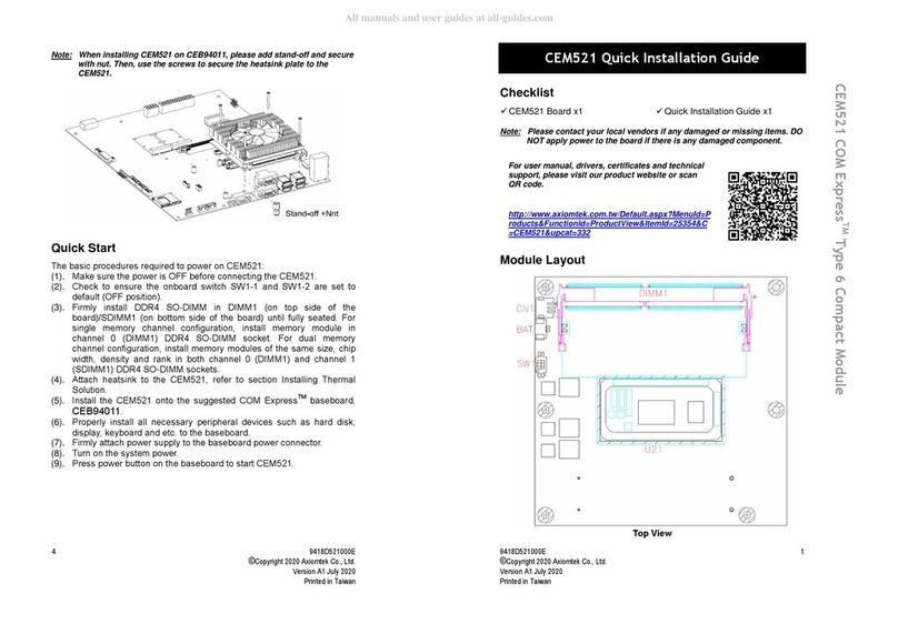
AXIOMTEK CEM521 User manual

AXIOMTEK
AXIOMTEK AX93501 User manual

AXIOMTEK
AXIOMTEK AX92325 User manual

AXIOMTEK
AXIOMTEK AC5426P User manual

AXIOMTEK
AXIOMTEK AX5420P User manual

AXIOMTEK
AXIOMTEK DASP-52016 User manual

AXIOMTEK
AXIOMTEK SCB184 User manual

AXIOMTEK
AXIOMTEK SCM187 User manual

AXIOMTEK
AXIOMTEK AX92321-4U User manual