manuals.online logo
Brands
  1. Home
  2. •
  3. Brands
  4. •
  5. Axminster
  6. •
  7. Industrial Equipment
  8. •
  9. Axminster SX4-DIGI User manual

Axminster SX4-DIGI User manual

SX4-DIGI
Tilt Head Mill Drill
AXMINSTER
Engineer
SERIES
Code 505108
Original Instructions
AT: 04/05/2021
BOOK VERSION: 2
Cert No: SX4
Axminster Tool Centre Ltd
Axminster Devon
EX13 5PH UK
axminstertools.com
Type Mill Drill
Model SX4-DIGI conforms to the machinery example for which the
EC Type-Examination Certificate No TA 385162509
has been issued by Shanghai SIEG Machinery Co., Ltd
at: No.555 CaoFeng Rd., South to No. 17 Bridge of Caoan Rd., SHANGHAI CHINA
and complies with the relevant essential health and safety requirements.
2006/42/EC
2014/30/EU
EN 61000-6-2: 2005
EN 61000-6-4: 2007/A1: 2001
declares that the machinery described:-
This machine complies with the following directives:
EU Declaration of Conformity
Signed
Andrew Parkhouse
Operations Director Date: 17/08/2016
1
IMPORTANT SAFETY INSTRUCTION
READ ALL INSTRUCTIONS AND WARNINGS BEFORE USING THE MACHINE
Operator, please remember
1.When using electric tools, machines or equipment, basic safety precautions
should always be followed to reduce the risk of fire, electric shock,
and personal injury.
2.Keep work area clean. Cluttered areas invite injuries.
3.Consider work area conditions. Don’t expose equipment for rain or wet place.
Don’t store flammable liquid around the machine, like petrol and etc.
4.Keep children away, all children should be kept away from the work area.
5.In order to protect personal safety, all the equipment should have safe
grounding device.
6.Stay alert. Never operate the machine when you are tired.
7.Do not operate the mill if you have excessively drinking or use narcotic,
the alcohol and drugs can influence people’s judgment.
8.Do not wear loose clothing or jewelry as they can be caught in moving parts,
it is very dangerous.
9.Wear restrictive hair covering to contain long hair.
10.Use eye and ear protection when you are working.
11.Keep proper position and balance when you are working.
2
Content
(1)Specifications …………………………………………………………… 3
(2)The features and parts drawing for the Machine ………………… 5
(3)Machine set up …………………………………………………………… 6
(4) Transmission system …………………………………………………… 7
(5) Operation and maintenance …………………………………………… 8
(6)Trouble shooting ……………………………………………………… 14
PS:
Parts list ( I ) ……………………………………………………………… 16
Parts list (II ) ……………………………………………………………… 17
Parts list (Ⅲ ) …… ……………………………………………………… 18
3
SX4 milling and drilling machine used infinitely variable speed transmission,
speed display and angle display, have the advantage of fashion feature,
moving stably, easy to operation and etc. The machine used popularly, have
the comprehensive function of drilling, milling, screwing and threading. It
is an ideal machine for home to make model, study metalworking and repair
machine.
(1)Specifications
1.Max. Drilling capacity 30mm
2.Max. Milling capacity 40mm
3.Face mill capacity 55mm
4.Max. Spindle stroke 85 mm
5.Distance from spindle axis to column surface 290 mm
6.Distance from spindle axis to worktable 415 mm
7.Morse taper of spindle nose MT4
8.Spindle speed 100-1600 r/m ±10%
9.Table effective size 820×240 mm
10.T-slot size 14 mm
11.Table cross travel 250 mm
12.Tale longitudinal travel 450 mm
13.Motor output power 1500 W
14.Weight (Net/Gross) 355 / 390 KG
4
Packing list
No. Name Description QTY
1 Milling and drilling
machine
SX4 1
2 Drill chuck set(fixed on
the machine)
B18 1
3 Double end wrench 8*10,14*17,19*22 1 per item
4 L Hex. Wrench 4、5、6、12 1 per item
5 Oil can 1
6 Slated carve 1
7 Taper shank 1
8 Speed handle 1
9 Draw bar 1
10 T-nut 2
11 Bottom foot adjustable
screw
4
12 GB6172-86 M12 hexagon thin nut 4
13 Safety wire 1A 2
14 Introduction SX4 1
5
(2) The features and parts drawing for the Machine
1 Base plate 12 Speed display
2 Cross feed hand wheel 13 Z axis Motor
3 Hand wheel for locking 14 Column
4 Worktable 15 Small handle for locking
5 Angle display 16 Connecting plate
6 Micro speed change handle 17 The nut for locking
7 Spindle sleeve lock
handle
18 On/off switch
8 Depth display 19 The handle with button
9 Spindle box 20 The wire
10 Emergency stop 21 Small change handle for locking
11 Control plate 22 Longitudinal feed hand wheel
6
(3)Machine set up
Choose the right place for bed,
The bed and worktable fixed by four nuts. When you fix the bed please consider
the following things: the machine should working for a long time and keep
acute, the machine should fixed in right position so that it can be working
good.
Considering the right environment,
1)Fix flat adjustable plate for the worktable
2)Don’t expose the bed in the sun, that influence the acute of bed
3)Do not place the bed in wet or damp environment, the steel can be rust in
that environment
Important measures for fix
1)Drill four fix hole on the bed surface(Attention:Choose the good position
to make sure the longitudinal handle (Y) can easily moving and operate)
2)Put the bed on hazard ground , fix the worktable and bed together by four
M10 nut
Before you start the machine, you should know well about the features, function
and how to operate. Before you open it, please check the machine condition,
like the wire, voltage and power supplies according to the mechanical switch
and speed button.
1. Please fasten the entire gripping holder before fix the machine tool.
2. Please check the power and voltage proper or not.
7
3. Please refuel machinery oils to the surface of the machine.
4. Please check the chuck, the chuck lock and stationary pin, and let them
in zero load condition.
5. Please make sure the transmission is well, the operation handle is in
right position, the tools like drilling bit and milling cutter are all
stable and fastened. Loose the main spindle box and lock the handle.
6. When the bed is working, the spindle is clockwise rotation.
7. When the bed is working, all the wiring should have safety ground device
to keep safety.
8. Please take care of the condition of the machine when you operate it,
if there are any abnormal sign, stop the machine at once and repair it.
(4) Transmission system
The transmission of the machine contained spindle timing belt pulley, spindle
bearing and motor timing belt pulley. When the brushless dc motor start, the
motor and the spindle timing belt pulley drive the spindle rotation, and then
the machine worked. Spindle speed can be changed freely at the speed range.
The spindle speed is 100-1600 r/m, and you can see the present speed on the
spindle LCD screen.
9
button to “TAPPING”),push the button on the spindle handle , the machine
can tapping in direct-adverse direction, and on the LCD screen there will
be “FORWARD”or “REVERSE”to show the present condition.
6、When you want to use the small feed function, firstly you tight the handle
on the right, the 3 operate handle with button was locked ,and then switch
the small feed handle on the right can real the small speed adjustment.
7、Push the button “ UP” or “DOWN” to control the spindle (Z) move high
or low . “UP” is up quickly, and “DOWN” is down quickly. The machine
cannot use this function when the machine is milling. The cutter is adjust
before milling, you can adjust the cutter to right place according to the
height you want to cutting, and then lock the spindle handle and make the
machine working .
8、Horizontal milling can be realized by spindle rotation. First ,loose the
fix parts on the left land; Secondly, rotation the spindle and let go your
hand, .When you rotate it to left, there will be a limit angle to prevent
the angle more than 450. When you rotate it to right it can realize the
function of horizontal milling, you can see the angle number on the LCD,
rotate it to the angle you need and then lock the 3 nuts.
9、Push “EMERGENCY STOP” , and the machine will be stopped. In urgently moment,
push the “EMERGENCY STOP”button , the machine can stop at once ,and then
you can deal with the question. When the question settled, you can start the
machine again.
10
OPERATE THE MACHINE
1、The machine must stopped when you fix the cutter or other tool.
2、Clean the inner of the spindle (MT4)and cutter, put the cutter into the
spindle nose, put in the stem and lock it.
3、You should clamp all the parts you want to process and then adjust to the
right position.
4、Loose the lock handle of column, swing the up-down handle to lower the
spindle.
5、Start the machine, adjust the speed, swing the multipurpose handle, and
then the machine can start to mill.
6、When you milling the work piece, please lock the spindle and headstock.
In order to prevent size change during the work, please lock the
longitudinal and lateral gag.
7、When you change the drill chuck or mill chuck, loose the protective cover
and put it aside, then relative the screw, use the hammer to remove the
taper-shank from spindle, and then loose the stamp to change the drill chuck
or mill chuck.
After use the machine, please cut off the power, clean the bed and fill some
oil on the surface of the bed to prevent been rusted to keep beautiful and
function.
Gag adjustment
13
display toα1 with level, when you push “Calibrate”,the display showed
“0”。And change the degree to the next angle α2,the screen will show
the angle number (α2+α1),and then push the button for 3 second ,the number
will be changed to the number α2.
3.Angle display stay a degree α with level, the number will be showed on the
screen accordingly, when you push “HOLD”,αthe number is locked,and the
pointer on both side sparkling, and the button released when you push the
button again .
4.When the angle display is in a degree αless than 450,push “0%”,it display
the number of tgα;If the angle display is in a degree α more than 450,
push “0%”, it display the number of tg(900-α).
5. The field of the angle measured is 0-900, if you don't push any function
key in 3 second the angle display will stopped.
6. When the electric symbol appears on a monitor to indicate that the battery
has been run down, and the angle display stop to work. Please open the battery
cover behind and change the battery of CR2032 3V.If you do not use the machine
for a long time, please take the battery out to prevent leakage or damage
the instruments.
14
(6)TROUBLE SHOOTING
Please don't do any repair if the motor is working or the power not cut off.
SYMPTOM POSSIBLE CAUSE CORRECTIVE ACTION
Motor will not
start
1.No power
2.Low voltage
3.Open circuit in motor or loose
connections
1.Pull out the red emergency stop
switch button, close the chuck
safety cover
2.Check power supply for proper
voltage
3.Inspect all lead connections on
motor for loose or open connections
Fuses or circuit
breakers trip open
1. Short circuit in line cord or
plug
2.Short circuit in circuit board
3.Incorrect fuses or circuit
breakers in power supply
1. Inspect cord or plug for damaged
insulation and shorted wires and
replace extension cord.
2.Inspect all connections on motor for
loose or shorted terminal or wom
insulation and repair
3.Install correct fuses or circuit
breakers
Motor overheats 1. Motor overloaded
2. Air circulation through the
motor restricted
1. Reduce load on motor
2. Clean out motor to provide normal
air circulation
Cross feed or
manual feed hand
wheel has sloppy
operation
1. Gibbs are out of adjustment
2. Hand wheel is loose
3. Lead screw mechanism wom or
out of adjustment
1. Tighten gig screw slimly, and
lubricate bed ways
2. Tighten hand wheel fasteners
3. Tighten any loose fasteners on lead
screw mechanism
Cross feed or
manual feed hand
wheel is hard to
move
1.Gigs are rusted
2.Gigs are too tight
3.Bed are too dry
1.Remove gigs clean shaving form bed
and dovetails ,lubricate and
readjust gigs
2.Loosen the screw and fill some oil
3.Fill some oil for bed and hand wheeel
Loud repetitious
noise coming from
machine
1.Gears is broken down in
headstock or no backlash
2.The motor is broken down
1.Change the gear
2.Change the motor
Machine stopped
during operation
1.Excessive depth of cut
2.RPM or feed rate wrong for d
cutting operation
3.Drill cutter broken down
4.The motor broken down
1.Decrease depth of cut
2.Refer to RPM feed rate chart for
appropriate rates
3.Change the drill cutter
4.Change the motor
15
Bed surface finish 1.Wrong RPM or feed rate
2.Drilling cutter broken down or
wrong selection
1.Adjust for appropriate RPM and feed
rate
2.Change the cutter
The drill is hard
to move on the
slide
1.The slide is too try
2. The gig of Z is too tight
3.There are some scrap on the
slide
1.Fill some oil
2.Adjust screw
3.Clean the slide
The spindle can't
clamp the end mill
1.Choose the wrong end mill
2.The spindle is broken
1.Change the end mill
2.Check the spindle and change the
right spindle
T nuts cannot be
fixed
1.The T nuts is broken or wrong
2.The T nuts on the worktable
is broken
1.Change the T nuts
2.Change a worktable or use a good T
nuts
16
Parts list ( I )
13
57
84
49 50
112
111
81
14
42
37
73
76
77
88
55
214
87
70
69
55
56
41
39
37
2
35
36
38
40
113
109
108
107
104
106
105
104
103
102
55
101
99
79
98
2
79
82
15
100
16
20
17
18
19
71
72 75
78
76
75
49
74
215
59
58
68
67
8
66
65
64
54
5352
62
61
83
63
85
86
60
43
51
51
48
47
46
45
44
80
12
11
10
9
8
7
6
5
4
3
2
1
76
89
90
91
92
93
94 95 96 97
126
127
126
125
121
124 123122
121120
119
118
115
117
116
115
114
110
34
33
32
31
30
28
29
28
27
27
26
24
25
24
23
22
21
121 88
129
128
17
Parts list ( II )
49173
172
130
130
131
164
49
143
49
145
152
132
130
147
142
141
140
139
136
138 98
144
137
136
135
135
106
134
176
169
176
179
168
174
175
174
6
170
165 166 8
169
167
163
133
146
55
151
150
130 130
149 161
160
152
153
154
155
155
162
154
156
158
157
43
159
148
178
177
177
180
181
182
183
184
171 130
185
130
130
186
18
Parts list ( Ⅲ )
232
235
211
234
229
228
212
213
196
197 2198199200218209
208
233
219
224
205
206
230
217
216
222
221
220
226
221
152
227
152
220
221
226
221
222
231
217
216
223
174
207
209
208
174
211
210
206
205
204
203
200
199
198
2
197
196
142
141
140
201
202
182183190 191 2
174
192
169
193 177
193
177
176
169
177
166
165
194
6
177
176
169
195
225
2
187
169
187
188
189
174

Other Axminster Industrial Equipment manuals

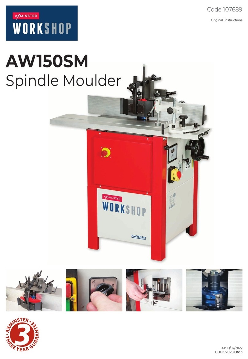
Axminster AW150SM User manual

Axminster

Axminster AW150SM User manual

Axminster NV 750s User manual

Axminster

Axminster NV 750s User manual

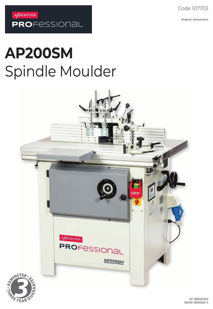
Axminster PROFESSIONAL AP200SM User manual

Axminster

Axminster PROFESSIONAL AP200SM User manual

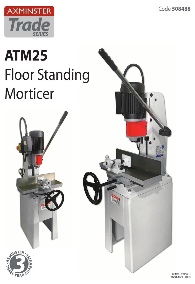
Axminster Trade Series User manual

Axminster

Axminster Trade Series User manual

Axminster WORKSHOP AW118CI User manual

Axminster

Axminster WORKSHOP AW118CI User manual

Axminster Trade Series User manual

Axminster

Axminster Trade Series User manual

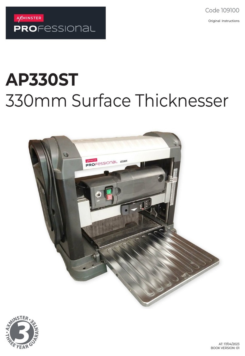
Axminster PROfessional AP330ST User manual

Axminster

Axminster PROfessional AP330ST User manual

Popular Industrial Equipment manuals by other brands

Nilfisk cfm VHW310 instruction manual

Nilfisk cfm

Nilfisk cfm VHW310 instruction manual

Wise RS Series manual

Wise

Wise RS Series manual

swepac PVEL-D USER MANUAL IN ORIGINAL

swepac

swepac PVEL-D USER MANUAL IN ORIGINAL

Nordson Smart Gun Customer product manual

Nordson

Nordson Smart Gun Customer product manual

GAPOSA P200 Series Reference manual

GAPOSA

GAPOSA P200 Series Reference manual

GE HS15-66a-9G-CUL Important safety instructions

GE

GE HS15-66a-9G-CUL Important safety instructions

Siemens SIMATIC RF662A operating instructions

Siemens

Siemens SIMATIC RF662A operating instructions

JUKI AW-3S instruction manual

JUKI

JUKI AW-3S instruction manual

GUIDANCE MARINE Artemis Mk6 FAT Initial setup

GUIDANCE MARINE

GUIDANCE MARINE Artemis Mk6 FAT Initial setup

SMC Networks ZXP7 01 X1 Series Operation manual

SMC Networks

SMC Networks ZXP7 01 X1 Series Operation manual

3M 3M-Matic 800rf Instructions and parts list

3M

3M 3M-Matic 800rf Instructions and parts list

Toptech MultiLoad III installation guide

Toptech

Toptech MultiLoad III installation guide

AB Regin Corrigo E manual

AB Regin

AB Regin Corrigo E manual

ABB HT842291 Operation manual

ABB

ABB HT842291 Operation manual

Balluff BIC 1I22-P2A02-M18MN2-EPX07-050 installation guide

Balluff

Balluff BIC 1I22-P2A02-M18MN2-EPX07-050 installation guide

SCHUNK FDB Assembly and operating manual

SCHUNK

SCHUNK FDB Assembly and operating manual

Acoustic Signature TA-2000 instruction manual

Acoustic Signature

Acoustic Signature TA-2000 instruction manual

REMS Unimat 75 operating instructions

REMS

REMS Unimat 75 operating instructions

manuals.online logo
manuals.online logoBrands
  • About & Mission
  • Contact us
  • Privacy Policy
  • Terms and Conditions

Copyright 2025 Manuals.Online. All Rights Reserved.