General Safety Instructions for 230V Machines
5
• Clean machines by wiping with a damp soapy cloth. Do not
use solvents or cleaners that may damage plastic parts or
painted/coated surfaces. Keep water and solvents away from
all electrical components, leads and plugs.
• When storing or leaving tools for any length of time, spray
bare metal surfaces with a protective spray to minimise surface
corrosion.
• Always isolate machines and power tools from the power
supply when not in use or when changing parts, cutters and
blades or when making any adjustments.
• Before using any machine or power tool, ensure that all
locking-nuts, chucks etc, are tightened and secure. Check that
all loose keys, spanners and other tools have been removed.
• Always ensure that long hair is tied back or retained by a band,
hat or safety helmet. Remove all loose jewellery to prevent it
from catching in rotating parts of the machine.
• Always check that the correct machining or cutting speed has
been selected.
• Do not operate machinery or power tools when tired or under
the influence of alcohol, drugs or certain medicines.
• WHEN USING MACHINES ALWAYS WEAR SUITABLE EYE
PROTECTION, EAR DEFENDERS AND DUST OR FUME
INHALATION PROTECTION.
• WARNING!! KEEP TOOLS AND EQUIPMENT OUT OF THE
REACH OF CHILDREN, UNLESS THEY ARE UNDER SUPERVI-
SION.
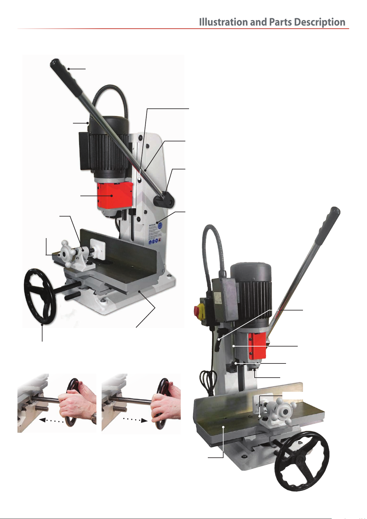
Specific Safety Instruction for Morticers
• Ensure that the morticer is firmly fixed to its base as the force
exerted through the operating handle could be enough to over
balance the machine.
• Ensure that the operating handle is returned to the
upright position after cutting a mortice.
• Mortice chisels have very sharp ends, handle them with
great care.
• Make sure that the timber is held firmly down against the
table, either with the vice or the hold down clamps.This
prevents the possibility of the timber being pulled upwards
as the mortice chisel is withdrawn from the hole.
Code 508488
Model ATM25
Rating Trade
Power 0.75kW 230V, 1ph
Chisel Stroke 125mm
Max Height of Timber with 12.7mm Chisel and Bit 225mm
Max Chisel Size Softwood 25mm
Max Chisel Size Hardwood 19mm
Overall L x W x H 660x 515 x 1,538mm
Weight 160kg